Indian motorcycle 2017. Service Manual - page 15
4.28
9927618 R03 - 2017 Indian Motorcycle (Full-Size) Service Manual
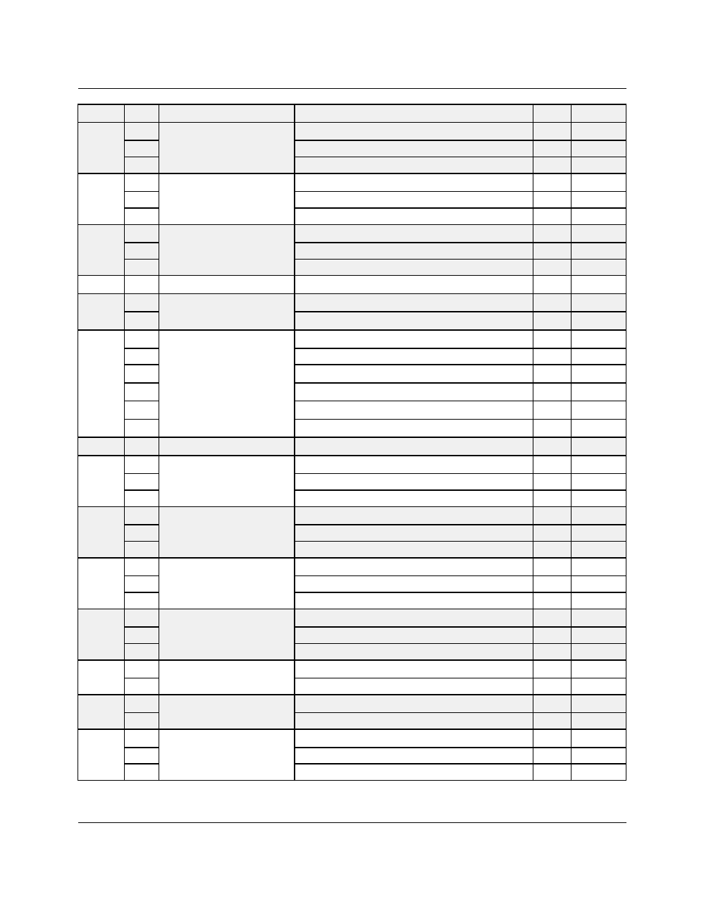
SPN
FMI
COMPONENT
CONDITION
MIL
P-CODE
651
5
Injector 1
Driver Circuit Open/Grounded
ON
P0261
3
Driver Circuit Short to B+
ON
P0262
4
Driver Circuit Grounded
ON
P1262
652
5
Injector 2
Driver Circuit Open/Grounded
ON
P0264
3
Driver Circuit Short to B+
ON
P0265
4
Driver Circuit Grounded
ON
P1265
677
5
Starter Solenoid Driver Circuit
Driver Circuit Open/Grounded
ON
P0615
3
Driver Circuit Short to B+
ON
P0617
4
Driver Circuit Grounded
ON
P0616
731
4
Knock Sensor 1
Voltage Too Low
ON
P0327
904
5
Wheel Speed Sensor (Front)
Open / Short
ON
C1030
2
Input Abnormal / Signal Failure
ON
C1031
907
2
Wheel Speed Sensor (Rear)
Plausibility Fault
ON
C103D
3
Short to B+
ON
C113D
4
Open/Short to GND
ON
C123D
5
Open/Short
ON
C1036
8
Abnormal Frequency
ON
C133D
14
Incorrect Sensor / Improper Mounting
ON
C143D
1023
5
Trip Sudden Decelerations
Open / Short
ON
C1045
1071
5
Fan Relay Driver
Driver Circuit Open/Grounded
ON
P1481
3
Driver Circuit Short to B+
ON
P1482
4
Driver Circuit Grounded
ON
P1483
1268
5
Ignition Coil Primary Driver 1
Driver Circuit Open/Grounded
ON
P1351
3
Driver Circuit Short to B+
ON
P1353
4
Driver Circuit Grounded
ON
P1361
1269
5
Ignition Coil Primary Driver 2
Driver Circuit Open/Grounded
ON
P1352
3
Driver Circuit Short to B+
ON
P1354
4
Driver Circuit Grounded
ON
P1362
1347
5
Fuel Pump Driver Circuit
Driver Circuit Open/Grounded
ON
P0230
3
Driver Circuit Short to B+
ON
P0232
4
Driver Circuit Grounded
ON
P0231
2348
5
High Beam Lamp
Open Circuit / Short to B+
ON
C107E
6
Grounded Circuit
ON
C107F
2350
5
Low Beam Lamp
Open Circuit / Short to B+
ON
C107B
6
Grounded Circuit
ON
C107C
2367
5
Left Turn Indicator Driver
Circuit
Driver Circuit Open/Grounded
OFF
P1714
3
Driver Circuit Short to B+
OFF
P1715
4
Driver Circuit Grounded
OFF
P1716