Indian motorcycle 2017. Service Manual - page 13
3.89
WARNING
Heat sink edges are extremely sharp and could
cause personal injury. Wear gloves while removing
from the cylinder head assembly.
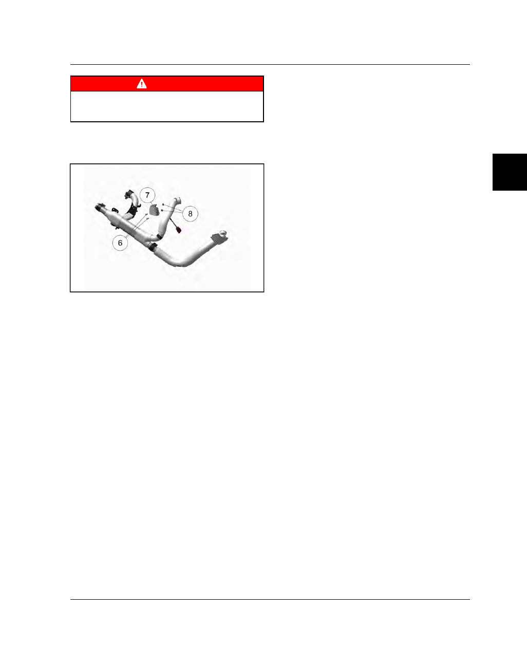
Remove the two fasteners
y
and the heat sink trim
cover
u
to access the head pipe flange nuts
i
.
Remove flange nuts.
8.
Slide the rear head pipe and cross over pipe
assembly back to remove from the front head
pipe.
9.
Remove the cross over pipe from the rear head
pipe.