Indian motorcycle 2017. Service Manual - page 14
4.12
9927618 R03 - 2017 Indian Motorcycle (Full-Size) Service Manual
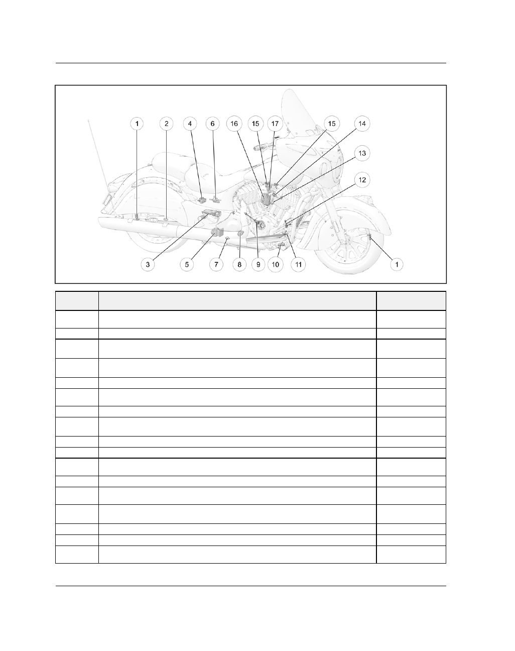
SSEENNSSOORRSS —
— PPOOW
WEERRTTRRAAIINN M
MAANNAAGGEEM
MEENNTT
NUMBER
SENSOR / LOCATION
TORQUE (IF
APPLICABLE)
q
TPMS (Tire Pressure Monitoring System) — Sensor located 180° from valve
stem
44 in-lbs (5 Nm)
w
Wheel Speed Sensor, Rear — Located at the rear caliper carrier
96 in-lbs (11 Nm)
e
ECM (Engine Control Module) — Located inside the lower RH side cover,
behind the drive sprocket
—
r
Fuse Box — Located inside the LH upper side cover. NOTE: High current J-Case
Fuse Box located behind battery box
—
t
ABS (Anti-Lock Brake) Module — Located in front of the rear tire
—
y
Canister Purge Valve (CA models only) — Located inside the RH upper side
cover
—
u
Oil Pressure Switch — Located at the rear of the LH engine case
88 in-lbs (10 Nm)
i
Gear Position Switch — Located inside the drive sprocket cover, below the
drive sprocket
43 in-lbs (5 Nm)
o
Oxygen Sensor, Rear — Located on the rear head pipe
14 ft-lbs (19 Nm)
a
Side Stand Switch — Located behind the side stand hinge
43 in-lbs (5 Nm)
s
CPS (Crank Position Sensor) — Located on the front of the engine by the oil
filter
89 in-lbs (10 Nm)
d
Oxygen Sensor, Front — Located on the front head pipe
14 ft-lbs (19 Nm)
f
Detonation “Knock” Sensor — Located on the rear face of the front cylinder
heat sink
15 ft-lbs (20 Nm)
g
CHT (Cylinder Head Temperature) Sensor — Located on the rear face of the
front cylinder head
71 in-lbs (8 Nm)
h
Fuel Injectors — Located at the cylinder head intake ports
—
j
Ignition coil — Located behind the horn assembly on the RH side of the engine
84 in-lbs (10 Nm)
k
TMAP — (Temperature / Manifold Absolute Pressure) Sensor — Located on the
back side of the intake manifold
62 in-lbs (7 Nm)