Indian motorcycle 2017. Service Manual - page 12


  Главная      Manuals     Indian motorcycle 2017. Service Manual


Search            copyright infringement  


Content      ..     10      11      12      13     ..


Indian motorcycle 2017. Service Manual - page 12


3

3.73

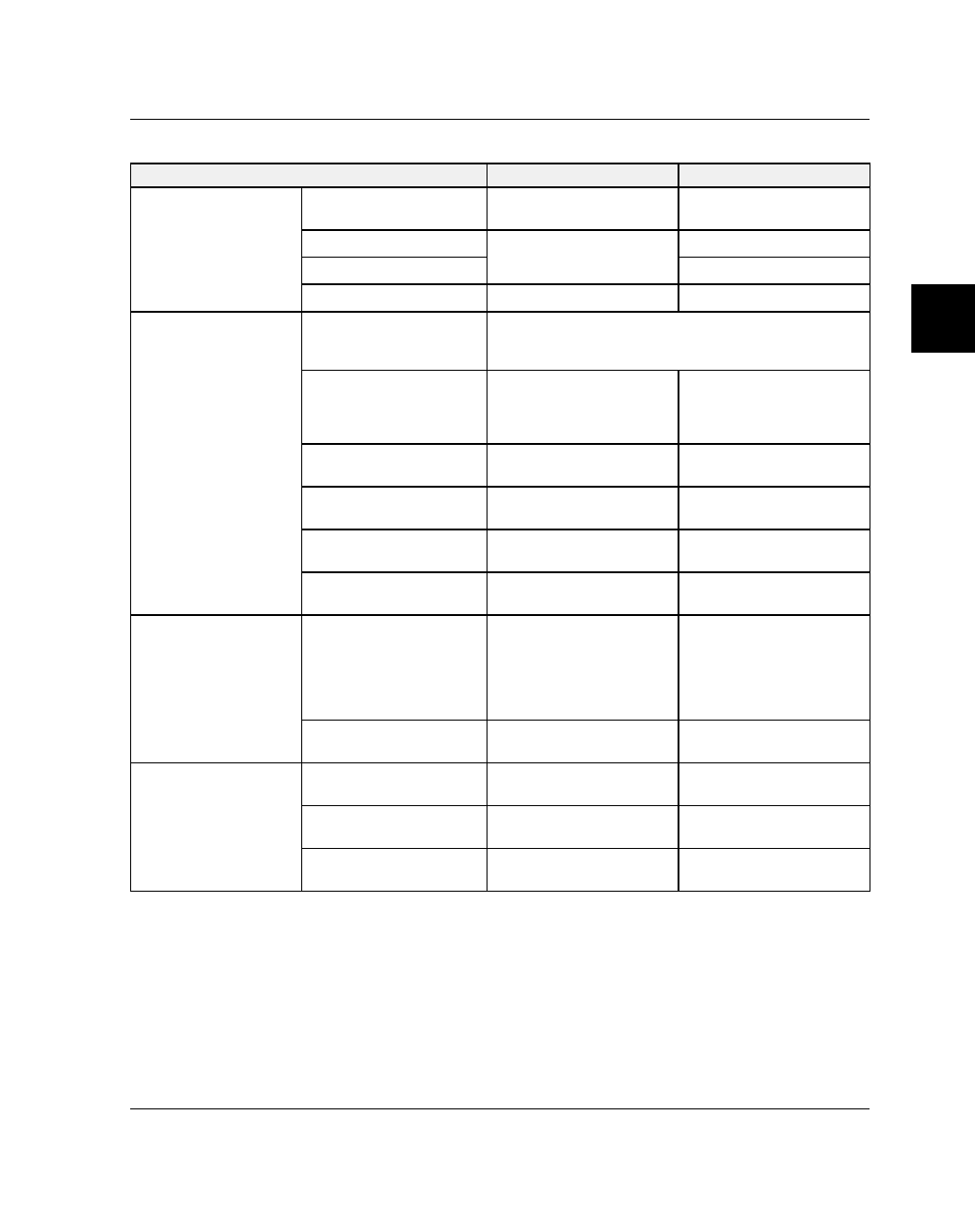
SSEERRVVIICCEE SSPPEECCIIFFIICCAATTIIOONNSS

ITEM

STANDARD

SERVICE LIMIT

Cylinder

I.D.

100.987 - 101.013
(3.9759" - 3.9769”)

Check taper and
out-of-round

Out of Round

Measure 66mm up from
base gasket surface

0.05 mm (.002")

Taper

0.05 mm (.002")

Gasket Surface Warpage

-

.1mm max. (.0039")

Piston

Piston Mark Direction

Piston orientation is determined by arrow on piston
crown.
Position BOTH pistons so arrows point to front of engine.

Piston O.D. (Nominal)
(Measured 12 mm up
from bottom of skirt, 90
degrees to pin)

100.966 - 101.004mm
(3.975 - 3.976")

Replace if piston-to-
cylinder clearance is
excessive with good
cylinder

Piston Pin Hole I.D.

22.006 - 22.012 mm
(.8664 - .8666")

22.047 mm
(.8680")

Piston Pin O.D.

21.995 - 22.000 mm
(.8659 - .8661")

21.96 mm
(.864")

Piston to Cylinder

.023 - .067 mm
(.0009 - .0026")

.15 mm
(.006")

Piston to Piston Pin

.006 - .017 mm
(.0002 - .0007")

.035 mm
(.0014")

Piston Ring Clearances

Ring End Gap - Top

(Installed)

Ring End Gap - 2nd
(Installed)Ring End Gap -
3rd (Oil Control Rails)
(Installed)

.15 - .40 mm
(.006 - .016")
.33 - .53 mm
(.013 - .021")
.15 - .35 mm
(.006 - .014")

.80 mm
(.031")
1.11 mm
(.043")
.80 mm

(.031")

Piston Ring Marks

-

“CTOP” mark must face
UP on all rings.

Piston Ring to Ring
Land

Top Ring
(1.2mm ring thickness)

.02 - .060 mm
(.0008 - .0024")

.11 mm (.0043")

2nd Ring
(1.2mm ring thickness)

.02 - .060 mm
(.0008 - .0024")

.11 mm (.0043")

Oil Control Ring

.03 - .17 mm
(.001 - .0067")

.26 mm (.010")

ENGINE / COOLING / EXHAUST

3.74

9927618 R03 - 2017 Indian Motorcycle (Full-Size) Service Manual

AASSSSEEM

MBBLLYY VVIIEEW

WSS

CCYYLLIINNDDEERR // PPIISSTTOONN

NUMBER

PART DESCRIPTION

TORQUE (IF APPLICABLE)

q

Fastener, Connecting Rod Bearing Cap

22 ft-lbs (30 Nm)

w

Bearing Cap, Connecting Rod

-

e

Bearing, Connecting Rod (52 mm)

-

r

Circlip, Wristpin

-

t

Wristpin

-

y

Piston (101 mm)

-

u

Ring, Oil Control

-

i

Ring, Compression (top 2 rings)

-

o

Gasket, Cylinder Base

-

a

Cylinder

-

s

Gasket, Cylinder Head

-

ENGINE / COOLING / EXHAUST

3

3.75

CCYYLLIINNDDEERR // PPIISSTTOONN SSEERRVVIICCEE

PPIISSTTOONN RRIINNGG PPRROOFFIILLEE AANNDD OORRIIEENNTTAATTIIOONN

NUMBER

DESCRIPTION

q

Arrows on piston crown indicating installation direction. Both arrows point toward the front of the engine.

w

Rear piston is installed closest to the primary drive side of the engine.

e

Front piston is installed closest to the camshaft side of the engine.

r

Wrist pin circlip. Install the circlip with the gap positioned at 12 o’clock.

t

Oil Control Ring

y

Compression Ring No. 2

u

Compression Ring No. 1

ENGINE / COOLING / EXHAUST

3.76

9927618 R03 - 2017 Indian Motorcycle (Full-Size) Service Manual

CCYYLLIINNDDEERR RREEM

MOOVVAALL

1.

Remove cylinder head (s). See Cylinder Head
Removal, page 3.61.

2.

Remove cylinder (s). Support pistons to prevent
damage. Place a section of hose over the cylinder
studs to prevent damage to the piston rings.

3.

Remove cylinder base gasket

q

.

4.

Clean gasket surfaces of cylinders thoroughly.

CAUTION

Careless handling of cylinder, pistons or rings may

cause irreparable damage. Do not damage gasket

surfaces during cleaning.

CCYYLLIINNDDEERR IINNSSPPEECCTTIIOONN

1.

Visually inspect cylinder bores for scratches and
wear.

2.

Inspect gasket surfaces for scratches or other
damage that may cause an oil leak.

CCYYLLIINNDDEERR BBOORREE M

MEEAASSUURREEM

MEENNTT

1.

Measure each cylinder bore in 6 places to
determine:

NOTE

Bottom measurement should be taken 2.6 in (66 mm)

up from base gasket surface.

• Cylinder Bore Inside Diameter
• Cylinder Taper
• Out of Round

2.

Use maximum measurement to determine wear.

3.

Use

the

worksheet

provided

to

record

measurements and calculate the clearance.

ENGINE / COOLING / EXHAUST

3

3.77

PPIISSTTOONN TTOO CCYYLLIINNDDEERR CCLLEEAARRAANNCCEE W

WOORRKKSSHHEEEETT

Front Cylinder

Recorded Measurement

Specification

Top “X”

Taper Service Limit: .05mm (.002")

Middle “X”

Bottom “X”

Top “Y”

Middle “Y”

Bottom “Y”

Difference between largest “Y” measurement
and smallest “Y” measurement

Taper for “Y” axis:

Difference between largest “X” measurement
and smallest “X” measurement

Taper for “X” axis:

Largest difference between any “X” axis
measurement and “Y” axis measurement

Cylinder Out-of-Round:

Out-of-Round Service Limit:
.05mm (.002")

Piston Skirt Measurement

Difference between largest “X” axis
measurement and piston measurement

Piston-to-Cylinder Clearance

*

Piston-to-Cylinder Clearance Service Limit: .15
mm (.006")

Rear Cylinder

Recorded Measurement

Specification

Top “X”

Taper Service Limit: .05mm (.002")

Middle “X”

Bottom “X”

Top “Y”

Middle “Y”

Bottom “Y”

Difference between largest “Y”
measurement and smallest “Y”
measurement

Taper for “Y” axis:

Difference between largest “X”
measurement and smallest “X”
measurement

Taper for “X” axis:

Largest difference between any “X” axis
measurement and “Y” axis measurement

Cylinder Out-of-Round:

Out-of-Round Service Limit:
.05mm (.002")

Piston Skirt Measurement

Difference between largest “X” axis
measurement and piston measurement

Piston-to-Cylinder Clearance

*

Piston-to-Cylinder Clearance Service Limit: .15
mm (.006")

Compare recorded measurement to specifications. If measured value exceeds service limit replace the
appropriate part.

NOTE

• The cylinders are Ni-SiC plated and cannot be reconditioned by boring or honing. If excessive surface

damage, taper or out-of-round exists, the cylinder must be replaced.

• If the piston-to-cylinder clearance exceeds the service limit,

measure a new piston and re-calculate the

clearance.

If the piston-to-cylinder clearance exceeds the service limits with a new piston, the cylinder must

be replaced.

ENGINE / COOLING / EXHAUST

3.78

9927618 R03 - 2017 Indian Motorcycle (Full-Size) Service Manual

CCYYLLIINNDDEERR W

WAARRPPAAGGEE M

MEEAASSUURREEM

MEENNTT

1.

Inspect cylinder for warpage at cylinder head
surface and base gasket surface.

2.

Place a straight edge diagonally across cylinder
mating surfaces in several positions. Attempt to
slide a .05mm (.002") feeler gauge under the
straight edge in each position.

3.

Replace cylinder if warped beyond the service
limit.

PPIISSTTOONN &

& PPIISSTTOONN RRIINNGG RREEM

MOOVVAALL

1.

Cover crankcase with a clean shop towel to
prevent

piston

circlip

from

falling

into

the

crankcase.

2.

Remove the left piston pin circlip

q

.

3.

Push piston pin

w

out to left side of engine and

remove the piston

e

.

4.

Rotate rings in piston grooves. Rings should rotate
freely in grooves.

5.

Clean carbon deposits from piston.

6.

Spread rings only wide enough to remove them
from piston. Spreading rings too wide will damage
them.

7.

Clean piston ring grooves. Break or cut a piston
ring in half. File or grind one edge square and
remove all burrs. Use this piston ring to carefully
clean piston ring grooves.

NOTE

A soft wire brush may be used to only clean the top

of the piston. Do not use a wire brush to clean the

sides of piston or the piston ring grooves.

ENGINE / COOLING / EXHAUST

3

3.79

PPIISSTTOONN &

& PPIISSTTOONN RRIINNGG IINNSSPPEECCTTIIOONN

1.

Visually inspect piston for cracks, excessive wear,
scoring, etc.

2.

Measure piston skirt O. D. (90° to pin and 12 mm
from bottom of piston skirt). Replace piston if worn
beyond

the

service

limit.

See

Service

Specifications, page 3.73.

3.

Calculate Piston to Cylinder Clearance. Subtract
piston O.D. from cylinder bore I.D. and compare to
specifications. See Service Specifications, page
3.73.

4.

Replace parts that do not meet specification.

NOTE

If piston-to-cylinder clearance exceeds service limit,

measure a new piston and re-calculate clearance

. If

piston-to-cylinder clearance exceeds service limits

with a new piston, cylinder must be replaced.

5.

Use a piston to push each ring squarely into
cylinder bore from bottom (push rings 25-50 mm
into cylinder).

6.

Measure installed ring end gap with a feeler
gauge and compare to specifications. See Service
Specifications, page 3.73.

7.

Install rings onto a clean piston. Push rings in until
they are flush with piston. Using a feeler gauge,
measure side clearances for the 1st & 2nd rings.

8.

Replace parts that exceed service limit.

ENGINE / COOLING / EXHAUST

3.80

9927618 R03 - 2017 Indian Motorcycle (Full-Size) Service Manual

PPIISSTTOONN PPIINN // PPIINN BBOORREE IINNSSPPEECCTTIIOONN

1.

Measure piston pin hole I. D. top to bottom (as
shown) and as close to the circlip groove as
possible with a telescoping gauge. Record the
smallest measurement.

2.

Measure piston pin O.D. at three locations. Record
largest measurement.

3.

Calculate piston pin-to-piston clearance. Subtract
pin O.D. from pin hole I.D.

4.

Measure connecting rod small end I. D. at two
locations.

5.

Calculate connecting rod-to-piston pin clearance
by subtracting pin O.D from rod hole I.D.

6.

Compare measurements to specifications and
replace

any

worn

parts.

See

Service

Specifications, page 3.73.

PPIISSTTOONN RRIINNGG IINNSSTTAALLLLAATTIIOONN

CAUTION

The rings may be damaged if they are over

expanded during installation.

1.

Lubricate all rings with engine oil.

2.

Carefully install oil control ring expander with end
gap located as shown. See Piston Ring Profile And
Orientation, page 3.75.

3.

Install top and bottom rails with end gap located
as shown. See Piston Ring Profile And Orientation,
page 3.75

4.

Install top ring (marked “C”) and second ring
(marked “CTOP”) with markings facing UP.

5.

Compress each ring by hand and rotate to be sure
they rotate freely in grooves.

6.

Locate ring end gaps as shown below in relation to
arrow on piston crown. See Piston Ring Profile And
Orientation, page 3.75.

ENGINE / COOLING / EXHAUST

3

3.81

PPIISSTTOONN IINNSSTTAALLLLAATTIIOONN

The pistons are marked with an arrow on the crown.
Install pistons on connecting rods with arrow

q

facing

the FRONT of the engine.

1.

Place a clean shop towel over crankcase to prevent
foreign material from entering crankcase.

2.

Install a new circlip on one side of the piston with
end gap facing UP (12:00 position).

IMPORTANT

Never reuse piston pin circlips.

3.

Lubricate piston pin and I. D. of connecting rod
small end with engine oil or moly lube.

4.

Install piston over connecting rod with arrow on
piston crown facing FRONT of engine.

5.

Push piston pin

w

through rod and piston pin hole

until it is stopped by circlip.

6.

Install remaining circlip

e

with end gap facing up

(12:00 position.)

7.

Make sure both piston circlips are seated properly
in the groove.

CCYYLLIINNDDEERR SSTTUUDD RREEPPLLAACCEEM

MEENNTT

1.

Use a stud extractor to remove 10 mm studs

q

.

2.

Clean threads in cases thoroughly.

3.

Apply engine oil to stud threads.

4.

Install studs and torque them to specification.

TORQUE

Cylinder Studs:

25 ft-lbs (34 Nm)

ENGINE / COOLING / EXHAUST

3.82

9927618 R03 - 2017 Indian Motorcycle (Full-Size) Service Manual

CCYYLLIINNDDEERR IINNSSTTAALLLLAATTIIOONN

NOTE

Be sure all top end parts are ready for assembly.

Sealant on crankcase parting line must not be

allowed to dry before top end is assembled and

torqued.

1.

First wash cylinders with clean solvent, then with
hot soapy water.

2.

Rinse

the

cylinders

with

clear

water

and

immediately dry with compressed air. Cylinder
bore should be wiped with a clean white shop
towel and engine oil.

3.

Apply a light coat of engine oil to piston and rings.

4.

Ensure cylinder alignment dowel pins are in place
and gasket surfaces are clean and oil-free.

5.

Apply a small amount of crankcase sealant to the
crankcase parting lines on base gasket surface as
shown.

6.

Install new cylinder base gaskets onto crankcase.

IMPORTANT

Inspect all sealing surfaces carefully for scratches or

imperfections. DO NOT allow oil or grease to contact

gaskets or sealing surfaces during the assembly

process.

7.

Apply a small amount of engine oil to inside
surfaces of a piston ring compressor band.

8.

Install piston ring compressor over rings and
compress rings into ring grooves.

CAUTION

Be sure compressor band end gap does not align

with any ring end gap when compressing the rings.

NOTE

Install cylinders in their original locations.

Cylinder

with Knock Sensor is the front cylinder.

9.

Remove protective covering from crankcase.

10. Carefully install cylinder (s) over piston/ring

assembly. Do not force cylinder over piston.
Monitor rings carefully. If a piston ring becomes
dislodged from the ring compressor; remove
cylinder, inspect ring carefully for damage.

11. Remove piston ring compressor when rings are

fully captive in cylinder.

12. Slide cylinder down over piston until seated to

base gasket and crankcase surface.

13. Repeat for other cylinder.

14. Install cylinder head (s). See Cylinder Head

Installation, page 3.67.

ENGINE / COOLING / EXHAUST

3

3.83

TTRROOUUBBLLEESSHHOOOOTTIINNGG,, CCYYLLIINNDDEERR // PPIISSTTOONN

PROBLEM

POSSIBLE CAUSE

PART(S) AFFECTED

REPAIR

RECOMMENDED

Hard Starting / Won’t Start

Low Compression

Worn Valve Guide(s)

Replace Valve Guide(s)

Poor Seating of Valve(s)

Repair or Replace

Broken Valve Spring(s)

Replace

Spark Plug Not Seated

Torque to Specification

Incorrect Valve Timing

Repair / Retest

Valve Stuck Open

Repair / Retest

Cylinder Head Gasket
Leak

Repair / Retest

Slow Starter Motor

Refer to Electrical
chapter

Worn Rings, Piston, or
Cylinder

Refer to Clutch / Primary
/ Shift chapter

Collapsed Hydraulic
Lifter(s)

Bleed Air from Lifter(s) /
Run at high idle for 10
minutes

Ignition Problem

Refer to Electrical
chapter

Fuel Problem

Refer to Engine / Cooling
/ Exhaust chapter

Electric Starter Straining
to Turn Engine Over

High Compression

Excessive carbon build-
up in combustion
chamber

De-carbon Combustion
Chamber

Excessive Starter Load

Internal Engine / Drive
Components Seized or
Binding

Determine Cause of
Seizure or Binding

Poor idle Quality (Engine
Related)

Low Compression

Collapsed Hydraulic
Lifter(s)

Bleed Air from Lifter(s) /
Run at high idle for 10
minutes

Poor Seating of Valve(s)

Repair or Replace

Excessive Oil in
Combustion Chamber

Valve Guides or worn
valve stem seals

Replace

Worn Rings, Piston, or
Cylinder

Refer to Engine / Cooling
/ Exhaust chapter

Engine Oil Overfilled

Correct Engine Oil Level

Engine Noise

Valve Train Area

Collapsed Hydraulic
Lifter(s)

Bleed Air from Lifter(s) /
Run at high idle for 10
minutes

Broken or Weak Valve
Spring(s)

Replace

Worn Camshaft or Rocker
Arm

Replace

ENGINE / COOLING / EXHAUST

3.84

9927618 R03 - 2017 Indian Motorcycle (Full-Size) Service Manual

PROBLEM

POSSIBLE CAUSE

PART(S) AFFECTED

REPAIR

RECOMMENDED

Rocker Arm Bearing
Damage

Replace

Cam Bearings Worn or
Damaged

Replace

Piston / Cylinder Area

Worn Pistons and / or
Cylinders

Replace

Worn Wrist Pin, Wrist Pin
Bore and / or Connecting
Rod

Replace

Worn Piston Rings or
Piston Ring Lands

Replace

General

Exhaust Leak

Reseal Exhaust

Timing Chain Area

Chain / Sprocket Worn

Replace

Chain Tensioner and / or
Guide Worn

Replace

Bottom End Area

Main Bearings

Refer to Transmission /
Crankshaft chapter

Rod Bearings

Refer to Transmission /
Crankshaft chapter

Loose Side Clearance

Refer to Transmission /
Crankshaft chapter

Transmission Area

Bearings

Refer to Transmission /
Crankshaft chapter

Poor High-Speed Running

Air Intake Problem

-

Refer to Fuel Delivery /
EFI chapter

Fuel Injection Problem

-

Refer to Fuel Delivery /
EFI chapter

Ignition Problem

-

Refer to Electrical
chapter

Valve Float

Weak Valve Springs

Replace

Insufficient Valve Travel

Worn Camshaft / Rocker
Arms

Replace

Valves Opening and
Closing at Wrong Time

Incorrect Valve Timing

Correct

Lack of Power in all RPM
Ranges

Low Compression

Worn Piston, Rings,
Cylinder, Poor Valve
Seating

Repair / Replace

Valve Timing Incorrect

Cam Chain and Sprockets

Correct

Damaged Cam Gears

Replace

Valve Float

Weak Valve Springs

Replace

ENGINE / COOLING / EXHAUST

3

3.85

PROBLEM

POSSIBLE CAUSE

PART(S) AFFECTED

REPAIR

RECOMMENDED

Insufficient Valve Lift

Worn Camshaft / Rocker
Arms

Replace

Ignition / Fuel Injection
System

Refer to Fuel Delivery /
EFI or Electrical chapter

Oiling Problem

Oil Overfilled

Correct Engine Oil Level

ENGINE / COOLING / EXHAUST

3.86

9927618 R03 - 2017 Indian Motorcycle (Full-Size) Service Manual

EEXXHHAAUUSSTT

AASSSSEEM

MBBLLYY VVIIEEW

WSS

EEXXHHAAUUSSTT SSYYSSTTEEM

M

NUMBER

PART DESCRIPTION

TORQUE (IF APPLICABLE)

q

Fastener, Muffler Hanger — M8 x 1.25 x 16 (QTY.4)

18 ft-lbs (24 Nm)

w

Clamp, Exhaust (QTY.4)

31 ft-lbs (42 Nm)

e

Fastener, Rear Head Pipe Hanger — M8 x 1.25 x 20
(QTY.4)

18 ft-lbs (24 Nm)

r

Clamp, Worm Drive

31 in-lbs (4 Nm)

t

Clamp, Worm Drive

31 in-lbs (4 Nm)

y

Oxygen Sensor (QTY.2)

14 ft-lbs (19 Nm)

u

Fastener, Head Pipe Trim Cover — M6 x 1.0 x 20
(QTY.4)

84 in-lbs (10 Nm)

i

Nut, Head Pipe — M8 x 1.25 (QTY.4)

15 ft-lbs (20 Nm)

ENGINE / COOLING / EXHAUST

3

3.87

EEXXHHAAUUSSTT SSEERRVVIICCEE

M

MUUFFFFLLEERR RREEM

MOOVVAALL

WARNING

Engine and exhaust components get hot and remain

hot for a period of time after the engine is stopped.

Wear insulated protective clothing or wait for

components to cool sufficiently before working on

the machine.

1.

Using a flat head screwdriver, loosen (do not
remove) the rear heat shield clamps

q

.

2.

Loosen the forward muffler clamps

w

between the

head pipe / cross over pipe and muffler.

3.

Remove the four fasteners

e

securing each

muffler to the rear hanger.

4.

Slide the muffler assemblies rearward to remove
from the head pipe and cross over pipe.

ENGINE / COOLING / EXHAUST

3.88

9927618 R03 - 2017 Indian Motorcycle (Full-Size) Service Manual

CCRROOSSSS OOVVEERR PPIIPPEE RREEM

MOOVVAALL

WARNING

Engine and exhaust components get hot and remain

hot for a period of time after the engine is stopped.

Wear insulated protective clothing or wait for

components to cool sufficiently before working on

the machine.

1.

Remove saddlebags, if equipped.

2.

Using a flat head screwdriver, loosen the heat
shield clamps on both sides of the motorcycle until
the ends can be opened up. Remove the heat
shields

q

.

3.

Remove left and right muffler assemblies, page
3.87.

4.

Remove cross over pipe support fastener

w

from

left hand side of the motorcycle.

5.

Disconnect the rear oxygen sensor connector

e

.

Connector is tucked into the RH side frame panel.

6.

Loosen rear head pipe and cross over pipe
exhaust clamps

r

and remove rear head pipe

support fasteners

t

.

7.

ENGINE / COOLING / EXHAUST


Content      ..     10      11      12      13     ..