Indian motorcycle 2017. Service Manual - page 10


  Главная      Manuals     Indian motorcycle 2017. Service Manual


Search            copyright infringement  


Content      ..     8      9      10      11     ..


Indian motorcycle 2017. Service Manual - page 10


3

3.41

CCAAM

M CCHHAAIINN SSEERRVVIICCEE

LLOOCCKKIINNGG TTHHEE CCRRAANNKKSSHHAAFFTT FFOORR SSEERRVVIICCEE

This procedure describes how to lock the crankshaft in
the

Top

Dead

Center

(TDC)

position

using

commercially available hand tools.

1.

Remove the spark plugs. See Spark Plug Removal,
page 2.23.

2.

Remove the stator. See Stator Removal, page
10.30.

3.

Using special service tool PF– 51239, rotate the
crankshaft counterclockwise (primary side) until
the front piston is at TDC. See Cylinder Head,
page 3.39.

4.

Lock the crankshaft by inserting a 5/16” pin punch
(or equivalent) into the locking hole

q

.

NOTE

It may be necessary to rotate the crankshaft slight

forward or back to properly align holes.
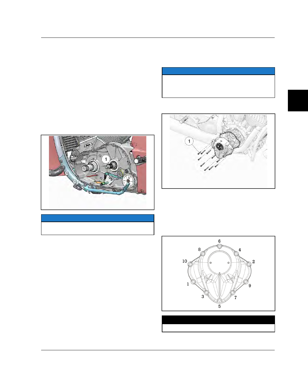
CCAAM

M CCHHAAIINN CCOOVVEERR RREEM

MOOVVAALL // IINNSSTTAALLLLAATTIIOONN

1.

Remove the RH floorboard / master cylinder
assembly and move out of the way. See Floorboard
(Driver), Removal, page 7.18

NOTE

The RH floorboard and rear brake master cylinder

can be removed as an assembly. It is not necessary to

disconnect the brake line from the master cylinder

while performing this procedure.

2.

Remove the ten fasteners

q

securing the cam

chain cover to the inner timing cover.

3.

Remove the cam chain cover and gasket.

4.

INSTALLATION is performed by reversing the
removal procedure.

5.

Clean gasket mating surfaces and install cam
chain cover using a new gasket.

6.

Torque cam chain cover fasteners following the
specified torque sequence.

TORQUE

Cam Chain Cover Fasteners:

15 ft-lbs (20 Nm)

ENGINE / COOLING / EXHAUST

3.42

9927618 R03 - 2017 Indian Motorcycle (Full-Size) Service Manual

CCAAM

M CCHHAAIINN TTEENNSSIIOONNEERR RREEM

MOOVVAALL

CAUTION

Do not rotate engine with tensioner(s) removed.

1.

Remove the cam chain cover. See Cam Chain
Cover, Removal / Installation, page 3.41.

2.

Remove cam chain tensioner fastener

q

and

remove the cam chain tensioner.

3.

Remove the external snap ring

w

from the

tensioner arm and remove arm and spring as an
assembly.

CCAAM

M CCHHAAIINN TTEENNSSIIOONNEERR IINNSSPPEECCTTIIOONN

1.

Visually inspect ratchet plunger

q

for damage,

scoring, or burrs.

2.

Lubricate ratchet plunger with engine oil. Depress
the release pawl and move plunger in and out of
housing

w

to check for smooth movement without

binding.

3.

Inspect the ratchet pawl mechanism

e

and verify

proper spring operation.

4.

Replace tensioner assembly if plunger doesn’t
fully extend when released from a compressed
state.

5.

Inspect tensioner arm for excessive wear marks
from timing chain, cracks or fatigue.

6.

Inspect the tensioner arm spring for cracks or
fatigue.

CCAAM

M CCHHAAIINN TTEENNSSIIOONNEERR IINNSSTTAALLLLAATTIIOONN

1.

Verify that the engine is at TDC and the timing
marks are properly aligned. See Cylinder Head,
page 3.39.

2.

Slide the tensioner arm and spring over the pivot
pin and, using a needle nose pliers or similar tool,
loop the tensioner arm spring over the retainer pin
and slide down until fully seated.

3.

Install the tensioner arm snap ring.

4.

Compress the tensioner assembly and slide into
position over the alignment dowel.

5.

Install

tensioner

fastener

and

torque

to

specification.

TORQUE

Tensioner Fastener:

15 ft-lbs (20 Nm)

6.

With a new gasket and both mating surfaces clean,
install the cam chain cover. See Cam Chain Cover,
Removal / Installation, page 3.41.

ENGINE / COOLING / EXHAUST

3

3.43

CCAAM

M CCHHAAIINN GGUUIIDDEE RREEM

MOOVVAALL

1.

Remove the cam chain cover. See Cam Chain
Cover, Removal / Installation, page 3.41

2.

Remove the two fasteners

q

securing the cam

chain guide to the engine and remove the guide
and spacers.

CCAAM

M CCHHAAIINN GGUUIIDDEE IINNSSTTAALLLLAATTIIOONN

1.

If removed, install the cam chain. See Cam Chain
Installation, page 3.44.

2.

Install cam chain guide

q

and fasteners

w

.

Torque to specification.

TORQUE

Cam Chain Guide:

71 in-lbs (8 Nm)

3.

Install the cam cover. See Cam Chain Cover,
Removal / Installation, page 3.41.

CCAAM

M CCHHAAIINN RREEM

MOOVVAALL

1.

Place motorcycle in an upright position with the
front wheel clamped in a wheel vise.

2.

Drain the engine oil. SeeEngine Oil / Filter
Change, page 2.9.

3.

Remove spark plugs. See Spark Plug Removal,
page 2.23.

4.

Place an oil drain pan beneath the engine to catch
any residual oil when primary and cam chain
covers are removed.

5.

Remove the cam chain cover. See Cam Chain
Cover, Removal / Installation, page 3.41.

6.

Perform the crankshaft locking procedure. See
Locking the Crankshaft for Service, page 3.41.

7.

Remove the cam chain tensioner and tensioner
arm

assemblies.

See

Cam

Chain

Tensioner

Removal, page 3.42.

8.

Remove the cam chain guide. See Cam Chain
Guide Removal, page 3.43

9.

Remove the camshaft and crankshaft sprocket
fasteners

q

.

10. Pull the camshaft sprocket, crankshaft sprocket

and cam chain off as an assembly.

11. Collect the woodruff key from the crankshaft.

ENGINE / COOLING / EXHAUST

3.44

9927618 R03 - 2017 Indian Motorcycle (Full-Size) Service Manual

CCAAM

M CCHHAAIINN IINNSSTTAALLLLAATTIIOONN

CAUTION

The Thunder Stroke 111 is an INTERFERENCE

ENGINE. If the camshafts and crankshaft must be

turned independently of each other to set valve

timing, the camshafts must be set to TDC prior to

rotating the crankshaft. Failure to do this may cause

the pistons to contact the valves resulting in engine

damage.

1.

Verify that the camshafts are set to TDC. Camshaft
timing marks

q

&

w

should be aligned as shown.

The camshaft sprocket alignment dowel

e

should

be at 12 o’clock.

2.

Perform

METHOD 1

of the crankshaft locking

procedure. This will ensure the crankshaft is
locked in the TDC position. See Locking the
Crankshaft for Service, page 3.41.

3.

Place the woodruff key in the end of the
crankshaft.

4.

Working on a flat surface, assemble the timing
chain onto the crankshaft and camshaft sprockets
as shown.

1. Align timing marks

r

.

2. Position the chain on the sprockets so that the

dark

chain

links

line

up

with

sprocket

hashmarks.

5.

Slide the chain and sprockets onto the crankshaft
and center camshaft as an assembly.

6.

Verify that the crankshaft woodruff key is still in
place and that the timing marks are still aligned.

7.

Install crankshaft and camshaft sprocket fasteners
and washers and torque to specification.

TORQUE

Camshaft / Crankshaft Sprocket Fasteners:

52 ft-lbs

(70 Nm)

8.

Install the cam chain guide. See Cam Chain Guide
Installation, page 3.43.

9.

Install the cam chain tensioner and tensioner arm
assemblies. See Cam Chain Tensioner Installation,
page 3.42.

10. Install the cam chain cover. See Cam Chain Cover,

Removal / Installation, page 3.41.

11. Remove the crankshaft

locking pin installed

during the crankshaft locking procedure in step 2.

12. Install stator.Stator Installation, page 10.31.

13. Install flywheel. See Flywheel Installation, page

5.22.

14. Install clutch assembly and clutch rack. See Clutch

Installation, page 5.19.

15. Install

torque

compensator.

See

Torque

Compensator Installation, page 5.21.

16. Install

primary

cover.

See

Primary

Cover

Installation, page 5.12.

ENGINE / COOLING / EXHAUST

3

3.45

CCAAM

MSSHHAAFFTT // LLIIFFTTEERR SSEERRVVIICCEE -- EENNGGIINNEE OOUUTT

LLIIFFTTEERR RREEM

MOOVVAALL

IMPORTANT

Keep mated parts together for assembly. It is

important to put lifters and lifter blocks back in the

same location.

1.

Remove cylinder heads and push rods from
engine. See Cylinder Head Removal, page 3.61.

2.

Remove push rod tubes

q

by pulling out of the

lifter blocks to release the o-rings.

3.

Starting with the front lifter block, remove the
three fasteners

w

and the lifter block.

4.

Using a T25 Torx, remove the fastener

e

securing

the lifter retaining plate to the inner cam chain
cover and remove plate.

5.

IMPORTANT

When removing the lifter guides, be careful not to

drop them into the inner cam chain cover.

Remove lifter guides

r

and pull lifters out of bore.

6.

Repeat steps 3–5 to remove the rear lifters.

ENGINE / COOLING / EXHAUST

3.46

9927618 R03 - 2017 Indian Motorcycle (Full-Size) Service Manual

LLIIFFTTEERR IINNSSTTAALLLLAATTIIOONN

1.

Apply a light coat of engine oil to each lifter and
slide into bore in the same position from which it
was removed.

2.

Rotate each lifter so that the flat surface

q

is

parallel with the lifter guide slot.

3.

Starting at the front cylinder, install lifter guides

w

.

4.

Install lifter retaining plate

e

with bevelled

fastener relief facing up.

5.

Install retaining plate fastener

r

and torque to

specification.

TORQUE

Lifter Retaining Plate Fastener:

62 in-lbs (7 Nm)

6.

Repeat steps 3–5 for the rear cylinder lifters.

7.

Install new gaskets into lifter blocks and install
lifter blocks and fasteners finger tight.

8.

Torque lifter block fasteners to specification.

TORQUE

Lifter Block Fasteners:

89 in-lbs (10 Nm)

9.

Install push rod tubes

t

with new o-rings

y

.

10. Install

cylinder

heads.

See

Cylinder

Head

Installation, page 3.67.

11. Install inner and outer valve cover gaskets. See

Valve Cover Installation, page 3.60.

ENGINE / COOLING / EXHAUST

3

3.47

CCAAM

MSSHHAAFFTT CCAARRRRIIEERR RREEM

MOOVVAALL

NOTE

Base and head gasket seal is released when

removing camshaft carrier. Replacement of both

head and base gasket is recommended to prevent oil

leaks. Keep mated parts together.

1.

Remove the engine from the frame and place on
an engine stand. See Removing Engine From
Frame, page 3.12.

2.

Remove lifters. See Lifter Removal, page 3.45.

3.

Remove cam chain, cam chain tensioner and
guide. See Cam Chain Removal, page 3.43.

4.

Remove the three remaining camshaft carrier
fasteners

q

.

5.

Grasp the camshaft carrier

w

and pull straight out

to remove the three camshafts, outer bearings and
carrier as an assembly.

NOTE

The camshaft ends are slip-fit to the inner bearings

and should come out by hand.

CCAAM

MSSHHAAFFTT CCAARRRRIIEERR DDIISSAASSSSEEM

MBBLLYY

IMPORTANT

Camshafts are slip-fit to carrier bearings. Once the

carrier assembly has been removed from the engine,

the intake (center) camshaft will be held in place by
gear preload only. Use caution while working on the

carrier assembly so that camshafts do not fall from

carrier and become damaged.

1.

Remove

the

camshaft

carrier

assembly.

See

Camshaft Carrier Removal, page 3.47.

2.

Remove the six fasteners and the bearing retainer
plate

q

from the carrier assembly.

3.

Place the camshaft carrier in a soft-jawed vise and
use nylon strapping or rope

w

to create an

interference between the camshaft gear teeth, thus
locking the camshafts.

4.

Loosen, do not remove, the exhaust camshaft
fasteners

e

.

5.

Remove the camshaft carrier assembly from the
vise and remove camshaft fasteners. Care should
be taken so camshafts don’t fall out of the carrier
during this process.

ENGINE / COOLING / EXHAUST

3.48

9927618 R03 - 2017 Indian Motorcycle (Full-Size) Service Manual

6.

Noting position in the carrier for reassembly,
remove the camshafts and sprockets

r

from the

carrier bearings.

7.

Camshaft carrier bearings can be removed using a
suitable press or bearing driver. Pressure must be
applied from the backside of the carrier plate and
bearings pressed through the front.

8.

NOTE

The following procedure is to INSPECT split gear

springs only. If the split gears are damaged they

MUST be replaced as an assembly as parts are not

individually serviceable.

To separate split gears, wrap a shop rag around
the teeth of the gear so springs are contained and
remove external snap-ring

t

.

9.

Separate components of gear as shown.

ENGINE / COOLING / EXHAUST

3

3.49

CCAAM

MSSHHAAFFTT IINNSSPPEECCTTIIOONN

For the following camshaft inspection procedure,
refer to the camshaft service specifications sec-
tion. See Service Specifications, page 3.33.

1.

Visually inspect camshaft journal surfaces for
scoring or signs of insufficient lubrication. Replace
camshaft if heavy scoring or damage is noted.

2.

Inspect height of each cam lobe. Exhaust cam
lobes

q

and intake cam lobes

w

.

3.

Measure O. D. of each camshaft journal. Exhaust
journals

e

and Intake journals

r

.

ENGINE / COOLING / EXHAUST

3.50

9927618 R03 - 2017 Indian Motorcycle (Full-Size) Service Manual

CCAAM

MSSHHAAFFTT CCAARRRRIIEERR AASSSSEEM

MBBLLYY

CAUTION

Wear eye protection while assembling split camshaft

gears.

IMPORTANT

The following procedure details split gear assembly

following inspection. If the split gears are damaged

they MUST be replaced as an assembly as parts are

not individually serviceable.

1.

Load springs

q

into the inner cam gear spring

pockets.

2.

Install the outer cam gear onto the inner cam gear
making sure the alignment holes

w

are positioned

as shown.

3.

Install the spring retainer

e

, Belleville washer

r

,

and the snap-ring

t

to complete split gear

assembly.

4.

If replacing camshaft carrier bearings, press or
drive new bearings into the carrier from the front
side until seated against shoulder.

5.

Install the bearing retainer plate

y

with the

countersunk fastener holes facing out.

6.

Install fasteners and torque to specification.

TORQUE

Bearing Retainer Plate Fasteners:

62 in-lbs (7 Nm)

ENGINE / COOLING / EXHAUST

3

3.51

7.

Install woodruff keys

u

and split gear assemblies

i

onto the exhaust camshafts and set aside.

8.

Install intake camshaft

o

into helical gear

a

and

slide into the center carrier bearing

s

.

Woodruff

key should be positioned at 12 o’clock.

9.

IMPORTANT

Care must be taken when installing the exhaust

camshafts into the carrier bearings to ensure they are

in the correct location. The lobe of the RH exhaust

camshaft

d

should be

closer

to the bearing carrier

than the LH exhaust camshaft lobe.

10.

NOTE

It may be necessary to use a flat fastenerdriver or

similar tool to release the preload on the split gear

teeth when engaging the helical gear.

Install the LH and RH exhaust camshafts so the
timing marks line up as shown.

ENGINE / COOLING / EXHAUST

3.52

9927618 R03 - 2017 Indian Motorcycle (Full-Size) Service Manual

11. Install exhaust camshaft fasteners

f

and washers

g

into carrier assembly so they are finger tight.

12. Place the camshaft carrier in a soft-jawed vise and

use nylon strapping or rope

h

to create an

interference between the camshaft gear teeth, thus
locking the camshafts.

13. Torque exhaust camshaft fasteners to specification.

TORQUE

Exhaust Camshaft Fasteners:

52 ft-lbs (70 Nm)

ENGINE / COOLING / EXHAUST

3

3.53

CCAAM

MSSHHAAFFTT CCAARRRRIIEERR IINNSSTTAALLLLAATTIIOONN

NOTE

Base and head gasket seal is released when

removing camshaft carrier. Replacement of both

head and base gasket is recommended to prevent oil

leaks.

1.

Lift the camshaft carrier assembly

q

into position

so that each of the camshaft ends fits into the inner
bearings.

2.

NOTE

The camshaft ends are slip-fit to the inner bearings

and should slide in by hand.

Press the camshaft carrier assembly into the inner
bearings until carrier is fully seated on the inner
cam chain cover.

3.

Install the three fasteners

w

and torque to

specification.

TORQUE

Camshaft Carrier Fasteners:

15 ft-lbs (20 Nm)

4.

Install cam chain, cam chain tensioner and guide.
See Cam Chain Installation, page 3.44.

5.

Install lifters. See Lifter Installation, page 3.46.

6.

Install engine in frame. See Engine Installation,
page 3.17.

ENGINE / COOLING / EXHAUST

3.54

9927618 R03 - 2017 Indian Motorcycle (Full-Size) Service Manual

CCAAM

MSSHHAAFFTT SSEERRVVIICCEE -- IINN BBIIKKEE

CCAAM

MSSHHAAFFTT RREEM

MOOVVAALL

IMPORTANT

Camshaft removal with the engine installed in the

frame requires Special Tool #: PF-51455.

NOTE

Secure the woodruff keys or place a shop towel

under camshaft drive gears to ensure keys don’t fall

into the engine.

1. Remove the cam chain, guide and tensioner

assemblies. See Cam Chain Cover Removal /
Installation, page 3.41.

2. Remove the exhaust camshaft fasteners

q

.

3. Remove the remaining camshaft carrier fasteners

w

.

4. Leaving the camshafts in position in the crankcase

bearing bores, remove the camshaft bearing
carrier

e

.

5. Remove the intake

r

and exhaust

t

camshaft

drive gears.

ENGINE / COOLING / EXHAUST

3

3.55

6. Loosely assemble the lower camshaft retainer plate

y

to the main plate using two fasteners

u

.

7. Install the camshaft special tool assembly onto the

camshafts and tighten fasteners

i

until they are

hand-tight.

NOTE

The lower camshaft retainer plate should be tight

enough to support the outboard camshaft bearing

journal.

8. Install special tool spacer

o

(has dowel hole) onto

the intake camshaft and spacers

a

onto the

exhaust camshafts.

9. Install camshaft gear washers and fasteners until

they are hand-tight.

10. With the flat side of the retaining pin

s

aligned

perpendicular to the rear exhaust camshaft push-
rod tube, slide the pin in hole marked “B”

d

until it

stops.

NOTE

It will be necessary to rotate the camshaft

(clockwise) with a wrench to seat the pin.

11. Rotate the camshaft using a suitable wrench while

pressing on the retaining pin until it seats.

ENGINE / COOLING / EXHAUST

3.56

9927618 R03 - 2017 Indian Motorcycle (Full-Size) Service Manual

12. Use the second etched line (marked “B”) to

determine when the shaft is fully seated in the hole
marked “B”. The lifter is now held in place by the
retaining pin.

NOTE

The crankcase has been removed in this picture to

show the correct retaining pin position.

13. Repeat

steps

10-12

for

the

forward

exhaust

camshaft.

NOTE

For the forward exhaust camshaft you will use the

hole marked “A” and the line marked “A”.

14. Slide the third retaining pin into the front cylinder

intake camshaft position (hole marked “A”) until it
stops.

NOTE

It will be necessary to rotate the camshaft

(clockwise) with a wrench to seat the pin.

15. Rotate the camshaft using a suitable wrench while

pressing on the retaining pin until it seats at the
line marked “A”.

16. Slide the fourth retaining pin into the rear cylinder

intake camshaft position (hole marked “B”) until it
stops.

NOTE

It will be necessary to rotate the camshaft

(clockwise) with a wrench to seat the pin.

17. Rotate the camshaft using a suitable wrench while

pressing on the retaining pin until it seats at the
line marked “B”.

ENGINE / COOLING / EXHAUST


Content      ..     8      9      10      11     ..