Indian motorcycle 2017. Service Manual - page 8
 

  Главная      Manuals     Indian motorcycle 2017. Service Manual


Search            copyright infringement  


Content      ..     6      7      8      9     ..


Indian motorcycle 2017. Service Manual - page 8


3

3.9

AASSSSEEM

MBBLLYY VVIIEEW

WSS

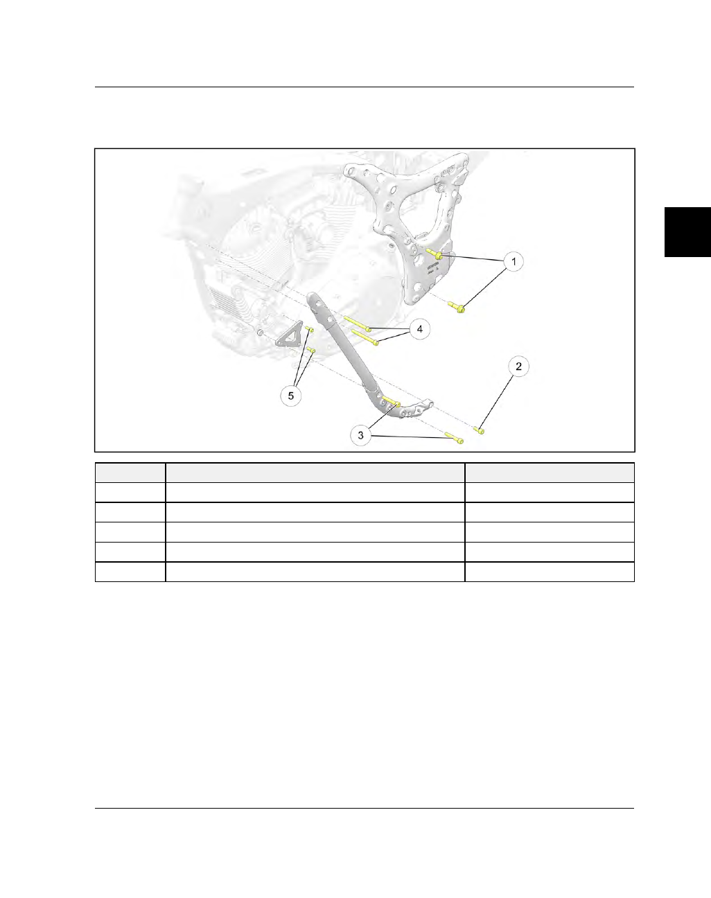
EENNGGIINNEE BBRRAACCKKEETTSS // FFAASSTTEENNEERRSS
LLEEFFTT SSIIDDEE BBRRAACCKKEETTSS // FFAASSTTEENNEERRSS

NUMBER

PART DESCRIPTION

TORQUE (IF APPLICABLE)

q

Fastener, Engine Mount — M12 x 1.75 x 50 (QTY.2)

75 ft-lbs (102 Nm)

w

Fastener, Engine Mount — M10 x 1.5 x 25 (QTY.1)

45 ft-lbs (60 Nm)

e

Fastener, Engine Mount — M10 x 1.5 x 60 (QTY.2)

45 ft-lbs (60 Nm)

r

Fastener, Frame Down Tube — M10 x 1.5 x 100 (QTY.2)

45 ft-lbs (60 Nm)

t

Fastener, Front Engine Mount — M8 x 1.25 x 20 (QTY.2)

18 ft-lbs (25 Nm)

ENGINE / COOLING / EXHAUST

3.10

9927618 R03 - 2017 Indian Motorcycle (Full-Size) Service Manual

RRIIGGHHTT SSIIDDEE BBRRAACCKKEETTSS // FFAASSTTEENNEERRSS

NUMBER

PART DESCRIPTION

TORQUE (IF APPLICABLE)

q

Fastener, Engine Mount — M12 x 1.75 x 50 (QTY.1)

75 ft-lbs (102 Nm)

w

Fastener, Engine Mount — M12 x 1.75 x 120 (QTY.1)

75 ft-lbs (102 Nm)

e

Fastener, Engine Mount — M10 x 1.5 x 60 (QTY.2)

45 ft-lbs (60 Nm)

ENGINE / COOLING / EXHAUST

3

3.11

EENNGGIINNEE RREEM

MOOVVAALL

PPRREEPPAARRAATTIIOONN FFOORR EENNGGIINNEE RREEM

MOOVVAALL

Remove the front fender with the motorcycle rest-
ing on it’s side stand, prior to placing the front tire
in a wheel vise.

NOTE

Different methods can be used to remove the

engine depending on the equipment available to

the technician. All methods require the front

wheel to be held securely in an upright position.

1.

With the motorcycle resting on it’s side stand,
remove

the

front

fender.

See

Front

Fender

Removal, page 7.26.

2.

Support

motorcycle

securely

in

an

upright

position. Clamp front tire securely in a wheel vise.

3.

Remove upper side covers. See Side Cover
(Upper), Removal / Installation, page 7.17.

4.

Remove lower side covers. See Side Cover
(Lower), Removal / Installation, page 7.17.

5.

Remove the seat. See Seat, Removal / Installation -
Classic / Vintage / Chieftain, page 7.21.

6.

Remove the battery. See Battery Removal, page
2.26.

7.

Remove the fuel tank. See Fuel Tank Removal,
page 4.15.

8.

Remove

the

complete

exhaust

system.

See

EXHAUST SERVICE.

9.

Remove the sprocket cover. See Drive Sprocket
Cover, Removal / Installation, page 8.48.

10. Remove the ignition coil assembly. See Ignition

Coil Removal / Installation, page 10.40.

11. Remove the RH and LH floorboard assemblies. See

Floorboard (Driver), Removal, page 7.18.

12. Remove highway bars, if equipped. See Highway

Bar Removal, page 7.24.

13. Loosen axle nut

q

and loosen belt tension

adjustment nuts

w

and remove belt from drive

sprocket.

14. Remove air box. See Air Box Removal, page 3.4.

15. Remove the knock sensor

e

.

16. Disconnect the TMAP sensor

r

.

17. Disconnect the CHT sensor

t

.

18. Remove both ends of the breather hose

y

from the

valve covers.

ENGINE / COOLING / EXHAUST

3.12

9927618 R03 - 2017 Indian Motorcycle (Full-Size) Service Manual

19. Disconnect electrical connectors from both fuel

injectors and feed the electrical harness and all
plugs up through the fuel rail (distribution line)
and move out of the way.

20. Using a 10 mm socket, remove the top oil cooler

fastener

u

and release the oil cooler from the

lower mounting tabs

i

.

21. Disconnect the oil pressure switch. See Sensors —

Powertrain Management, page 4.12.

22. Disconnect the gear position switch. See Sensors

— Powertrain Management, page 4.12.

23. Using a 4 mm hex wrench, remove the two

fasteners securing the sidestand switch and move
switch out of the way. See Sensors — Powertrain
Management, page 4.12.

RREEM

MOOVVIINNGG EENNGGIINNEE FFRROOM

M FFRRAAM

MEE

1.

Perform the preliminary engine removal steps
outlined in this chapter. See Preparation For
Engine Removal, page 3.11.

2.

Place a platform jack beneath the engine and raise
enough to support crankcase (Jack should just be
touching the crankcase).

3.

Using a 5 mm hex wrench, remove the fastener

q

securing the clutch cable clip to the bottom of the
LH engine case.

4.

Remove the E-clip from the end of the clutch
cable, rotate the clutch arm by hand and release
the clutch cable end from the arm.

5.

Using a 6 mm hex wrench, remove the two front
motor mount fasteners

w

from the engine case.

6.

Using an 8 mm hex wrench, remove the 4 fasteners

e r t

securing the LH front down tube to the

frame top tube and lower engine boss.

ENGINE / COOLING / EXHAUST

3

3.13

7.

Remove the LH frame down tube and side stand as
an assembly.

8.

Disconnect the stator from the regulator.

9.

NOTE

It is not necessary to clip the cable ties securing the

stator / regulator harness to the mounting bracket as

they can be moved out of the way as an assembly.

Using a 5 mm hex wrench, remove the two
fasteners

y

securing the voltage regulator to the

mounting bracket and move the regulator enough
to access the mounting bracket fasteners.

10. Remove the three regulator mounting bracket

fasteners

u

securing the regulator bracket to the

engine case and move bracket out of the way.

11. Remove the starter motor. See Starter Motor,

Removal / Installation, page 10.25.

12. Remove

CPS.

See

Sensors

Powertrain

Management, page 4.12.

13. Using a 5 mm hex wrench, remove the four

fasteners

i

securing the hard hydraulic lines to

the RH frame down tube and engine case.

ENGINE / COOLING / EXHAUST

3.14

9927618 R03 - 2017 Indian Motorcycle (Full-Size) Service Manual

14. Using an 8 mm hex wrench, remove the remaining

two fasteners

o

from the RH frame down tube and

remove.

15.

NOTE

STEPS 15–17 APPLICABLE TO CA AND

INTERNATIONAL MODELS ONLY.

Noting position, disconnect hoses

a

from the

charcoal canister.

16. Using a 5 mm hex wrench, remove the two

fasteners

s

securing the charcoal canister to the

bracket. Remove canister.

17. Remove the two fasteners

d

securing the charcoal

canister mounting bracket to the ABS bracket.

18. Disconnect the main ABS electrical connector and

two brake switch connectors from the ABS Module.

ENGINE / COOLING / EXHAUST

3

3.15

19.

NOTE

It is not necessary to remove the hydraulic lines from

the ABS module during engine removal.

Remove the four fasteners

f

from the ABS

bracket.

20. Remove the two fasteners

g

securing the starter

solenoid to the ABS bracket.

21. Move the ABS Module / bracket and hydraulic

brake lines far enough away from the RH side of
the engine so that the engine can be lowered
slightly.

22. Remove the two fasteners

h

securing the battery

tray to the engine and the grounding fastener

j

from the engine case.

23. Working from the RH side, using a 16 mm socket,

remove the two fasteners

k

securing the rear of

the motor to the frame side panel.

24. Using a pick tool, remove the two spacers

l

from

the RH side of the engine between the frame panel
and engine mounts.

ENGINE / COOLING / EXHAUST

3.16

9927618 R03 - 2017 Indian Motorcycle (Full-Size) Service Manual

25. Working from the LH side of the motorcycle,

remove the two fasteners

1 (

securing the rear of

the engine to the LH frame panel.

26. Push engine slightly to the RH side to free up from

alignment dowels. With an assistant, lower the
engine from the frame and remove from vehicle.

ENGINE / COOLING / EXHAUST

3

3.17

EENNGGIINNEE IINNSSTTAALLLLAATTIIOONN

The following procedure is written assuming the en-
gine has been assembled and is resting on an engine
stand, ready for installation.
Refer toEngine Brackets / Fasteners, page 3.9 in this
chapter for torque values and assembly views.

CAUTION

Arrange for assistance when installing engine. The

engine must be held securely to prevent damage to

engine, frame, wiring, or hoses. The engine is very

heavy and could cause severe personal injury if not

handled properly. Be sure engine is properly

supported before proceeding.

IMPORTANT

Be sure alignment dowels are in place in the LH rear

engine mounts prior to installation.

1.

Clean mating surfaces of frame and engine
crankcase. Install alignment dowels

q

.

2.

Place motorcycle in an upright position with the
front wheel clamped in a wheel vise.

3.

Position the engine on a platform jack to the left of
the motorcycle and slide into position so the
engine is orientated correctly front to back.

4.

Slide the engine back until the rear mounting ears
are aligned with the mounting holes in the frame
side panels. Adjust height of engine as needed to
align rear mounts and dowel pins.

5.

Slide the engine towards the LH frame panel until
the dowel pins are fully seated.

6.

Be sure all wiring and hoses are properly routed
before installing rear spacers and mounting
fasteners.

7.

Install the two engine mounting fasteners into the
LH frame panel and tighten until the engine is fully
drawn into the frame panel.

Do not torque

fasteners at this time.

CAUTION

Be sure engine is aligned at the proper height and

angle with the dowel pins. DO NOT force engine

alignment using the mounting fasteners, or the

dowel pins may be damaged! Adjust engine

height and angle continuously as required while

drawing up the fasteners.

ENGINE / COOLING / EXHAUST

3.18

9927618 R03 - 2017 Indian Motorcycle (Full-Size) Service Manual

8.

Working on the RH side of the engine, slide the
spacers

w

into position between the RH frame

panel and the engine crankcase.

9.

Install the two engine mounting fasteners

e

into

the RH frame panel, through the spacers and
torque to specification. See Engine Brackets /
Fasteners, page 3.9.

10. Torque the left hand rear engine mounting

fasteners to specification.

TORQUE

Rear Engine Mounting Fasteners:

75 ft-lbs (102 Nm)

11. Install the two fasteners

r

securing the battery

box to the engine and the grounding wire fastener

t

and torque to specification.

TORQUE

Battery Box Fasteners:

84 in-lbs (10 Nm)

Grounding Wire Fastener:

84 in-lbs (10 Nm)

12. Install the four fasteners

y

securing the ABS

module bracket to the rear of the engine and
torque to specification.

TORQUE

ABS Module Bracket Fasteners:

84 in-lbs (10 Nm)

13. Reconnect the main connector and brake switch

connectors to the ABS module.

14. Install the two fasteners

u

securing the starter

solenoid to the ABS bracket and torque to
specification.

TORQUE

Starter Solenoid Mounting Fasteners:

84 in-lbs (10

Nm)

15. If applicable, install the mounting bracket and

charcoal canister to the back of the ABS module
bracket and reconnect vapor hoses.

ENGINE / COOLING / EXHAUST

3

3.19

16.

NOTE

Pay attention to brake line routing while installing the

RH down tube. The brake line with a 90° bend above

the oil cooler should run forward of the down tube

while the brake line running up toward the head tube

runs to the rear of the down tube.

Place the RH frame down tube in position and
install the lower two fasteners

i

to the engine

case and torque to specification. See Engine
Brackets / Fasteners, page 3.9.

17. Using a 5 mm hex wrench, install the four fasteners

o

securing the hard hydraulic brake lines to the

engine case and RH down tube and torque to
specification.

TORQUE

Brake Line Mounting Fasteners:

84 in-lbs (10 Nm)

18. Install the starter motor. See Starter Motor,

Removal / Installation, page 10.25.

19. Install the regulator / rectifier mounting bracket

and the regulator / rectifier. See Rectifier /
Regulator Replacement, page 10.33

20. Place the LH frame down tube in position on the

motorcycle with the clutch cable

a

properly

routed.

21. Install the two fasteners

s

, two fasteners

d

and

two fasteners

f

securing the LH down tube to the

motorcycle

and

torque

to

specification.

See

Engine Brackets / Fasteners, page 3.9.

ENGINE / COOLING / EXHAUST

3.20

9927618 R03 - 2017 Indian Motorcycle (Full-Size) Service Manual

22. Install side stand bumper fastener

g

and side

stand

switch

fasteners

h

and

torque

to

specification.

TORQUE

Side Stand Bumper Fastener:

84 in-lbs (10 Nm)

Side Stand Switch Fasteners:

43 in-lbs (5 Nm)

23. Connect the gear position switch, side stand

switch and oil pressure switch. See Sensors —
Powertrain Management, page 4.12.

24. Install the oil cooler to the frame. See Oil Cooler

Installation, page 3.31.

25. Working on the RH side of the motorcycle, route

the fuel injector harness down through the fuel
distribution line (fuel rail) and reconnect the fuel
injectors, TMAP sensor, CHT sensor and knock
sensor. See Sensors — Powertrain Management,
page 4.12.

26. Install the air cleaner assembly and throttle body.

See Air Box Installation, page 3.5.

27. Fit the drive belt over the drive sprocket and set

belt tension / wheel alignment. See Drive Belt
Adjustment, page 2.31.

28.

Remove motorcycle from wheel vise and place
on

side

stand

for

remainder

of

engine

installation procedure.

29. If equipped, install the highway bar. See Highway

Bar Installation, page 7.24.

30. Install front fender. See Front Fender Installation,

page 7.27.

31. Install the LH and RH floorboard assemblies. See

Floorboard (Driver), Installation, page 7.19.

32. Install ignition coil and cover. See Ignition Coil

Removal / Installation, page 10.40.

33. Install the sprocket cover. See Drive Sprocket

Cover, Removal / Installation, page 8.48.

34. Install the complete exhaust system. See EXHAUST

SERVICE.

35. Install the lower side covers. See Side Cover

(Lower), Removal / Installation, page 7.17.

36. Install the battery. See Battery Installation, page

10.13.

37. Install the fuel tank. See Fuel Tank Installation,

page 4.19.

38. Install the seat. See Seat, Removal / Installation -

Classic / Vintage / Chieftain, page 7.21.

39. Install the upper side covers. See Side Cover

(Upper), Removal / Installation, page 7.17.

40. Install new oil filter and fill engine to proper level

with Indian Motorcycle engine oil.

41. Check operation of all cables and controls and

adjust as necessary.

42. Add fuel to fuel tank and prime fuel system.

43. Start engine and set oil to proper level.

44. Pump front brake lever and rear brake pedal to

seat pads against disc. Test brakes to be sure
operation and pedal pressure are normal. Bleed
brake system if necessary.

45. Test ride motorcycle and check all systems for

proper operation.

46. When test ride is completed, check entire vehicle

and engine for fluid leaks and be sure all fasteners
have been properly torqued.

47. Inspect oil level and adjust if necessary.

ENGINE / COOLING / EXHAUST

3

3.21

LLUUBBRRIICCAATTIIOONN // CCOOOOLLIINNGG

GGEENNEERRAALL IINNFFOORRM

MAATTIIOONN

SSEERRVVIICCEE NNOOTTEESS

The

Thunderstroke

111

uses

a

semi-dry

sump

lubrication system. The engine oil is housed in a
separate chamber within the engine cases

q

as shown

in the image below.

The oil pump has two sets of internal gerotors. One set
provides lubrication pressure and the second set
provides the scavenge. The oiling system pressure
relief valve is also located inside the oil pump.

To access the oil pump, the engine must be removed
from the frame and disassembled. Before disassembly,
review the troubleshooting charts located in this
chapter.

If the engine is making irregular noises that appear to
be coming from rotating parts, check the lubrication
side oil pressure. Check the oil pressure before
engine disassembly, and recheck the oil pressure after
a repair.

TTRROOUUBBLLEESSHHOOOOTTIINNGG

LOW OIL PRESSURE

HIGH OIL PRESSURE

Incorrect oil being used
or low oil level
Engine temp above test
temperature range
Damaged O-rings or
leaks at pipes or fittings
Damaged or worn oil
pump or oil pump drive
Pressure relief valve
stuck open
Damaged engine
bearings/excessive
engine wear.
Restricted oil filter, oil
filter screen or
passages

Incorrect oil being used

Additives added to oil to
increase viscosity
Engine temp below test
temperature range
Restricted oil passages

Incorrect oil filter

Pressure relief valve stuck
closed

SSPPEECCIIAALL TTOOOOLLSS

TOOL DESCRIPTION

PART NUMBER

Oil Pressure Gauge

PV-43531

Bosch Automotive Service Solutions:

1-800-328-

6657 or https://polaris.service-solutions.com/

ENGINE / COOLING / EXHAUST

3.22

9927618 R03 - 2017 Indian Motorcycle (Full-Size) Service Manual

TTOORRQQUUEE SSPPEECCIIFFIICCAATTIIOONNSS

PART DESCRIPTION

TORQUE SPECIFICATION

Cylinder Head Temperature Sensor (CHT) - (Install
new if removed)

71 in-lbs (8 Nm)

Oil Cooler Line Flange Fittings - Supply and Return

84 in-lbs (10 Nm)

Oil Drain Plugs - Scavenge and Oil Tank

15 ft-lbs (20 Nm)

Oil Filter (Apply oil to filter seal)

Approximately 3/4 turn after sealing ring has
contacted the filter adapter.

Oil Filter Fitting to Oil Filter Adapter

22 ft-lbs (30 Nm)

Oil Filter Adapter to Crankcase

88 in-lbs (10 Nm)

Oil Pickup Screen to Oil Pump

88 in-lbs (10 Nm)

Oil Pressure Sensor

88 in-lbs (10 Nm)

Oil Pressure Sensor Adapter

15 ft-lbs (20 Nm)

Oil Pump to Crankcase

88 in-lbs (10 Nm)

Oil Scavenge Inlet Screen

88 in-lbs (10 Nm)

Oil Scavenge Tube to Oil Pump and Engine Case

88 in-lbs (10 Nm)

SSEERRVVIICCEE SSPPEECCIIFFIICCAATTIIOONNSS

ITEM

STANDARD

LIMIT

Engine Oil Capacity (After Disassembly)

5.8 U.S. qts (5.5 Liters)

Not Applicable

Engine Oil Capacity (At Change with Filter) Follow
the oil change procedure outlined in the
Maintenance chapter.

5.5 U.S. qts (5.2 Liters)

Not Applicable

Engine Oil Capacity (At Change without Filter)
Follow the oil change procedure outlined in the
Maintenance chapter.

5.4 U.S. qts (5.1 Liters)

Not Applicable

Recommended Engine Oil if Indian Motorcycle
20W/40 is not available, use motorcycle oil with
same specifications.

Indian Motorcycle Semi-Synthetic

20W/40

Not Applicable

Oil Pressure @ 3000 rpm (supply side)

Engine at

operating temperature and specified Indian
Motorcycle Engine Oil

60 psi (513.7 kPa) Readings should

be within 20% of the specification.

MINIMUM

PRESSURE: 30 psi

(206.8 kPa)

OIL PUMP CLEARANCES

Scavenge Gerotor OD to Oil Pump Body

.006"-.010" (.15 mm-.25 mm)

.015" (.381 mm)

Feed Gerotor OD to Oil Pump Body

.006"-.010" (.15 mm-.25 mm)

.015" (.381 mm)

Oil Pump End Clearance

.0014"-.0032" (.036 mm-.081 mm)

.008" (.203 mm)

Gerotor Tip Clearance

.003"-.005" (.076 mm-.127 mm)

.007" (.178 mm)

ENGINE / COOLING / EXHAUST

3

3.23

AASSSSEEM

MBBLLYY VVIIEEW

WSS

OOIILL CCOOOOLLEERR

NOTE

This system only applies to certain models. See Oil Flow Diagram, page 3.25 for list of affected models.

NUMBER

PART DESCRIPTION

TORQUE (IF APPLICABLE)

q

Oil Filter (Apply oil to filter seal)

Approximately 3/4 turn after sealing ring has
contacted the filter adapter.

w

Fastener, Oil Cooler Pipes - M6 x 1.0 x 12
(QTY.2)

84 in-lbs (10 Nm)

e

Oil Cooler Assembly

r

Backing Ring, O-ring

t

O-ring, Oil Cooler

y

Fitting, Oil Filter

22 ft-lbs (30 Nm)

u

Fastener, Oil Filter Adapter - M6 x 1.0 x 40
(QTY.3)

88 in-lbs (10 Nm)

i

Oil Filter Adapter Assembly

ENGINE / COOLING / EXHAUST

3.24

9927618 R03 - 2017 Indian Motorcycle (Full-Size) Service Manual

FFIILLTTEERR AADDAAPPTTEERR

NUMBER

PART DESCRIPTION

TORQUE (IF APPLICABLE)

q

Fastener, Oil Filter Adapter - M6 x 1.0 x 40
(QTY.3)

88 in-lbs (10 Nm)

w

Oil Filter Adapter Assembly

e

O-ring, Oil Cooler

ENGINE / COOLING / EXHAUST


Content      ..     6      7      8      9     ..