Indian motorcycle 2017. Service Manual - page 9
3.25
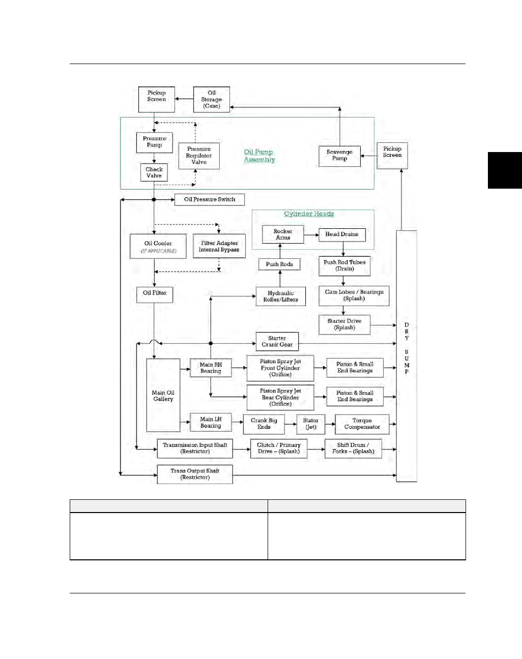
OOIILL FFLLOOW
W DDIIAAGGRRAAM
M
OIL COOLER
FILTER ADAPTER INTERNAL BYPASS
• Chieftain Dark Horse
• Chieftain
• Roadmaster
• Chief Classic
• Chief Vintage
• Chief Dark Horse
• Springfield
|
|
|
3.25 OOIILL FFLLOOW W DDIIAAGGRRAAM M OIL COOLER FILTER ADAPTER INTERNAL BYPASS • Chieftain Dark Horse • Chief Classic |