Indian motorcycle 2017. Service Manual - page 7


  Главная      Manuals     Indian motorcycle 2017. Service Manual


Search            copyright infringement  


Content      ..     5      6      7      8     ..


Indian motorcycle 2017. Service Manual - page 7


2

2.33

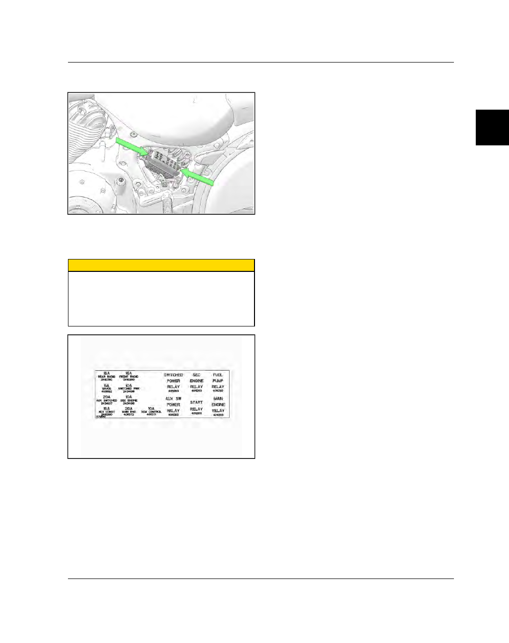
2. Squeeze fuse box tabs together as shown and lift

cover off of fuse box.

3. If any fuse is blown, turn off main switch. Install

new fuse of specified amperage. Turn on switches
and see if system operates correctly. Repeat fuse
failure indicates an electrical problem.

CAUTION

Do not use fuses of a higher amperage rating than

what is specified.

If the correctly rated fuse continues to blow,

something is wrong and needs to be corrected.

Substituting a higher amperage fuse can lead to

extensive electrical system and vehicle damage.

MAINTENANCE

2.34

9927618 R03 - 2017 Indian Motorcycle (Full-Size) Service Manual

HHEEAADDLLIIGGHHTT AAIIM

M IINNSSPPEECCTTIIOONN

Adjust headlight aim when there is a change in load
(rider, cargo, accessories, etc.) or after suspension
adjustment.

CHIEF CLASSIC / CHIEF VINTAGE / CHIEF DARK
HORSE / CHIEFTAIN DARK HORSE / CHIEFTAIN /
SPRINGFIELD:

With the headlight switched to HIGH

beam, the center of highest intensity (appears as a
diamond shape) should be 7.5 in (19 cm) below the
height of the headlight bulb when centered straight
ahead at 25 feet (7.62 m).

ROADMASTER / ROADMASTER CLASSIC:

With the

headlight switched to LOW beam, the top of the
highest intensity (appears as a diamond shape) should
be 3.0 in (7.6 cm) below the height of the headlight
bulb when centered straight ahead at 25 feet (7.62 m).

Follow all steps below to ensure accurate aim
inspection.

1. Check and adjust the tire pressure. See Tire

Pressure / Specifications, page 2.11.

2. Verify suspension ride height is set correctly. See

Rear Shock Preload Inspection, page 2.37.

3. Move the motorcycle to a clear area with a level

floor and dim lighting, and place it so the top front
edge of the headlight housing is 25 ft. (7.6 m) from
the wall.

4. Have the rider (and passenger if normally present)

straddle the motorcycle in an upright position and
sit in the seat (s). Center the handlebars in a
straight ahead position.

5. Turn ignition switch ON.

6. Set headlight to HIGH beam and LOW beam for

models listed below.

7. Compare the position of headlight beam on the

wall

to

the

illustration

below

and

adjust

if

necessary.

HIGH

BEAM

CHIEF CLASSIC / CHIEF VINTAGE / CHIEF DARK HORSE / CHIEFTAIN DARK HORSE /

CHIEFTAIN / SPRINGFIELD

MAINTENANCE

2

2.35

LOW

BEAM

ROADMASTER

HHEEAADDLLIIGGHHTT AAIIM

M AADDJJUUSSTTM

MEENNTT

NOTE

Chieftain / Roadmaster models:

Access headlight

adjustment fasteners by removing the headlight

bezel. See Headlight Bulb Replacement - All Models,

page 10.52.

Classic / Vintage / Dark Horse / Springfield

models:

Headlight adjustment fasteners can be

accessed directly through the headlight nacelle. It is

not necessary to remove the nacelle for adjustment.

1. To adjust the headlight vertically, both adjustment

fasteners

q

must be turned in or out equally. Turn

fasteners in (clockwise) to lower the beam. Turn
fasteners out (counter-clockwise) to raise the
beam.

2. To adjust the headlight horizontally, turn the left

adjustment fastener out (counter-clockwise) to
adjust the beam to the left. Turn the right
adjustment fastener out (counter-clockwise) to
adjust the beam to the right.

MAINTENANCE

2.36

9927618 R03 - 2017 Indian Motorcycle (Full-Size) Service Manual

SSIIDDEESSTTAANNDD IINNSSPPEECCTTIIOONN

1.

Support the motorcycle in an upright position with
the front wheel clamped in a wheel vise.

2.

Inspect sidestand spring for damage or loss of
tension. Be sure stand returns to fully retracted
position.

3.

Inspect side stand for smooth movement.

4.

Inspect sidestand pivot fastener nut for proper
torque.

TORQUE

Sidestand Pivot Fastener:

37 ft-lbs (50 Nm)

5.

Replace sidestand if it is bent. Do not attempt to
straighten sidestand.

SSIIDDEESSTTAANNDD RREEM

MOOVVAALL // IINNSSTTAALLLLAATTIIOONN

WARNING

The sidestand spring is under tension. Wear eye and

face protection when removing and installing the

spring and sidestand. Be sure the vehicle is properly

secured before you begin.

IMPORTANT

Sidestand fasteners must be replaced any time the

sidestand is removed. The nut is a crushed lock and

therefor it can not be reused.

1.

Sidestand

will

be

moved

between

the

UP

(retracted) and DOWN (extended) position during
removal and installation. Be sure vehicle is
properly secured.

2.

Remove sidestand pivot fastener

q

using a 6mm

hex wrench while holding the nut with a 15 mm
wrench.

3.

Grasp sidestand firmly and move it to the UP
position.

4.

Pull sidestand rearward against spring tension
until mounting flange on sidestand is clear of the
mounting boss on the frame.

5.

Relax tension and remove spring.

6.

Installation:

Attach spring to sidestand.

7.

Lightly grease sidestand mounting boss on frame
and the shouldered portion of the pivot fastener.

8.

Place loose end of spring through hole in frame
rail.

9.

With sidestand in the retracted position (up), pull
stand rearward against spring tension until the
mounting flange on the sidestand drops onto the
mounting boss on the frame.

10. Swing sidestand to the extended position to align

fastener hole and install

NEW

fastener and nut.

11. Torque to specification and wipe off any excess

grease.

TORQUE

Sidestand Pivot Fastener:

37 ft-lbs (50 Nm)

12. Cycle the sidestand to be sure it moves freely, and

returns to the fully retracted position.

SSTTEEEERRIINNGG HHEEAADD // FFRROONNTT W

WHHEEEELL IINNSSPPEECCTTIIOONN

WARNING

Care should be taken to be sure the motorcycle will

not tip or fall while elevated. Severe personal injury

or death may occur if the motorcycle tips or falls.

NOTE

Be sure control cables, hoses and wiring are not

interfering with handle bar rotation.

1.

Secure motorcycle with front wheel off the floor.

2.

Turn handlebars from full left to full right and
inspect for smooth, free movement. Point front
wheel straight ahead, grasp fork tubes and pull/
push fork tubes back and forth. If steering binds,
feels rough or uneven, or if movement is detected
at steering stem, adjust or replace steering head
bearings as necessary. See

3.

Rotate front wheel and inspect for smooth rotation
of front wheel bearings. If roughness or unusual
sounds are present, replace front wheel bearings.
See Steering / Suspension chapter.

MAINTENANCE

2

2.37

4.

Turn handle bars full right or left and hold against
the fork stop. Attempt to move front wheel side-to-
side. If movement is observed, inspect front axle,
wheel, and bearings. See Steering / Suspension
chapter.

SSW

WIINNGGAARRM

M IINNSSPPEECCTTIIOONN

WARNING

Care should be taken to be sure the motorcycle will
not tip or fall while elevated. Severe personal injury

or death may occur if the motorcycle tips or falls.

1.

Sit astride the motorcycle. Compress the rear
suspension several times and check for smooth
and quiet operation

w

.

2.

Secure motorcycle with rear wheel elevated.

3.

Inspect for worn swing arm bearings by grasping
the rear wheel and attempting to move wheel side-
to-side

q

.

4.

If movement is detected, determine if movement is
at axle area

e

or swingarm pivot area

r

. Refer to

Steering / Suspension chapter for wheel bearing
and swingarm bearing replacement.

5.

Rotate rear wheel and inspect for smooth rotation
of rear wheel bearings. If roughness or unusual
sounds are detected, inspect rear wheel bearings,
belt tension and alignment, and brake pads.

6.

Inspect rear shock for leakage and all rear
suspension components for damage or loose
fasteners.

7.

Inspect suspension pivots and shock mounts for
radial movement in all pivot joints. If a joint has
radial movement, remove rear shock absorber and
inspect suspension pivot linkage. See Steering /
Suspension chapter.

8.

Verify axle nut is tight.

9.

Replace any worn or damaged parts.

RREEAARR SSHHOOCCKK PPRREELLOOAADD IINNSSPPEECCTTIIOONN

Periodically inspect rear shock preload. For the most
comfortable ride and proper ground clearance, adjust
preload if ride height is out of specification.

1. Verify that tire pressure is at specification. See Tire

Pressure / Specifications, page 2.11.

2. Place the motorcycle in an upright position with the

front wheel clamped in a wheel vise.

3. Remove saddlebags, if equipped.

4. Apply a strip of removable tape

q

to the rear

fender directly over the center of the rear axle.

5.

CAUTION

For CALIFORNIA and INTERNATIONAL motorcycles,

the Evaporative Canister must be removed prior to

raising the motorcycle. If the canister is not removed

and the motorcycle is raised, the fittings will contact

the swingarm and become damaged.

Using a scissor jack or similar tool, raise the
motorcycle until the rear shock is completely
extended.

MAINTENANCE

2.38

9927618 R03 - 2017 Indian Motorcycle (Full-Size) Service Manual

6. Measure the distance (in millimeters) from the

center of the rear axle

w

to the bottom of the tape

e

. Record the results as measurement M1.

7. Lower the motorcycle and remove the scissor jack.

8. Load the motorcycle with all intended cargo.

Wearing riding gear, sit on the motorcycle in the
normal riding position.

IMPORTANT

Have an assistant stabilize the motorcycle in a

vertical position so rider can sit in a normal riding

position with feet on floorboards.

9. Have an assistant measure the same location.

Record the results as measurement M2.

10. Subtract measurement M2 from M1. The result is

the measured rider sag. (M1–M2=Sag)

11. Adjust preload as needed to achieve suspension

sag indicated in the table below. SeeRear Shock
Preload Adjustment - Chief Models, page 2.38 
or
Rear Shock Preload Adjustment - Springfield /
Chieftain / Roadmaster, page 2.39 
for adjustment
procedure.

RECOMMENDED SUSPENSION SAG

Chief Classic / Chief
Vintage / Chief Dark
Horse

35 mm

Springfield / Chieftain
Dark Horse / Chieftain /
Roadmaster

45 mm

RREEAARR SSHHOOCCKK PPRREELLOOAADD AADDJJUUSSTTM

MEENNTT -- CCHHIIEEFF

M

MOODDEELLSS

1. Place the motorcycle in an upright position with the

front wheel clamped in a wheel vise.

2. Remove the seat as outlined in Frame / Body

chapter.

3. Using shock spanner wrench

(PV-46993)

loosen the

lock nut by turning it counter-clockwise (as viewed
from the top of the shock).

4. Spray a light lubricant on the adjuster nut where it

contacts the spring.

5. Adjust shock preload by rotating the adjuster nut

clockwise (as viewed from the top of the shock) to

INCREASE

preload (firm) or counter-clockwise to

DECREASE

preload (softer).

6. Recheck the preload measurement after adjusting.

7. Tighten the lock nut securely against the adjuster

nut.

8. Install the seat as outlined in Frame / Body chapter.

MAINTENANCE

2

2.39

RREEAARR SSHHOOCCKK PPRREELLOOAADD AADDJJUUSSTTM

MEENNTT -- SSPPRRIINNGGFFIIEELLDD // CCHHIIEEFFTTAAIINN // RROOAADDM

MAASSTTEERR

Refer to the label located on the inside of the left side
cover. The label shows recommended pressures
based on potential load weights. Always inspect and

adjust shock preload (ride height) based on your
actual load weight.

AIR SUSPENSION ADJUSTMENT

TOTAL CARGO &

OCCUPANT WEIGHT (LB)

AIR PRESSURE (PSI)

MAX PRESSURE: 150 PSI

NO TRUNK

LEATHER

TRUNK

PAINTED

TRUNK

0

0

0

0

SELECT PRESSURE

CORRESPONDING TO TOTAL

CARGO AND OCCUPANT WEIGHT.

REMOVE ALL PASSENGERS AND

CARGO BEFORE SETTING /

CHECKING SHOCK PRESSURE. SET

PRESSURE WITH BIKE ON SIDE

STAND.

150

0

0

0

175

0

0

10

200

0

10

23

225

10

23

30

250

23

30

38

275

30

38

48

300

38

48

60

325

48

60

71

350

60

71

85

375

71

85

100

400

85

100

122

425

100

122

134

450

122

134

145

475

134

145

NA

500

145

NA

NA

IMPORTANT

Follow these guidelines when adjusting:

• Park motorcycle with the sidestand down on a firm,

level surface.

• Remove all riders and cargo.

DO NOT exceed 150 psi (1034 kPa) in the shock.

• Use shock air pump

(PV-48909)

to complete

adjustment procedure.

1. Remove the LH upper side cover. See Side Cover

(Upper), Removal / Installation, page 7.17.

2. Remove the cap from the air fitting

q

.

3. Refer to the label on the inside of the LH side cover

to determine the recommended shock air pressure.

4. Install the hose fitting the shock air pump onto the

fitting and read the gauge.

5. To reduce air pressure, push the bleed button on

the gauge. Release air until the desired pressure
reading is obtained.

MAINTENANCE

2.40

9927618 R03 - 2017 Indian Motorcycle (Full-Size) Service Manual

6. To increase pressure, pump the handle until

pressure increases to the desired level.

7. Remove the hose from the air fitting and reinstall

the cap.

8. Repeat the preload inspection to verify proper

preload. See Rear Shock Preload Inspection, page
2.37.

M

MAAIINNTTEENNAANNCCEE -- CCHHEECCKK W

WHHEEEELL SSPPOOKKEESS

If your motorcycle is equipped with spoked wheels,
inspect both wheels for loose, bent, broken or missing
spokes. To identify loose spokes, grasp each spoke
and try to move it side to side or up and down. All
spokes should be equally tight and have the same
amount of flex. Tighten loose spokes or replace bent,
broken or missing spokes.

Inspect spokes after first 500 miles, then again every

5,000 miles.

MAINTENANCE

3

3.1

ENGINE / COOLING / EXHAUST

CHAPTER 3

ENGINE / COOLING / EXHAUST

AIR CLEANER SERVICE . . . . . . . . . . . . . . . . . . . . . . . . . . . . . . . . . . . . . . . . . . . . . . . . . . . . . . . . . . . . . . . . . . . . . . . . . . . . . . . . . 3.4

AIR BOX REMOVAL

. . . . . . . . . . . . . . . . . . . . . . . . . . . . . . . . . . . . . . . . . . . . . . . . . . . . . . . . . . . . . . . . . . . . . . . . . . . . . . . . . . . . 3.4

AIR BOX INSTALLATION

. . . . . . . . . . . . . . . . . . . . . . . . . . . . . . . . . . . . . . . . . . . . . . . . . . . . . . . . . . . . . . . . . . . . . . . . . . . . . . . 3.5

ENGINE REMOVAL / INSTALL. . . . . . . . . . . . . . . . . . . . . . . . . . . . . . . . . . . . . . . . . . . . . . . . . . . . . . . . . . . . . . . . . . . . . . . . . . . 3.7

GENERAL INFORMATION

. . . . . . . . . . . . . . . . . . . . . . . . . . . . . . . . . . . . . . . . . . . . . . . . . . . . . . . . . . . . . . . . . . . . . . . . . . . . . 3.7

SERVICE NOTES

. . . . . . . . . . . . . . . . . . . . . . . . . . . . . . . . . . . . . . . . . . . . . . . . . . . . . . . . . . . . . . . . . . . . . . . . . . . . . . . . . 3.7

SERVICE SPECIFICATIONS

. . . . . . . . . . . . . . . . . . . . . . . . . . . . . . . . . . . . . . . . . . . . . . . . . . . . . . . . . . . . . . . . . . . . . . 3.7

TORQUE SPECIFICATIONS

. . . . . . . . . . . . . . . . . . . . . . . . . . . . . . . . . . . . . . . . . . . . . . . . . . . . . . . . . . . . . . . . . . . . . . . 3.7

SPECIAL TOOLS

. . . . . . . . . . . . . . . . . . . . . . . . . . . . . . . . . . . . . . . . . . . . . . . . . . . . . . . . . . . . . . . . . . . . . . . . . . . . . . . . . . 3.8

ASSEMBLY VIEWS

. . . . . . . . . . . . . . . . . . . . . . . . . . . . . . . . . . . . . . . . . . . . . . . . . . . . . . . . . . . . . . . . . . . . . . . . . . . . . . . . . . . . . 3.9

ENGINE BRACKETS / FASTENERS

. . . . . . . . . . . . . . . . . . . . . . . . . . . . . . . . . . . . . . . . . . . . . . . . . . . . . . . . . . . . . . . . 3.9

LEFT SIDE BRACKETS / FASTENERS

. . . . . . . . . . . . . . . . . . . . . . . . . . . . . . . . . . . . . . . . . . . . . . . . . . . . . . . . . . . . . . 3.9

RIGHT SIDE BRACKETS / FASTENERS

. . . . . . . . . . . . . . . . . . . . . . . . . . . . . . . . . . . . . . . . . . . . . . . . . . . . . . . . . . .3.10

ENGINE REMOVAL

. . . . . . . . . . . . . . . . . . . . . . . . . . . . . . . . . . . . . . . . . . . . . . . . . . . . . . . . . . . . . . . . . . . . . . . . . . . . . . . . . . .3.11

PREPARATION FOR ENGINE REMOVAL

. . . . . . . . . . . . . . . . . . . . . . . . . . . . . . . . . . . . . . . . . . . . . . . . . . . . . . . . .3.11

REMOVING ENGINE FROM FRAME

. . . . . . . . . . . . . . . . . . . . . . . . . . . . . . . . . . . . . . . . . . . . . . . . . . . . . . . . . . . . .3.12

ENGINE INSTALLATION

. . . . . . . . . . . . . . . . . . . . . . . . . . . . . . . . . . . . . . . . . . . . . . . . . . . . . . . . . . . . . . . . . . . . . . . . . . . . . .3.17

LUBRICATION / COOLING . . . . . . . . . . . . . . . . . . . . . . . . . . . . . . . . . . . . . . . . . . . . . . . . . . . . . . . . . . . . . . . . . . . . . . . . . . . . .3.21

GENERAL INFORMATION

. . . . . . . . . . . . . . . . . . . . . . . . . . . . . . . . . . . . . . . . . . . . . . . . . . . . . . . . . . . . . . . . . . . . . . . . . . . .3.21

SERVICE NOTES

. . . . . . . . . . . . . . . . . . . . . . . . . . . . . . . . . . . . . . . . . . . . . . . . . . . . . . . . . . . . . . . . . . . . . . . . . . . . . . . .3.21

TROUBLESHOOTING

. . . . . . . . . . . . . . . . . . . . . . . . . . . . . . . . . . . . . . . . . . . . . . . . . . . . . . . . . . . . . . . . . . . . . . . . . . . .3.21

SPECIAL TOOLS

. . . . . . . . . . . . . . . . . . . . . . . . . . . . . . . . . . . . . . . . . . . . . . . . . . . . . . . . . . . . . . . . . . . . . . . . . . . . . . . . .3.21

TORQUE SPECIFICATIONS

. . . . . . . . . . . . . . . . . . . . . . . . . . . . . . . . . . . . . . . . . . . . . . . . . . . . . . . . . . . . . . . . . . . . . .3.22

SERVICE SPECIFICATIONS

. . . . . . . . . . . . . . . . . . . . . . . . . . . . . . . . . . . . . . . . . . . . . . . . . . . . . . . . . . . . . . . . . . . . .3.22

ASSEMBLY VIEWS

. . . . . . . . . . . . . . . . . . . . . . . . . . . . . . . . . . . . . . . . . . . . . . . . . . . . . . . . . . . . . . . . . . . . . . . . . . . . . . . . . . . .3.23

OIL COOLER

. . . . . . . . . . . . . . . . . . . . . . . . . . . . . . . . . . . . . . . . . . . . . . . . . . . . . . . . . . . . . . . . . . . . . . . . . . . . . . . . . . . .3.23

FILTER ADAPTER

. . . . . . . . . . . . . . . . . . . . . . . . . . . . . . . . . . . . . . . . . . . . . . . . . . . . . . . . . . . . . . . . . . . . . . . . . . . . . . . .3.24

OIL FLOW DIAGRAM

. . . . . . . . . . . . . . . . . . . . . . . . . . . . . . . . . . . . . . . . . . . . . . . . . . . . . . . . . . . . . . . . . . . . . . . . . . . .3.25

LUBRICATION SYSTEM

. . . . . . . . . . . . . . . . . . . . . . . . . . . . . . . . . . . . . . . . . . . . . . . . . . . . . . . . . . . . . . . . . . . . . . . . . .3.26

OIL PRESSURE INSPECTION

. . . . . . . . . . . . . . . . . . . . . . . . . . . . . . . . . . . . . . . . . . . . . . . . . . . . . . . . . . . . . . . . . . . . . . . . . .3.27

OIL PRESSURE

. . . . . . . . . . . . . . . . . . . . . . . . . . . . . . . . . . . . . . . . . . . . . . . . . . . . . . . . . . . . . . . . . . . . . . . . . . . . . . . . . .3.27

OIL PUMP SERVICE

. . . . . . . . . . . . . . . . . . . . . . . . . . . . . . . . . . . . . . . . . . . . . . . . . . . . . . . . . . . . . . . . . . . . . . . . . . . . . . . . . .3.28

OIL PUMP REMOVAL

. . . . . . . . . . . . . . . . . . . . . . . . . . . . . . . . . . . . . . . . . . . . . . . . . . . . . . . . . . . . . . . . . . . . . . . . . . . .3.28

OIL PUMP INSTALLATION

. . . . . . . . . . . . . . . . . . . . . . . . . . . . . . . . . . . . . . . . . . . . . . . . . . . . . . . . . . . . . . . . . . . . . . .3.29

OIL COOLER SERVICE

. . . . . . . . . . . . . . . . . . . . . . . . . . . . . . . . . . . . . . . . . . . . . . . . . . . . . . . . . . . . . . . . . . . . . . . . . . . . . . .3.30

OIL COOLER REMOVAL

. . . . . . . . . . . . . . . . . . . . . . . . . . . . . . . . . . . . . . . . . . . . . . . . . . . . . . . . . . . . . . . . . . . . . . . . .3.30

OIL COOLER INSPECTION

. . . . . . . . . . . . . . . . . . . . . . . . . . . . . . . . . . . . . . . . . . . . . . . . . . . . . . . . . . . . . . . . . . . . . .3.30

OIL COOLER INSTALLATION

. . . . . . . . . . . . . . . . . . . . . . . . . . . . . . . . . . . . . . . . . . . . . . . . . . . . . . . . . . . . . . . . . . . .3.31

CYLINDER HEAD / VALVES . . . . . . . . . . . . . . . . . . . . . . . . . . . . . . . . . . . . . . . . . . . . . . . . . . . . . . . . . . . . . . . . . . . . . . . . . . . .3.32

GENERAL INFORMATION

. . . . . . . . . . . . . . . . . . . . . . . . . . . . . . . . . . . . . . . . . . . . . . . . . . . . . . . . . . . . . . . . . . . . . . . . . . . .3.32

SERVICE NOTES

. . . . . . . . . . . . . . . . . . . . . . . . . . . . . . . . . . . . . . . . . . . . . . . . . . . . . . . . . . . . . . . . . . . . . . . . . . . . . . . .3.32

SPECIAL TOOLS

. . . . . . . . . . . . . . . . . . . . . . . . . . . . . . . . . . . . . . . . . . . . . . . . . . . . . . . . . . . . . . . . . . . . . . . . . . . . . . . . .3.32

3.2

9927618 R03 - 2017 Indian Motorcycle (Full-Size) Service Manual

TORQUE SPECIFICATIONS

. . . . . . . . . . . . . . . . . . . . . . . . . . . . . . . . . . . . . . . . . . . . . . . . . . . . . . . . . . . . . . . . . . . . . . . . . . .3.33

SERVICE SPECIFICATIONS

. . . . . . . . . . . . . . . . . . . . . . . . . . . . . . . . . . . . . . . . . . . . . . . . . . . . . . . . . . . . . . . . . . . . . . . . . .3.33

ASSEMBLY VIEWS

. . . . . . . . . . . . . . . . . . . . . . . . . . . . . . . . . . . . . . . . . . . . . . . . . . . . . . . . . . . . . . . . . . . . . . . . . . . . . . . . . . . . . . . . .3.36

CAM CHAIN

. . . . . . . . . . . . . . . . . . . . . . . . . . . . . . . . . . . . . . . . . . . . . . . . . . . . . . . . . . . . . . . . . . . . . . . . . . . . . . . . . . . . . . . . .3.36

CAMSHAFTS

. . . . . . . . . . . . . . . . . . . . . . . . . . . . . . . . . . . . . . . . . . . . . . . . . . . . . . . . . . . . . . . . . . . . . . . . . . . . . . . . . . . . . . . . .3.37

LIFTERS / PUSHRODS

. . . . . . . . . . . . . . . . . . . . . . . . . . . . . . . . . . . . . . . . . . . . . . . . . . . . . . . . . . . . . . . . . . . . . . . . . . . . . . . .3.38

CYLINDER HEAD

. . . . . . . . . . . . . . . . . . . . . . . . . . . . . . . . . . . . . . . . . . . . . . . . . . . . . . . . . . . . . . . . . . . . . . . . . . . . . . . . . . . . .3.39

CAMSHAFT TIMING

. . . . . . . . . . . . . . . . . . . . . . . . . . . . . . . . . . . . . . . . . . . . . . . . . . . . . . . . . . . . . . . . . . . . . . . . . . . . . . . . . .3.40

CAM CHAIN SERVICE

. . . . . . . . . . . . . . . . . . . . . . . . . . . . . . . . . . . . . . . . . . . . . . . . . . . . . . . . . . . . . . . . . . . . . . . . . . . . . . . . . . . . .3.41

LOCKING THE CRANKSHAFT FOR SERVICE

. . . . . . . . . . . . . . . . . . . . . . . . . . . . . . . . . . . . . . . . . . . . . . . . . . . . . . . . .3.41

CAM CHAIN COVER REMOVAL / INSTALLATION

. . . . . . . . . . . . . . . . . . . . . . . . . . . . . . . . . . . . . . . . . . . . . . . . . . . .3.41

CAM CHAIN TENSIONER REMOVAL

. . . . . . . . . . . . . . . . . . . . . . . . . . . . . . . . . . . . . . . . . . . . . . . . . . . . . . . . . . . . . . . . .3.42

CAM CHAIN TENSIONER INSPECTION

. . . . . . . . . . . . . . . . . . . . . . . . . . . . . . . . . . . . . . . . . . . . . . . . . . . . . . . . . . . . . . .3.42

CAM CHAIN TENSIONER INSTALLATION

. . . . . . . . . . . . . . . . . . . . . . . . . . . . . . . . . . . . . . . . . . . . . . . . . . . . . . . . . . . .3.42

CAM CHAIN GUIDE REMOVAL

. . . . . . . . . . . . . . . . . . . . . . . . . . . . . . . . . . . . . . . . . . . . . . . . . . . . . . . . . . . . . . . . . . . . . . .3.43

CAM CHAIN GUIDE INSTALLATION

. . . . . . . . . . . . . . . . . . . . . . . . . . . . . . . . . . . . . . . . . . . . . . . . . . . . . . . . . . . . . . . . . .3.43

CAM CHAIN REMOVAL

. . . . . . . . . . . . . . . . . . . . . . . . . . . . . . . . . . . . . . . . . . . . . . . . . . . . . . . . . . . . . . . . . . . . . . . . . . . . . .3.43

CAM CHAIN INSTALLATION

. . . . . . . . . . . . . . . . . . . . . . . . . . . . . . . . . . . . . . . . . . . . . . . . . . . . . . . . . . . . . . . . . . . . . . . . .3.44

CAMSHAFT / LIFTER SERVICE - ENGINE OUT

. . . . . . . . . . . . . . . . . . . . . . . . . . . . . . . . . . . . . . . . . . . . . . . . . . . . . . . . . . . .3.45

LIFTER REMOVAL

. . . . . . . . . . . . . . . . . . . . . . . . . . . . . . . . . . . . . . . . . . . . . . . . . . . . . . . . . . . . . . . . . . . . . . . . . . . . . . . . . . . .3.45

LIFTER INSTALLATION

. . . . . . . . . . . . . . . . . . . . . . . . . . . . . . . . . . . . . . . . . . . . . . . . . . . . . . . . . . . . . . . . . . . . . . . . . . . . . . .3.46

CAMSHAFT CARRIER REMOVAL

. . . . . . . . . . . . . . . . . . . . . . . . . . . . . . . . . . . . . . . . . . . . . . . . . . . . . . . . . . . . . . . . . . . . .3.47

CAMSHAFT CARRIER DISASSEMBLY

. . . . . . . . . . . . . . . . . . . . . . . . . . . . . . . . . . . . . . . . . . . . . . . . . . . . . . . . . . . . . . . . .3.47

CAMSHAFT INSPECTION

. . . . . . . . . . . . . . . . . . . . . . . . . . . . . . . . . . . . . . . . . . . . . . . . . . . . . . . . . . . . . . . . . . . . . . . . . . . .3.49

CAMSHAFT CARRIER ASSEMBLY

. . . . . . . . . . . . . . . . . . . . . . . . . . . . . . . . . . . . . . . . . . . . . . . . . . . . . . . . . . . . . . . . . . . . .3.50

CAMSHAFT CARRIER INSTALLATION

. . . . . . . . . . . . . . . . . . . . . . . . . . . . . . . . . . . . . . . . . . . . . . . . . . . . . . . . . . . . . . . .3.53

CAMSHAFT SERVICE - IN BIKE

. . . . . . . . . . . . . . . . . . . . . . . . . . . . . . . . . . . . . . . . . . . . . . . . . . . . . . . . . . . . . . . . . . . . . . . . . . . .3.54

CAMSHAFT REMOVAL

. . . . . . . . . . . . . . . . . . . . . . . . . . . . . . . . . . . . . . . . . . . . . . . . . . . . . . . . . . . . . . . . . . . . . . . . . . . . . . .3.54

CAMSHAFT INSTALLATION

. . . . . . . . . . . . . . . . . . . . . . . . . . . . . . . . . . . . . . . . . . . . . . . . . . . . . . . . . . . . . . . . . . . . . . . . . .3.58

CYLINDER HEAD SERVICE

. . . . . . . . . . . . . . . . . . . . . . . . . . . . . . . . . . . . . . . . . . . . . . . . . . . . . . . . . . . . . . . . . . . . . . . . . . . . . . . .3.59

VALVE COVER REMOVAL

. . . . . . . . . . . . . . . . . . . . . . . . . . . . . . . . . . . . . . . . . . . . . . . . . . . . . . . . . . . . . . . . . . . . . . . . . . . .3.59

VALVE COVER INSTALLATION

. . . . . . . . . . . . . . . . . . . . . . . . . . . . . . . . . . . . . . . . . . . . . . . . . . . . . . . . . . . . . . . . . . . . . . .3.60

CYLINDER HEAD REMOVAL

. . . . . . . . . . . . . . . . . . . . . . . . . . . . . . . . . . . . . . . . . . . . . . . . . . . . . . . . . . . . . . . . . . . . . . . . .3.61

ROCKER ARM REMOVAL

. . . . . . . . . . . . . . . . . . . . . . . . . . . . . . . . . . . . . . . . . . . . . . . . . . . . . . . . . . . . . . . . . . . . . . . . . . . . .3.61

ROCKER ARM INSPECTION

. . . . . . . . . . . . . . . . . . . . . . . . . . . . . . . . . . . . . . . . . . . . . . . . . . . . . . . . . . . . . . . . . . . . . . . . . .3.62

CYLINDER HEAD DISASSEMBLY

. . . . . . . . . . . . . . . . . . . . . . . . . . . . . . . . . . . . . . . . . . . . . . . . . . . . . . . . . . . . . . . . . . . . .3.62

CYLINDER HEAD INSPECTION

. . . . . . . . . . . . . . . . . . . . . . . . . . . . . . . . . . . . . . . . . . . . . . . . . . . . . . . . . . . . . . . . . . . . . . .3.63

VALVE SPRING FREE LENGTH INSPECTION

. . . . . . . . . . . . . . . . . . . . . . . . . . . . . . . . . . . . . . . . . . . . . . . . . . . . . . . . . .3.63

VALVE INSPECTION

. . . . . . . . . . . . . . . . . . . . . . . . . . . . . . . . . . . . . . . . . . . . . . . . . . . . . . . . . . . . . . . . . . . . . . . . . . . . . . . . . .3.64

VALVE INSPECTION

. . . . . . . . . . . . . . . . . . . . . . . . . . . . . . . . . . . . . . . . . . . . . . . . . . . . . . . . . . . . . . . . . . . . . . . . . . . . . . . . . .3.65

VALVE GUIDE REMOVAL / INSTALLATION

. . . . . . . . . . . . . . . . . . . . . . . . . . . . . . . . . . . . . . . . . . . . . . . . . . . . . . . . . . .3.66

VALVE SEAT INSPECTION

. . . . . . . . . . . . . . . . . . . . . . . . . . . . . . . . . . . . . . . . . . . . . . . . . . . . . . . . . . . . . . . . . . . . . . . . . . . .3.66

VALVE SEAT RECONDITIONING

. . . . . . . . . . . . . . . . . . . . . . . . . . . . . . . . . . . . . . . . . . . . . . . . . . . . . . . . . . . . . . . . . . . . .3.66

CYLINDER HEAD ASSEMBLY

. . . . . . . . . . . . . . . . . . . . . . . . . . . . . . . . . . . . . . . . . . . . . . . . . . . . . . . . . . . . . . . . . . . . . . . . .3.67

CYLINDER HEAD INSTALLATION

. . . . . . . . . . . . . . . . . . . . . . . . . . . . . . . . . . . . . . . . . . . . . . . . . . . . . . . . . . . . . . . . . . . .3.67

TROUBLESHOOTING, CYLINDER HEAD AND VALVE TRAIN

. . . . . . . . . . . . . . . . . . . . . . . . . . . . . . . . . . . . . . . . . .3.69

CYLINDER / PISTON . . . . . . . . . . . . . . . . . . . . . . . . . . . . . . . . . . . . . . . . . . . . . . . . . . . . . . . . . . . . . . . . . . . . . . . . . . . . . . . . . . . . . . . . .3.72

ENGINE / COOLING / EXHAUST

3

3.3

GENERAL INFORMATION

. . . . . . . . . . . . . . . . . . . . . . . . . . . . . . . . . . . . . . . . . . . . . . . . . . . . . . . . . . . . . . . . . . . . . . . . . . . . . . . . .3.72

SERVICE NOTES

. . . . . . . . . . . . . . . . . . . . . . . . . . . . . . . . . . . . . . . . . . . . . . . . . . . . . . . . . . . . . . . . . . . . . . . . . . . . . . . . . . . . .3.72

SPECIAL TOOLS

. . . . . . . . . . . . . . . . . . . . . . . . . . . . . . . . . . . . . . . . . . . . . . . . . . . . . . . . . . . . . . . . . . . . . . . . . . . . . . . . . . . . . .3.72

TORQUE SPECIFICATIONS

. . . . . . . . . . . . . . . . . . . . . . . . . . . . . . . . . . . . . . . . . . . . . . . . . . . . . . . . . . . . . . . . . . . . . . . . . . .3.72

SERVICE SPECIFICATIONS

. . . . . . . . . . . . . . . . . . . . . . . . . . . . . . . . . . . . . . . . . . . . . . . . . . . . . . . . . . . . . . . . . . . . . . . . . .3.73

ASSEMBLY VIEWS

. . . . . . . . . . . . . . . . . . . . . . . . . . . . . . . . . . . . . . . . . . . . . . . . . . . . . . . . . . . . . . . . . . . . . . . . . . . . . . . . . . . . . . . . .3.74

CYLINDER / PISTON

. . . . . . . . . . . . . . . . . . . . . . . . . . . . . . . . . . . . . . . . . . . . . . . . . . . . . . . . . . . . . . . . . . . . . . . . . . . . . . . . .3.74

CYLINDER / PISTON SERVICE

. . . . . . . . . . . . . . . . . . . . . . . . . . . . . . . . . . . . . . . . . . . . . . . . . . . . . . . . . . . . . . . . . . . . . . . . . . . .3.75

PISTON RING PROFILE AND ORIENTATION

. . . . . . . . . . . . . . . . . . . . . . . . . . . . . . . . . . . . . . . . . . . . . . . . . . . . . . . . . .3.75

CYLINDER REMOVAL

. . . . . . . . . . . . . . . . . . . . . . . . . . . . . . . . . . . . . . . . . . . . . . . . . . . . . . . . . . . . . . . . . . . . . . . . . . . . . . . .3.76

CYLINDER INSPECTION

. . . . . . . . . . . . . . . . . . . . . . . . . . . . . . . . . . . . . . . . . . . . . . . . . . . . . . . . . . . . . . . . . . . . . . . . . . . . .3.76

CYLINDER BORE MEASUREMENT

. . . . . . . . . . . . . . . . . . . . . . . . . . . . . . . . . . . . . . . . . . . . . . . . . . . . . . . . . . . . . . . . . . . .3.76

PISTON TO CYLINDER CLEARANCE WORKSHEET

. . . . . . . . . . . . . . . . . . . . . . . . . . . . . . . . . . . . . . . . . . . . . . . . . . .3.77

CYLINDER WARPAGE MEASUREMENT

. . . . . . . . . . . . . . . . . . . . . . . . . . . . . . . . . . . . . . . . . . . . . . . . . . . . . . . . . . . . . . .3.78

PISTON & PISTON RING REMOVAL

. . . . . . . . . . . . . . . . . . . . . . . . . . . . . . . . . . . . . . . . . . . . . . . . . . . . . . . . . . . . . . . . . . .3.78

PISTON & PISTON RING INSPECTION

. . . . . . . . . . . . . . . . . . . . . . . . . . . . . . . . . . . . . . . . . . . . . . . . . . . . . . . . . . . . . . . .3.79

PISTON PIN / PIN BORE INSPECTION

. . . . . . . . . . . . . . . . . . . . . . . . . . . . . . . . . . . . . . . . . . . . . . . . . . . . . . . . . . . . . . . .3.80

PISTON RING INSTALLATION

. . . . . . . . . . . . . . . . . . . . . . . . . . . . . . . . . . . . . . . . . . . . . . . . . . . . . . . . . . . . . . . . . . . . . . . .3.80

PISTON INSTALLATION

. . . . . . . . . . . . . . . . . . . . . . . . . . . . . . . . . . . . . . . . . . . . . . . . . . . . . . . . . . . . . . . . . . . . . . . . . . . . . .3.81

CYLINDER STUD REPLACEMENT

. . . . . . . . . . . . . . . . . . . . . . . . . . . . . . . . . . . . . . . . . . . . . . . . . . . . . . . . . . . . . . . . . . . .3.81

CYLINDER INSTALLATION

. . . . . . . . . . . . . . . . . . . . . . . . . . . . . . . . . . . . . . . . . . . . . . . . . . . . . . . . . . . . . . . . . . . . . . . . . . .3.82

TROUBLESHOOTING, CYLINDER / PISTON

. . . . . . . . . . . . . . . . . . . . . . . . . . . . . . . . . . . . . . . . . . . . . . . . . . . . . . . . . . .3.83

EXHAUST . . . . . . . . . . . . . . . . . . . . . . . . . . . . . . . . . . . . . . . . . . . . . . . . . . . . . . . . . . . . . . . . . . . . . . . . . . . . . . . . . . . . . . . . . . . . . . . . . . . . .3.86

ASSEMBLY VIEWS

. . . . . . . . . . . . . . . . . . . . . . . . . . . . . . . . . . . . . . . . . . . . . . . . . . . . . . . . . . . . . . . . . . . . . . . . . . . . . . . . . . . . . . . . .3.86

EXHAUST SYSTEM

. . . . . . . . . . . . . . . . . . . . . . . . . . . . . . . . . . . . . . . . . . . . . . . . . . . . . . . . . . . . . . . . . . . . . . . . . . . . . . . . . . .3.86

EXHAUST SERVICE

. . . . . . . . . . . . . . . . . . . . . . . . . . . . . . . . . . . . . . . . . . . . . . . . . . . . . . . . . . . . . . . . . . . . . . . . . . . . . . . . . . . . . . .3.87

MUFFLER REMOVAL

. . . . . . . . . . . . . . . . . . . . . . . . . . . . . . . . . . . . . . . . . . . . . . . . . . . . . . . . . . . . . . . . . . . . . . . . . . . . . . . . .3.87

CROSS OVER PIPE REMOVAL

. . . . . . . . . . . . . . . . . . . . . . . . . . . . . . . . . . . . . . . . . . . . . . . . . . . . . . . . . . . . . . . . . . . . . . . .3.88

HEAD PIPE REMOVAL

. . . . . . . . . . . . . . . . . . . . . . . . . . . . . . . . . . . . . . . . . . . . . . . . . . . . . . . . . . . . . . . . . . . . . . . . . . . . . . . .3.90

HEAD PIPE INSTALLATION

. . . . . . . . . . . . . . . . . . . . . . . . . . . . . . . . . . . . . . . . . . . . . . . . . . . . . . . . . . . . . . . . . . . . . . . . . . .3.91

CROSS OVER PIPE INSTALLATION

. . . . . . . . . . . . . . . . . . . . . . . . . . . . . . . . . . . . . . . . . . . . . . . . . . . . . . . . . . . . . . . . . . .3.92

MUFFLER INSTALLATION

. . . . . . . . . . . . . . . . . . . . . . . . . . . . . . . . . . . . . . . . . . . . . . . . . . . . . . . . . . . . . . . . . . . . . . . . . . . .3.93

ENGINE / COOLING / EXHAUST

3.4

9927618 R03 - 2017 Indian Motorcycle (Full-Size) Service Manual

AAIIRR CCLLEEAANNEERR SSEERRVVIICCEE

AAIIRR BBOOXX RREEM

MOOVVAALL

1. Using a 4mm hex wrench, remove the three

fasteners

q

securing the air cleaner cover to the

air box.

2. Using an 8mm socket, remove the three fasteners

w

securing the air filter element to the adapter

plate and remove element.

3. Using a T30 Torx wrench, remove the three

fasteners

e

securing the air filter adapter plate to

the air box assembly and remove adapter plate.

NOTE

When removing the adapter plate, start by applying

more pressure to the forward (LH) edge and pull

outward to release the valve cover vent hose from the

back side of the adapter plate.

4. Remove the two fasteners

r

securing the baffle

plate to the intake air boot.

5. Disconnect the multi-plug from the throttle body.

ENGINE / COOLING / EXHAUST

3

3.5

6. Using a 5 mm hex wrench, remove the four

fasteners

t

securing the throttle body to the

mounting plate and remove throttle body assembly.

7. Using an 8 mm socket, remove the lower fastener

y

securing the air box to the mounting plate.

8. Push the rubber harness seal through to the back

side of the air box and remove the air box from the
motorcycle.

AAIIRR BBOOXX IINNSSTTAALLLLAATTIIOONN

1. Install the four fasteners

q

securing the air box

mounting bracket to the engine and torque to
specification.

TORQUE

Air Box Bracket Fasteners:

88 in-lbs (10 Nm)

2. Feed the throttle body electrical connector through

the hole in the air box and install the rubber
harness seal in the rectangular cutout.

NOTE

Make sure that the harness seal is fully seated in the

air box cutout.

3. Fit the air box to the mounting bracket and press

breather hose

w

through the rubber grommet until

the air box sits flat against the bracket.

4. Install the intake air boot and baffle plate. Torque

baffle plate fasteners

e

to specification.

5. Install air box retainer fastener

r

and torque to

specification.

ENGINE / COOLING / EXHAUST

3.6

9927618 R03 - 2017 Indian Motorcycle (Full-Size) Service Manual

TORQUE

Baffle Plate Fasteners:

31 in-lbs (4 Nm)

Air Box Retainer Fastener:

86 in-lbs (10 Nm)

6. Install throttle body o-ring and throttle body.

Torque throttle body fasteners

t

to specification.

TORQUE

Throttle Body Fasteners:

89 in-lbs (10 Nm)

7. Connect throttle body electrical connector.

8. Install the air filter adapter plate and seal into the

airbox. Press the hose fitting on the adapter plate
into the breather hose until the plate is fully seated.

9. Install the three air filter adapter plate fasteners

y

and torque to specification.

TORQUE

Air Filter Adapter Plate Fasteners:

31 in-lbs (4 Nm)

10. Install the air filter element and torque fasteners

u

to specification.

TORQUE

Air Filter Fasteners:

62 in-lbs (7 Nm)

11. Install air box gasket and cover. Torque fasteners

i

to specification.

TORQUE

Air Box Cover Fasteners:

84 in-lbs (10 Nm)

ENGINE / COOLING / EXHAUST

3

3.7

EENNGGIINNEE RREEM

MOOVVAALL // IINNSSTTAALLLL

GGEENNEERRAALL IINNFFOORRM

MAATTIIOONN

SSEERRVVIICCEE NNOOTTEESS

A floor jack or commercially available motorcycle
engine lift or hoist is required for engine removal.
Arrange for assistance when removing and installing
the engine.

Once the engine is removed from frame, an engine
stand is recommended for engine disassembly and
assembly.

Engine removal and installation methods may differ
slightly depending on available equipment, but
always be sure the engine and chassis are securely
supported at all times.

REQUIRES ENGINE

REMOVAL FOR

SERVICE

CAN BE SERVICED

WITH ENGINE IN

FRAME

Camshaft(s) / Bearings

Airbox Removal

Crankshaft & Crankshaft
Component Service

Camshaft Chain / Guide
/ Tensioner Assembly

Cylinder Heads

Fuel Injectors / Throttle
Body / Fuel Rail

Cylinders

Voltage Regulator,
Stator, Rotor (Flywheel)

Lifters

Clutch

Oil Pump

Gearshift Linkage
(External)

Balance Shaft

Ignition System

Piston/Cylinder

Oil Pump Drive

Pushrods

Output Shaft Seal

Transmission/All
Internal Transmission
Parts

Torque Compensator
Assembly

Valve Covers

Starter, Starter One-Way
Clutch, Starter Torque
Limit Clutch

Crankshaft Position
Sensor Timing Wheel

SSEERRVVIICCEE SSPPEECCIIFFIICCAATTIIOONNSS

ITEM

SPECIFICATIONS

Engine Dry Weight

Approximately 293 lbs
(133 kg)

Oil Capacity (Dry Fill)

Approximately 6.0
Quarts (5.7 Liters)

TTOORRQQUUEE SSPPEECCIIFFIICCAATTIIOONNSS

PART DESCRIPTION

TORQUE

SPECIFICATION

ABS Module Bracket —
M6 x 1.0 x 12 (QTY.4)

84 in-lbs (10 Nm)

Battery Box — M6 x 1.0 x
12 (QTY.2)

84 in-lbs (10 Nm)

Brake Line Routing Tabs
— M6 x 1.0 x 12 (QTY.4)

84 in-lbs (10 Nm)

Down Tube, Lower (Both
Sides) — M10 x 1.5 x 60
(QTY.4)

45 ft-lbs (60 Nm)

Down Tube, Lower LH —
M10 x 1.5 x 25 (QTY.1)

45 ft-lbs (60 Nm)

Down Tube, Upper LH —
M10 x 1.5 x 100 (QTY.2)

45 ft-lbs (60 Nm)

Engine Mounts, Front —
M8 x 1.25 x 20 (QTY.2)

18 ft-lbs (24 Nm)

Engine Mounts, Rear —
M12 x 1.75 x 50 (QTY.4)

75 ft-lbs (102 Nm)

Ground Wire — M6 x 1.0
x 12 (QTY.1)

84 in-lbs (10 Nm)

Side Stand Bumper —
M6 x 1.0 x 12 (QTY.1)

84 in-lbs (10 Nm)

Side Stand Switch — M5
x 0.8 x 16 (QTY.2)

43 in-lbs (5 Nm)

Starter Solenoid — M6 x
1.0 x 12 (QTY.2)

84 in-lbs (10 Nm)

ENGINE / COOLING / EXHAUST

3.8

9927618 R03 - 2017 Indian Motorcycle (Full-Size) Service Manual

SSPPEECCIIAALL TTOOOOLLSS

TOOL DESCRIPTION

PART NUMBER

Engine Stand Adapter

PF-51240

Motorcycle Table Lift /
Wheel Vise

Commercially Available

12"x12" Platform Jack

Commercially Available

Engine Hoist (Cherry
Picker)

Commercially Available

Engine Stand

Commercially Available

Bosch Automotive Service Solutions:

1– 800– 328–

6657 or https://polaris.service-solutions.com/

ENGINE / COOLING / EXHAUST


Content      ..     5      6      7      8     ..