Indian motorcycle 2017. Service Manual - page 6


  Главная      Manuals     Indian motorcycle 2017. Service Manual


Search            copyright infringement  


Content      ..     4      5      6      7     ..


Indian motorcycle 2017. Service Manual - page 6


2

2.17

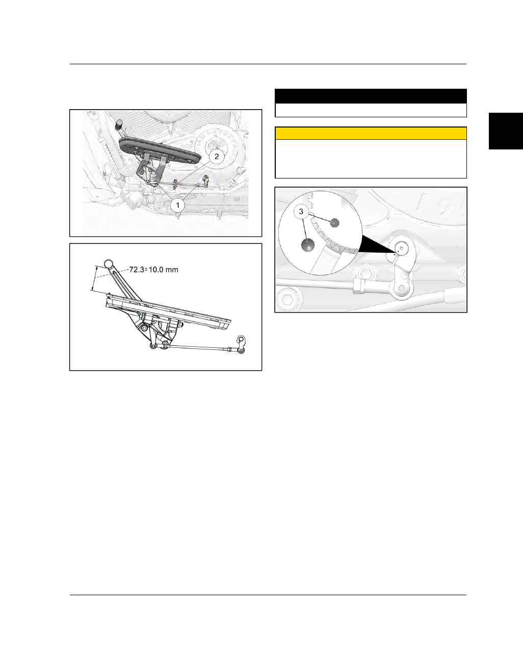
SSHHIIFFTT PPEEDDAALL AADDJJUUSSTTM

MEENNTT

1.

Loosen jam nuts

q

.

2.

Rotate linkage rod

w

until pedal angle is correct.

3.

Tighten jam nuts

q

to specification.

TORQUE

Shift Rod Jam Nuts:

84 in-lbs (10 Nm)

CAUTION

Do not remove and reposition the shift arm on the

shift shaft to adjust gear shift pedal height. Dots on

shift shaft and shift arm must be aligned for gears to

shift correctly.

MAINTENANCE

2.18

9927618 R03 - 2017 Indian Motorcycle (Full-Size) Service Manual

BBRRAAKKEE FFLLUUIIDD LLEEVVEELL IINNSSPPEECCTTIIOONN

IMPORTANT

The brake fluid level in the reservoir will go down as

brake pads wear. If you notice a constant or sudden

lowering of the brake fluid level, inspect brake pads

for wear and brake system for leaks.

Front Brake Fluid Inspection

1.

Turn handlebars or adjust the motorcycle until top
of reservoir is level.

2.

View front brake fluid level through sight glass.
The fluid should be clear and at or above the LOW
level mark

q

.

3.

Wipe area around reservoir cover with a clean
cloth.

4.

Wipe brake fluid container with a clean cloth.

5.

Remove fasteners

w

, reservoir cover

e

and

diaphragm

r

. If diaphragm is extended, return it

to the neutral position.

6.

Carefully add enough DOT 4 brake fluid to bring
level to the upper edge of the sight glass.

7.

Reinstall reservoir diaphragm and cover and
torque fasteners to specification.

TORQUE

Front Master Cylinder Cover Fasteners:

14 in-lbs (2

Nm)

Rear Brake Fluid Inspection

8.

Fluid level is checked at the rear brake master
cylinder reservoir.

9.

View fluid level through reservoir sight glass

t

.

The fluid should be clear and at a level between
UPPER and LOWER level marks.

10. Wipe area around reservoir cover with a clean

cloth.

11. Wipe brake fluid container with a clean cloth.

12. Remove fasteners

y

, reservoir cover

u

, and

diaphragm

i

. If diaphragm is extended, return it

to the neutral position.

13. Carefully add enough DOT 4 brake fluid to bring

level to the upper edge of the sight glass.

MAINTENANCE

2

2.19

14. Install

diaphragm

and

cover.

Tighten

cover

fasteners to specification.

TORQUE

Rear Master Cylinder Cover Fasteners:

7 in-lbs (1

Nm)

FFRROONNTT BBRRAAKKEE PPAADD IINNSSPPEECCTTIIOONN

NOTE

Wear indicator grooves are provided on each front

brake pad to allow for a visual inspection without pad

removal. Inspect pads by viewing from rear of

caliper.

Replace pads if worn to bottom of grooves. See Front

Brake Pad Replacement, page 9.26

1. Remove two acorn nuts

q

and fastener

w

from

each side of the motorcycle and remove the caliper
covers

e

.

2. Viewing the front brake pads from the rear of the

calipers, locate the wear indicator grooves

q

.

3. Wear indicator grooves should be visible on both

inboard and outboard brake pads of both calipers.

CAUTION

Front brake pads should always be replaced as a

complete set. If it is determined that an individual

brake pad has worn past the wear indicator groove,

both front calipers should receive new pad sets.

Failure to replace both sets of front brake pads

together may cause reduced braking performance or

brake failure, resulting in a vehicle crash.

4. Install caliper cover. Torque to specification.

TORQUE

Caliper Cover Acorn Nuts:

18 in-lbs (2 Nm)

MAINTENANCE

2.20

9927618 R03 - 2017 Indian Motorcycle (Full-Size) Service Manual

RREEAARR BBRRAAKKEE PPAADD IINNSSPPEECCTTIIOONN

NOTE

Wear indicator grooves are provided on each rear

brake pad to allow for a visual inspection without pad
removal. Inspect pads by viewing from the rear of the

motorcycle, directly behind the LH tailpipe.

Replace pads if worn to bottom of grooves. See Rear

Brake Pad Replacement, page 9.27.

1.

Place the motorcycle in an upright position with
the front wheel clamped in a wheel vise.

2.

Viewing the rear brake pads from behind the
motorcycle and below the lip of the rear fender,
locate the wear indicator grooves

q

.

3.

Wear indicator grooves should be visible on both
inboard and outboard brake pads.

CCRRAANNKKCCAASSEE VVEENNTTIILLAATTIIOONN SSYYSSTTEEM

M

1.

Inspect condition of ventilation hose

q

along its

length and at both ends.

2.

Inspect condition of ventilation hose

w

along its

length and at both ends.

3.

Be sure hoses are not restricted, kinked, or
cracked.

4.

Replace hose if worn or damaged.

MAINTENANCE

2

2.21

FFUUEELL TTAANNKK VVEENNTT IINNSSPPEECCTTIIOONN ((4499 SSTTAATTEE))

1.

Inspect fuel tank vent hose

q

in accordance with

periodic maintenance schedule and any time fuel
tank has been removed and installed. Be sure the
hose is clear and not pinched or kinked, and that
all connections are tight.

EEVVAAPPOORRAATTIIVVEE EEM

MIISSSSIIOONN CCOONNTTRROOLL SSYYSSTTEEM

M

((CCAALLIIFFOORRNNIIAA AANNDD IINNTTEERRNNAATTIIOONNAALL M

MOODDEELLSS))

NOTE

The fuel tank vent line is routed to a vapor canister

where the fuel vapor is stored until specific operating

parameters are met and the ECM opens the purge

valve. Fuel vapor is then routed out of the vapor

canister, through the purge valve and into the throttle

body for combustion. Inspect all EVAP lines for

abrasion or wear. Check that all connections for both

vent and canister purge systems are securely

attached.

NUMBER

PART DESCRIPTION

q

Fuel Tank Vent Hose

w

Evaporative Emissions Vapor
Canister

e

Purge Hose (Canister to Purge
Valve)

r

Canister Purge Valve

t

Purge Hose (Purge Valve to
Throttle Body)

MAINTENANCE

2.22

9927618 R03 - 2017 Indian Motorcycle (Full-Size) Service Manual

FFUUEELL SSUUPPPPLLYY HHOOSSEE ((FFUUEELL RRAAIILL)) IINNSSPPEECCTTIIOONN

1.

The fuel supply hose (fuel rail) can be found
behind the horn cover on the RH side of the
motorcycle.

2.

Inspect fuel supply line

q

and fuel rail

w

for

deterioration, damage, leakage, or kinked areas.
Inspect fuel supply line-to-fuel rail connection

e

for signs of leakage.

3.

Replace any components that fail inspection with
genuine Indian Motorcycle replacement parts.

WARNING

The fuel lines exiting fuel pump are subjected to high

pressure. Replace with genuine Indian Motorcycle

replacement parts to reduce the possibility of fuel

line failure. Be sure fuel lines are routed properly and

do not come in contact with sharp or hot objects, or

anything that may cause wear or damage.

MAINTENANCE

2

2.23

SSPPAARRKK PPLLUUGG RREEM

MOOVVAALL

CAUTION

HOT COMPONENTS

Wear insulated gloves and/or allow engine and

exhaust to cool before handling these parts.

NOTE

The front spark plug can be removed without having

to remove the fuel tank by using a 3” extension and

standard 5/8” spark plug socket.

1.

With the engine at room temperature, grasp the
spark plug boot

q

and rotate back and forth

slightly to release from the spark plug. DO NOT
pull on the wire or spark plug wire may be
damaged.

2.

Grabbing only the base of the spark plug boot,
pull straight out of spark plug well.

3.

Clean out spark plug wells with compressed air to
remove any loose dirt or debris.

4.

Using a 3” extension and a 5/8” spark plug socket,
remove spark plugs.

SSPPAARRKK PPLLUUGG IINNSSPPEECCTTIIOONN // GGAAPP

CAUTION

A hot engine can cause serious burns. Allow engine

to cool or wear protective gloves when removing the

spark plugs.

1.

Remove spark plugs. See Spark Plug Removal,
page 2.23.

2.

Inspect electrodes for wear and carbon buildup.
Look for a sharp outer edge with no rounding or
erosion of the electrodes.

3.

Clean with electrical contact cleaner or a glass
bead spark plug cleaner only.

CAUTION

A wire brush or coated abrasive (sandpaper) should

not be used to clean electrodes.

4.

Measure electrode gap with a wire gauge

q

.

Adjust gap if necessary by carefully bending the
grounding electrode until the specified gap is
achieved.

Spark Plug Type:

DCPR8E

Spark Plug Gap:

.034 in (0.9 mm)

MAINTENANCE

2.24

9927618 R03 - 2017 Indian Motorcycle (Full-Size) Service Manual

SSPPAARRKK PPLLUUGG IINNSSTTAALLLLAATTIIOONN

1.

Inspect spark plug gap with a wire gauge. If gap
adjustment is necessary, bend ground electrode
carefully using a spark plug gap tool.

Spark Plug Type:

DCPR8E

Spark Plug Gap:

.034 in (0.9 mm)

2.

Apply anti-seize compound sparingly to spark
plug threads, avoiding the bottom 2 - 3 threads.

3.

Torque spark plugs to specification.

TORQUE

Spark Plug:

13 ft-lbs (17 Nm)

CAUTION

Do not over tighten spark plugs. Damage to the

cylinder head or spark plug may result.

4.

Install spark plug wire boots securely over the
plugs.

EENNGGIINNEE CCOOM

MPPRREESSSSIIOONN TTEESSTT

1. Warm engine to operating temperature.

2. Shift transmission into neutral and stop engine.

3. Remove the LH upper side cover to access the fuse

box

q

. See Side Cover (Upper), Removal /

Installation, page 7.17.

4. Remove the Fuel Pump Relay

w

to disable fuel

pump.

5. Disconnect the ignition coil

e

to disable ignition

system.

6. Disconnect ignition cables from both spark plugs.

7. Remove spark plug from cylinder to be tested. See

Spark Plug Removal, page 2.23.

8. Install compression tester in the spark plug hole

following manufacturers instructions.

9. Open throttle and crank engine until needle on

compression gauge stops rising (about 5 seconds).

10. Repeat procedure for other cylinder.
Specification - Thunder Stroke 111: All Models

STD: 90-110 psi (620-758 kPa)

SERVICE LIMIT: Below 80 psi (552 kPa)

High engine compression may indicate:

• Carbon deposits in combustion chamber
• Engine modification
• Faulty Gauge

Low engine compression may indicate:

• Slow starter motor cranking speed
• Carbon or foreign material on valve seat

MAINTENANCE

2

2.25

• Worn or damaged piston and/or piston rings
• Leaking exhaust or intake valves
• Leaking head gasket
• Valve timing incorrect
• Non-OEM camshafts or faulty gauge

If

cylinder

compression

is

below

specification,

perform a cylinder leakage test to determine where
the leak is occurring. Follow the instructions provided
with the leakdown tester.

EENNGGIINNEE CCOOM

MPPRREESSSSIIOONN TTEESSTT ((W

WEETT))

If a cylinder leakage tester is not available, perform a
wet cylinder compression test.

1.

Pour 3-5 cc of clean engine oil into each cylinder
through

spark

plug

hole.

Repeat

cylinder

compression test. See Engine Compression Test,
page 2.24.

2.

If compression increases substantially, inspect
cylinder, piston, and rings.

3.

If compression does not increase, inspect valves
and valve seats.

BBAATTTTEERRYY

This motorcycle is equipped with a maintenance free
battery which is located under the seat. DO NOT
remove cell caps or add distilled water to the battery.
If the battery discharges, refer to Electrical chapter for
diagnostic information.

WARNING

Battery electrolyte is poisonous. It contains sulfuric

acid. Serious burns can result from contact with skin,

eyes or clothing. Antidote:

External:

Flush with water.

Internal:

Drink large quantities of water or milk.

Follow with milk of magnesia, beaten egg, or

vegetable oil. Call physician immediately.

Eyes:

Flush with water for 15 minutes and get prompt

medical attention.

Batteries produce explosive gases. Keep sparks,

flame, cigarettes, etc. away. Ventilate when charging

or using in an enclosed space. Always shield eyes

when working near batteries.

KEEP CHILDREN

AWAY FROM BATTERY.

CAUTION

Whenever removing the battery, disconnect the

negative (black) cable first. When reinstalling the

battery, connect the negative (black) cable last.

Do not remove the battery cables while the engine is

running. Doing so may damage the Electronic

Control Module (ECM).

Take great care NOT to reverse the battery leads

when installing the battery.

MAINTENANCE

2.26

9927618 R03 - 2017 Indian Motorcycle (Full-Size) Service Manual

BBAATTTTEERRYY IINNSSPPEECCTTIIOONN

Battery terminals and connections should be kept free
of corrosion. If cleaning is necessary, remove the
corrosion with a stiff wire brush. Wash with a solution
of one tablespoon baking soda to one cup water. Rinse
well with tap water and dry off with clean rags. Coat
terminals with dielectric grease.

1.

Visually inspect the exterior of the battery.
Replace battery if housing is damaged, case is
deformed, or if electrolyte is leaking.

2.

To

remove

corrosion,

remove

battery

from

motorcycle and wash terminals with water and
baking soda solution. Clean terminals, fasteners,
and cable ends with a brass wire brush and apply
a thin film of dielectric grease.

3.

Measure battery voltage.

Specification: 12.5V DC minimum

4.

If battery voltage is below 12.5V DC, charge it
thoroughly. See Battery Charging - In Service,
page 10.16.

5.

Replace battery if it will not accept a charge.

BBAATTTTEERRYY CCHHAARRGGIINNGG

See Battery Charging - New Battery, page 10.15 or
Battery Charging - In Service, page 10.16.

BBAATTTTEERRYY SSTTOORRAAGGEE

When the motorcycle is not used for periods of one
month or longer the battery should be fully charged
prior to operation. Store battery in a cool, dry place.

Battery should be charged monthly using a 12 volt
battery charger with a maximum charge rate of 1.8
amp-hr.

WARNING

Battery charging can create explosive gasses;

keep sparks, flames, cigarettes or anything that

could ignite the gasses away. Provide adequate

ventilation when charging in an enclosed space.

Batteries contain acid that is caustic. Wear

protective clothing and a face shield or protective

eyewear when working with the battery. KEEP

OUT OF REACH OF CHILDREN.

BBAATTTTEERRYY RREEM

MOOVVAALL

IMPORTANT

It is not necessary to disconnect the VCM from

the electrical harness during battery removal. If

the VCM must be disconnected for any reason,

the negative battery cable must be disconnected

first.

1.

Remove the upper side covers. See Side Cover
(Upper), Removal / Installation, page 7.17.

2.

Remove the seat. See Seat Removal / Installation -
All (except Roadmaster), page 7.21.

3.

Remove the fastener securing the Vehicle Control
Module (VCM) mounting plate to the top of the
battery box and move the VCM out of the way.

Do

not disconnect VCM

. See Vehicle Control Module

(VCM), Removal / Installation, page 10.48.

4.

Remove negative (-) battery terminal fastener and
cable first

q

.

5.

Remove positive (+) battery terminal fastener and
cable last

w

.

MAINTENANCE

2

2.27

6.

Lift battery straight up and out of the battery box.

NOTE

It may be necessary to push the VCM harness away

from the battery, into the RH side of the frame in

order to remove the battery.

BBAATTTTEERRYY IINNSSTTAALLLLAATTIIOONN

1.

See Battery Installation, page 10.13.

DDRRIIVVEE BBEELLTT IINNSSPPEECCTTIIOONN

NOTE

Inspect drive belt in accordance with Periodic

Maintenance Interval Chart and replace at specified

intervals regardless of belt condition. See Periodic

Maintenance Interval Table, page 2.6.

DRIVE BELT

WEAR

EXAMPLES

CONDITION

SERVICE

RECOMMEN-

DATION

External Tooth
Cracks

Replace Belt

Internal Tooth
Cracks

OK to run, but
monitor
condition

Fuzzy Edge
Cord

OK to run, but
monitor
condition

Hook Wear

Replace Belt

Missing Teeth

Replace Belt

Bevel Wear
(Outer Edge
Only)

OK to run, but
monitor
condition

Chipping (Not
Serious)

OK to run, but
monitor
condition

Stone Damage

Belt should be
replaced if
damage is on
the edge of the
belt

1.

Periodically inspect drive belt for cuts, excessive
wear, foreign substance (oil, grit), missing teeth,
or any other damage.

2.

If any damage is found, belt should be replaced.

NOTE

Adjust drive belt tension at intervals in accordance

with the Periodic Maintenance Interval Chart. See

Periodic Maintenance Interval Table, page 2.6.

3.

If the drive belt or sprocket is being replaced due
to damage, replace belt and both sprockets as a
set if drive system has more than 5000 miles (8000
Km) of use.

MAINTENANCE

2.28

9927618 R03 - 2017 Indian Motorcycle (Full-Size) Service Manual

DDRRIIVVEE BBEELLTT SSPPEECCIIFFIICCAATTIIOONNSS

DDRRIIVVEE BBEELLTT DDEEFFLLEECCTTIIOONN DDAATTAA

MODEL

DEFLECTION AT 10 LBS FORCE

Chief
Classic

1.1” (28 mm)

or

8 notches up on belt

guard. See Drive Belt Tension, page 2.29.

Chief
Vintage

Chief
Dark
Horse

Spring-
field

1.3“ (34 mm)

or

11 notches up on belt

guard. See Drive Belt Tension, page 2.29.

Chief-
tain
Dark
Horse

Chief-
tain

Road-
master

Road-
master
Classic

DDRRIIVVEE BBEELLTT FFRREEQQUUEENNCCYY TTEENNSSIIOONN DDAATTAA

NOTE

Due to the low frequency levels produced by Indian

Motorcycle drive belts, it is recommended to use a

commercially available CLAVIS optical sensor or

equivalent to achieve the most accurate tension

measurement.

MAINTENANCE

2

2.29

DDRRIIVVEE BBEELLTT TTEENNSSIIOONN M

MEEAASSUURREEM

MEENNTT

Special Tool:

Belt Tension Gauge PV-43532

IMPORTANT

Do not adjust the belt when wet, or immediately after

riding. Belt must be

dry

and the drive system must be

at ambient temperature (60-80° F). This is extremely

important for accuracy.

IMPORTANT

Perform this procedure to achieve proper belt

tension

and

alignment. Belt tension should be set

before performing the alignment procedure.

WARNING

A drive belt that is not properly tensioned can cause

drive line noise and damage the drive belt, causing

possible belt failure and loss of control of the

motorcycle.

WARNING

Care should be taken to be sure the motorcycle will
not tip or fall while elevated. Severe personal injury

or death may occur if the motorcycle tips or falls.

1.

Secure motorcycle in an upright position with the
front wheel clamped in a wheel vise.

2.

Shift transmission into NEUTRAL.

3.

ELEVATE

rear

wheel

off

the

ground

when

checking deflection or adjusting the belt.

Find Tight Spot In Belt

4.

Use the tire valve stem as a reference and perform
the following Steps:

• Check / record belt deflection at 4 different points,

90 degrees apart. Rotate wheel in a CLOCKWISE
rotation as viewed from belt side of motorcycle.

• Place a mark on rear wheel at the tightest point

(least deflection) to use as a reference.

• Continue to rotate the wheel in normal drive

direction (CLOCKWISE) 1-2 revolutions until your
reference mark (the tightest point) is lined up with
the tension setting window in the lower belt guard

q

.

• Adjust belt deflection with wheel in this position.

5.

Place tape measure or ruler next to drive belt or
use the graduations on lower belt guard for
reference.

6.

Slide O-ring on belt tension gauge to the 10 lb.
mark.

• Place belt tension gauge squarely against belt at

center and keep it at a 90° angle to the belt surface.

7.

Push up on gauge until O-ring just touches tool
body. See Drive Belt Specifications, page 2.28 for
drive belt deflection specifications.

MAINTENANCE

2.30

9927618 R03 - 2017 Indian Motorcycle (Full-Size) Service Manual

8.

If belt deflects more than the specified distance
with 10 lbs. of force, tighten the belt. If deflection
is less than specified loosen the belt. See Drive
Belt Adjustment, page 2.31.

NOTE

New drive systems (new vehicle or when belt and

sprockets are replaced) should be set to the tight

side of the specification and inspected after the first

500 miles (800 km).

DDRRIIVVEE BBEELLTT TTEENNSSIIOONN -- SSPPEECCIIFFIICCAATTIIOONNSS

Specifications: Drive Belt

BELT DEFLECTION

Model

Deflection @ 10 lbs force

Chief / Chief
Darkhorse / Vintage

1.1” (28 mm)

Springfield /
Chieftain / Chieftain
Darkhorse /
Roadmaster

1.3“ (34 mm)

SONIC TENSION DATA

The following data is provided for use with the Gates
507C Sonic Tension Meter or an equivalent. Follow
Steps 1-4 and the instructions included with your
sonic tension meter.

Required Data For

Sonic Tension Meter

Specification

Span

719.10mm

Belt Width

24mm

Belt Mass Constant

8.4 g/mm

Tension
Chief / Chief
Darkhorse / Vintage

23 Hz (± 1 Hz)

Tension
Springfield /
Chieftain / Chieftain
Darkhorse /
Roadmaster

18 Hz (± 1 Hz)

MAINTENANCE

2

2.31

DDRRIIVVEE BBEELLTT AADDJJUUSSTTM

MEENNTT

IMPORTANT

Perform this procedure to achieve proper belt

tension

and

alignment. Belt tension should be set

before performing the alignment procedure.

Belt Tension

WARNING

A drive belt that is not properly tensioned can

cause drive line noise and damage the drive belt,

causing possible belt failure and loss of control of

the motorcycle

.

NOTE

Marks

q

and

w

are used as a reference for initial

wheel alignment. Marks should be in roughly the

same position on both left and right sides of wheel.

1.

Place the motorcycle in an upright position with
the front wheel clamped in a wheel vise.

2.

Make note of adjuster locations

q

and

w

.

3.

Raise the rear of the motorcycle so the rear tire can
be freely rotated.

4.

Loosen

axle

nut

e

and

retighten

to

the

ADJUSTMENT

SPECIFICATION

during

the

adjustment procedure.

TORQUE

Axle Nut Torque

(ADJUSTMENT SPECIFICATION)

:

Step 1: 15 ft-lbs (20 Nm)

Step 2: 65 ft-lbs (88 Nm)

5.

Turn the RIGHT SIDE adjuster nut

r

to achieve

proper belt tension. See Drive Belt Tension
Measurement, page 2.29.

6.

When belt tension is correct, check and adjust
final wheel alignment as follows:

Belt Alignment

MAINTENANCE

2.32

9927618 R03 - 2017 Indian Motorcycle (Full-Size) Service Manual

WARNING

A drive belt that is not properly aligned can cause

drive line noise and damage the drive belt,

causing possible belt failure and loss of control of

the motorcycle

.

NOTE

To minimize change in belt tension, use LEFT SIDE

adjuster only to make final adjustments to belt

alignment.

7.

Rotate the wheel BACKWARD. Tighten LEFT SIDE
adjuster until belt comes off inside sprocket flange
during backward wheel rotation.

IMPORTANT

The belt should track to the center of the sprocket

tooth surface when properly aligned

t

. Sprocket

teeth should be visible on both sides of the drive

belt.

8.

Rotate the wheel in the FORWARD direction and
verify that sprocket teeth are still visible on both
sides of the drive belt

t

.

9.

If necessary, loosen the axle nut and LEFT SIDE
adjuster until belt just moves off the right flange
and begins to track down the center of the driven
sprocket flange during forward wheel rotation.

NOTE

It may be necessary to loosen the axle nut and tap

the left end of the axle to ensure it moves forward

when the adjuster is loosened. The axle nut must be

retightened to the ADJUSTMENT SPECIFICATION

before proceeding.

10.

Rear wheel alignment is satisfactory when the
drive belt remains centered on driven sprocket
during forward and backward wheel rotation.
Sprocket teeth should be visible from both
sides of the drive belt.

11. Verify that drive belt tension is still within

specification.

See

Drive

Belt

Tension

Measurement, page 2.29.

12. Tighten rear axle nut to FINAL specification.

TORQUE

Axle Nut Torque

(FINAL TIGHTENING)

:

Step 1: 15 ft-lbs (20 Nm)

Step 2: 65 ft-lbs (88 Nm)

13. Pump rear brake pedal several times to reset

brake pad distance.

14. Verify wheel rotates smoothly and freely without

drag when brake pedal is released.

SSPPRROOCCKKEETT IINNSSPPEECCTTIIOONN

NOTE

Drive belt and sprocket service life are maximized

and drive line noise minimized by proper cleaning.

Cleaning interval is approximately every tire change,

or more often if operated in dirty, dusty, or high

debris environments.

Inspection

1.

Clean the drive belt and front and rear sprockets
with a mild mixture of dish soap and warm water.
Rinse and dry thoroughly.

2.

Inspect front and rear sprocket teeth for wear or
damage from foreign material.

3.

Closely inspect drive belt condition.

FFUUSSEE RREEPPLLAACCEEM

MEENNTT

Fuses and relays are located in the fuse box under
the LH upper side cover.

1. Remove LH upper side cover. See Side Cover

(Upper), Removal / Installation, page 7.17.

MAINTENANCE


Content      ..     4      5      6      7     ..