Indian motorcycle 2017. Service Manual - page 21
 

  Главная      Manuals     Indian motorcycle 2017. Service Manual


Search            copyright infringement  


Content      ..     19      20      21      22     ..


Indian motorcycle 2017. Service Manual - page 21


6.36

9927618 R03 - 2017 Indian Motorcycle (Full-Size) Service Manual

LLEEFFTT CCRRAANNKKCCAASSEE AASSSSEEM

MBBLLYY

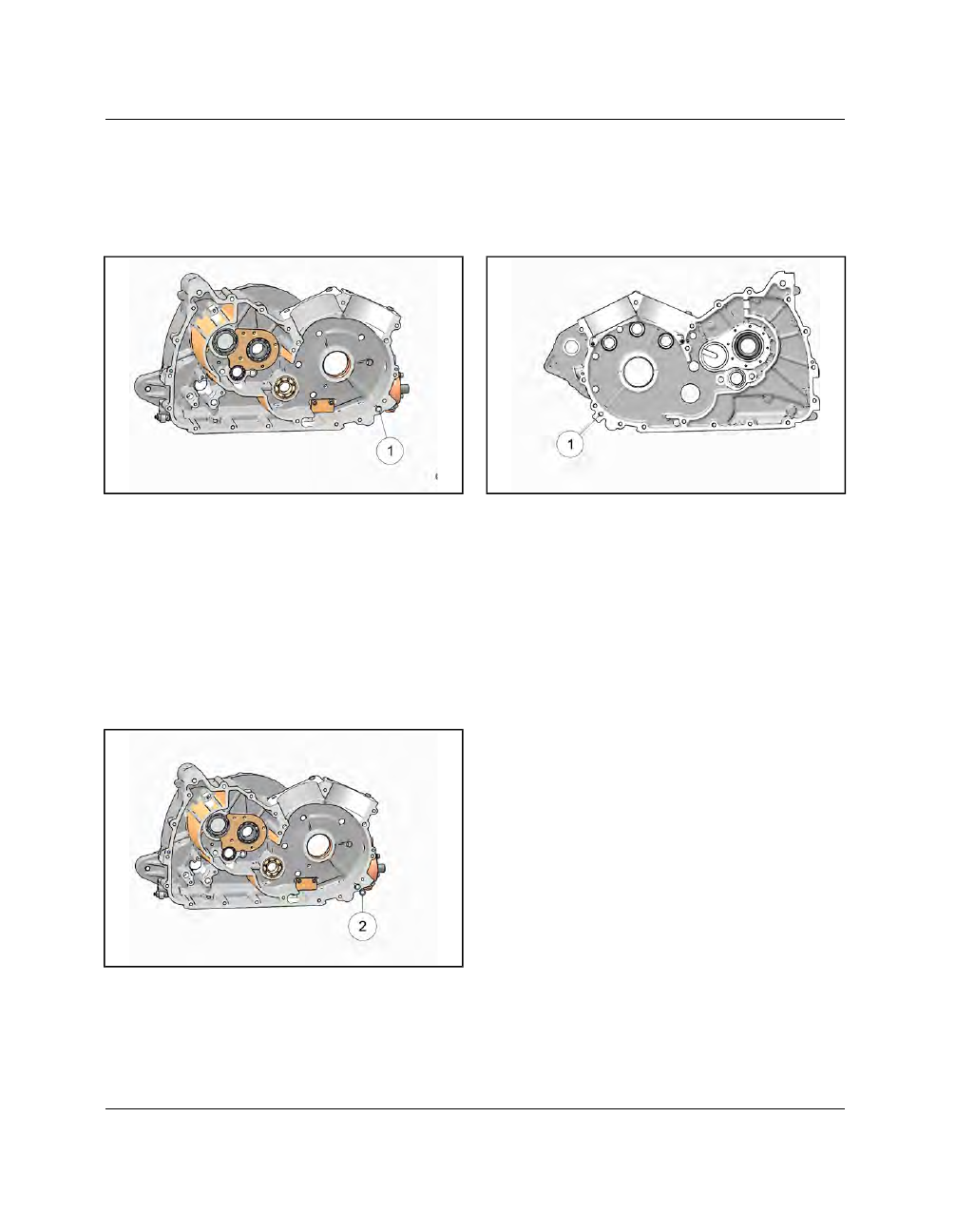
Prepare LEFT crankcase for assembly:

Refer to crankcase assembly view for locations and
torque values. See Crankcase, page 6.6.

1.

Clean crankcase and oil passage

q

thoroughly.

Rinse and dry with compressed air.

2.

Install new ball bearings in crankcase as required.

• Apply a film of lithium grease to outer race of

bearings to prevent galling upon installation

• Press on outer race of bearings using an arbor press

and a suitable arbor that is slightly smaller than
bearing outside diameter

• DO NOT press on inner race of ball bearings

3.

Install bearing retainers as required and torque to
specification.

4.

Install

scavenge

filter

screen

assembly.

See

Lubrication System, page 3.26.

5.

Install new oil passage o-ring

w

.

RRIIGGHHTT CCRRAANNKKCCAASSEE AASSSSEEM

MBBLLYY

Prepare RIGHT crankcase for assembly:

Refer to crankcase assembly view for locations and
torque specification. See Crankcase, page 6.6.

1.

Clean crankcase oil passages

q

thoroughly. Rinse

and dry with compressed air.

2.

Install new bearings in crankcase as required.

• Apply a film of lithium grease to outer race of

bearings to prevent galling upon installation.

• Press on outer race of bearings using an arbor press

and a suitable arbor that is slightly smaller than
bearing outside diameter.

• DO NOT press on inner race of ball bearings.

3.

Install bearing retainers as required and torque to
specification.

TRANSMISSION / CRANKSHAFT

6

6.37

CCRRAANNKKSSHHAAFFTT IINNSSTTAALLLLAATTIIOONN

NOTE

Install left engine case onto an engine stand.

1.

If balance shaft is already in place, rotate the
balance shaft counter weight

q

out of the way

prior to crankshaft installation.

2.

Apply assembly paste to main bearings.

3.

Hold crankshaft over left crankcase and position
rods so that left side rod is in cutout for rear
cylinder and right side rod is in cutout for the front
cylinder.

4.

Place crankshaft

w

into left crankcase half.

TRANSMISSION / CRANKSHAFT

6.38

9927618 R03 - 2017 Indian Motorcycle (Full-Size) Service Manual

TTRRAANNSSM

MIISSSSIIOONN IINNSSTTAALLLLAATTIIOONN

1.

If transmission shaft bearings were replaced, be
sure all bearing retainer plate fasteners are
installed and tightened to specification. See
Crankcase, page 6.6.

2.

Working on a flat surface, assemble the input shaft

q

and output shaft

w

so the gears are properly

meshed.

3.

Install shift rails

e

into shift forks and assemble to

input and output shafts.

4.

Lubricate parts with engine oil. Apply assembly
lube to ends of transmission shafts.

5.

Install input shaft

r

and output shaft

t

, shift forks

and rails

y

into the left crankcase. Make certain

both shafts are fully seated and rotate freely.

6.

Rotate shift rails away from shift drum bore and
install shift drum

u

.

7.

Rotate shift drum to align proper grooves with
forks.

8.

Move shift fork pins into drum grooves and seat
rails.

9.

Install balance shaft. See Balance Shaft Installation,
page 6.17.

10. Instal

oil

pump

assembly.

See

Oil

Pump

Installation, page 3.29.

11. Install crankshaft. See Crankshaft Installation,

page 6.37.

12. Assemble crankcase. See Crankcase Assembly,

page 6.39.

TRANSMISSION / CRANKSHAFT

6

6.39

CCRRAANNKKCCAASSEE AASSSSEEM

MBBLLYY

1.

Clean crankcase mating surfaces to remove all
grease, oil, and old sealant.

2.

Check to be sure all shafts are seated properly
(crankshaft, balance shaft, shift drum, shift forks,
input shaft, output shaft).

3.

Check to be sure that a new oil passage o-ring

q

,

alignment dowel pins and oil pipes, etc. are in
place.

4.

Remove the drive sprocket spacer

w

and o-ring

e

from the RH crankcase prior to installation.

5.

Place the Engine Case Splitting / Assembly tool

PF-51234

on a flat surface and assemble the M6

threaded spacers

r

and M12 threaded spacer

t

into the main plate

y

as shown.

Use only holes

marked with the letter A.

6.

Install case assembly adapter

u

, nut

i

and

washer

o

onto main plate.

TRANSMISSION / CRANKSHAFT

6.40

9927618 R03 - 2017 Indian Motorcycle (Full-Size) Service Manual

7.

Install the main plate assembly

a

to the RH

crankcase and torque fasteners to specification.

IMPORTANT

• Plate surface should be parallel to the surface of

the engine crankcase.

• All threaded spacers must be in contact with

engine case prior to fastening on the plate
assembly.

TORQUE

Main Plate Mounting Fasteners (All):

88 in-lbs (10

Nm)

8.

Apply a light even bead of Loctite

TM

Ultra Black

598 to entire case sealing surface.

9.

Spread sealant into a thin even layer on entire case
mating surface. Be sure all areas are covered. DO
NOT

ALLOW

SEALANT

TO

DRY.

CONTINUE

ASSEMBLY UNTIL CASES ARE SEALED AND ALL
FASTENERS ARE TIGHT.

10. Lower the RH case onto the LH case and install the

case installation adapter onto the transmission
output shaft.

11. Pull crankcase together by tightening nut and

tapping on crankcase with a soft mallet.

NOTE

The cases will mate before the output shaft is drawn

fully into bearing. IMPORTANT! Continue to turn nut

and tap case until sealant squeezes out along the

entire perimeter and resistance is felt when turning

nut.

12. Remove the tool.

13. Install

crankcase

fasteners

and

torque

to

specification. See Crankcase Bolt Length And
Torque Pattern, page 6.8.

14. Install a new output seal in RH crankcase using

seal installer

PF-51243

.

15. Install the o-ring and drive sprocket spacer

removed in STEP 4 with tapered edge toward the
o-ring.

16. Install the gear position switch. See Sensors —

Powertrain Management, page 4.12.

17. Install the drive sprocket. See Drive Sprocket

Installation, page 8.51.

18. Install the balance shaft driven gear and drive

gear. See Balance Shaft Installation, page 6.17.

19. Install

the

starter

drive.

See

Starter

Drive

Installation, page 6.21.

TRANSMISSION / CRANKSHAFT

6

6.41

20. Install the inner cam chain cover. See Inner Cam

Chain Cover Installation, page 6.19.

21. Install

the

camshaft

carrier

assembly.

See

Camshaft Carrier Installation, page 3.53.

22. Install the cam chain. See Cam Chain Installation,

page 3.44.

23. Install the stator. See Stator Installation, page

10.31.

24. Install the flywheel. See Flywheel Installation,

page 5.22.

25. Install the clutch assembly. See Clutch Installation,

page 5.19.

26. Install

the

torque

compensator.

See

Torque

Compensator Installation, page 5.21.

27. Install the primary cover. See Primary Cover

Installation, page 5.12.

28. Install lifters. See Lifter Installation, page 3.46.

29. Install cylinders. See Cylinder Installation, page

3.82.

30. Install

cylinder

heads.

See

Cylinder

Head

Installation, page 3.67.

31. Install engine in frame. See Engine Installation,

page 3.17.

TRANSMISSION / CRANKSHAFT

6.42

9927618 R03 - 2017 Indian Motorcycle (Full-Size) Service Manual

SSTTAAKKEE NNUUTT IINNSSTTAALLLLAATTIIOONN

• The Stake nut is located on the clutch side of the

transmission input shaft.

• It is important that they are torqued and staked

correctly for proper function

IMPORTANT

Do not reuse or reinstall any previously used stake

nut. A new stake nut needs to be installed every time

the nut is removed or loosened.

Use the following procedure to install the stake nuts
correctly:

1.

Clean threads on shaft so there is no oil or
contaminants.

2.

Thread NEW stake nut onto shaft finger tight.

3.

Torque stake nut to specification.

4.

Stake the stake nut as shown below using round
side of punch. Do not crack or tear staking lip. Do
not use a sharp chisel to stake the nut.

TRANSMISSION / CRANKSHAFT

6

6.43

TTRROOUUBBLLEESSHHOOOOTTIINNGG

PROBLEM

POSSIBLE CAUSE

PART(S) AFFECTED

REPAIR

RECOMMENDED

Transmission Will Not
Shift

Broken Shift Cam

Shift Cam

Replace shift cam

Bent Shift Forks

Shift Fork

Replace shift fork(s)

Worn Gearshift Pawl

Shift Cam

Replace shift cam

Broken Gears

Transmission Gears

Replace necessary parts

Damaged/Broken
Bearings

Transmission, Shift Cam
Bearings

Replace necessary parts

Worn Gear Shift Ratchet
Mechanism

Shifter Ratchet

Refer to Clutch / Primary
/ Shift chapter

Broken or out-of-place
spring on shift ratchet

Shift Ratchet Spring

Refer to Clutch / Primary
/ Shift chapter

Shift Detent Ratchet Stuck

Shift Ratchet

Repair as necessary

Seized Pivot Point, Bent
External Shift Linkage

External Shift Linkage

Repair as necessary

Bent or Distorted Shift
Fork Rails

Shift Fork Rails

Replace Shift Fork Rails

Debris From Broken Parts
Locking Transmission

Transmission
Components

Repair as necessary

Excessive Noise Related
to Bottom End of Engine

Worn Main Bearings

Crankshaft and/or
Crankshaft Bearings

Repair as necessary

Worn Connecting Rod
Bearings

Connecting Rod Bearings
and/or Connecting Rod
and/or Rod Bearings

Repair as necessary

Worn Connecting Rod
Small End Bushing

Connecting Rod,
Connecting Rod Bushing,
Piston Pin, Piston

Repair as necessary

Worn, seized, chipped or
broken gear teeth

Transmission Gears

Repair as necessary

Worn, seized, chipped or
broken Transmission
Bearings

Transmission Bearings

Repair as necessary

Originates from Primary
Cover

Clutch, Torque
Compensator, Flywheel,
Oil Pump Drive

Repair as necessary

Oil Pump

Oil Pump, Oil Pump Drive

Refer to Engine / Cooling
/ Exhaust chapter

Cam Drive

Cam Chain, Cam
Sprocket

Refer to Engine / Cooling
/ Exhaust chapter

TRANSMISSION / CRANKSHAFT

6.44

9927618 R03 - 2017 Indian Motorcycle (Full-Size) Service Manual

PROBLEM

POSSIBLE CAUSE

PART(S) AFFECTED

REPAIR
RECOMMENDED

Transmission Hard to Shift

Improper Clutch
Operation

Clutch

Refer to Clutch / Primary
/ Shift chapter

Incorrect Oil Viscosity

Engine oil and filter

Refer to Engine / Cooling
/ Exhaust chapter

Incorrect Clutch
Adjustment

Clutch Adjustment

Refer to Clutch / Primary
/ Shift chapter

Bent, Rubbing, Sticky,
Broken Shift Shaft

Shifter Ratchet Assembly

Refer to Clutch / Primary
/ Shift chapter

Sticking Pivot Point, Bent
External Shift Linkage

External Shift Linkage

Repair or replace
components as necessary

Bent or Distorted Shift
Forks

Shift Forks

Replace bent shift fork

Damaged Shift Drum
Grooves

Shift Drum

Replace damaged shift
drum

Shift Ratchet Bent / Stuck

Shift Ratchet

Repair as necessary

Bent or Distorted Shift
Fork Rails

Shift Fork Rails

Replace Shift Fork Rails

Transmission Jumps Out
of Gear

Broken Shift Stop Pin

Shift Stop Pin

Replace stop pin

Worn Shift Drum Pawls or
Shifter Ratchet

Shift Drum or Shift
Linkage

Replace damaged shift
drum or shifter ratchet

Broken Shift Ratchet
Spring

Shift Ratchet Spring

Replace spring

Damaged Shift Drum
Grooves

Shift Drum

Replace shift drum

Bent, Worn, Distorted
Shift Forks

Shift Forks

Replace shift forks

Bent or Distorted Shift
Fork Rails

Shift Fork Rails

Replace shift fork rails

Worn Engagement Dogs
on Transmission Gears

Transmission Gears

Replace necessary parts

TRANSMISSION / CRANKSHAFT

7

7.1

CHAPTER 7

FRAME / BODY

GENERAL INFORMATION . . . . . . . . . . . . . . . . . . . . . . . . . . . . . . . . . . . . . . . . . . . . . . . . . . . . . . . . . . . . . . . . . . . . . . . . . . . . . . . 7.3

SERVICE NOTES

. . . . . . . . . . . . . . . . . . . . . . . . . . . . . . . . . . . . . . . . . . . . . . . . . . . . . . . . . . . . . . . . . . . . . . . . . . . . . . . . . . . . . . 7.3

SPECIAL TOOLS

. . . . . . . . . . . . . . . . . . . . . . . . . . . . . . . . . . . . . . . . . . . . . . . . . . . . . . . . . . . . . . . . . . . . . . . . . . . . . . . . . . . . . . . 7.3

ASSEMBLY VIEWS. . . . . . . . . . . . . . . . . . . . . . . . . . . . . . . . . . . . . . . . . . . . . . . . . . . . . . . . . . . . . . . . . . . . . . . . . . . . . . . . . . . . . . . . 7.4

FENDERS / SEAT

. . . . . . . . . . . . . . . . . . . . . . . . . . . . . . . . . . . . . . . . . . . . . . . . . . . . . . . . . . . . . . . . . . . . . . . . . . . . . . . . . . . . . . 7.4

FENDERS / SEAT (OPEN STYLE FENDER)

. . . . . . . . . . . . . . . . . . . . . . . . . . . . . . . . . . . . . . . . . . . . . . . . . . . . . . . . . . . . . 7.5

FRAME

. . . . . . . . . . . . . . . . . . . . . . . . . . . . . . . . . . . . . . . . . . . . . . . . . . . . . . . . . . . . . . . . . . . . . . . . . . . . . . . . . . . . . . . . . . . . . . . . 7.6

FLOORBOARDS

. . . . . . . . . . . . . . . . . . . . . . . . . . . . . . . . . . . . . . . . . . . . . . . . . . . . . . . . . . . . . . . . . . . . . . . . . . . . . . . . . . . . . . . 7.7

SIDE PANELS

. . . . . . . . . . . . . . . . . . . . . . . . . . . . . . . . . . . . . . . . . . . . . . . . . . . . . . . . . . . . . . . . . . . . . . . . . . . . . . . . . . . . . . . . . . 7.8

SEAT - ALL (EXCEPT ROADMASTER)

. . . . . . . . . . . . . . . . . . . . . . . . . . . . . . . . . . . . . . . . . . . . . . . . . . . . . . . . . . . . . . . . . . 7.9

SEAT - ROADMASTER

. . . . . . . . . . . . . . . . . . . . . . . . . . . . . . . . . . . . . . . . . . . . . . . . . . . . . . . . . . . . . . . . . . . . . . . . . . . . . . . .7.10

TRUNK, ROADMASTER

. . . . . . . . . . . . . . . . . . . . . . . . . . . . . . . . . . . . . . . . . . . . . . . . . . . . . . . . . . . . . . . . . . . . . . . . . . . . . . .7.11

LOWER FAIRING, ROADMASTER

. . . . . . . . . . . . . . . . . . . . . . . . . . . . . . . . . . . . . . . . . . . . . . . . . . . . . . . . . . . . . . . . . . . . .7.12

FAIRING, CHIEFTAIN DARK HORSE

. . . . . . . . . . . . . . . . . . . . . . . . . . . . . . . . . . . . . . . . . . . . . . . . . . . . . . . . . . . . . . . . . .7.13

FAIRING, CHIEFTAIN / ROADMASTER

. . . . . . . . . . . . . . . . . . . . . . . . . . . . . . . . . . . . . . . . . . . . . . . . . . . . . . . . . . . . . . . .7.14

SADDLEBAGS, CHIEFTAIN / ROADMASTER

. . . . . . . . . . . . . . . . . . . . . . . . . . . . . . . . . . . . . . . . . . . . . . . . . . . . . . . . . .7.15

NACELLE, VINTAGE / SPRINGFIELD

. . . . . . . . . . . . . . . . . . . . . . . . . . . . . . . . . . . . . . . . . . . . . . . . . . . . . . . . . . . . . . . . .7.16

BODY / FRAME SERVICE . . . . . . . . . . . . . . . . . . . . . . . . . . . . . . . . . . . . . . . . . . . . . . . . . . . . . . . . . . . . . . . . . . . . . . . . . . . . . . .7.17

SIDE COVER (UPPER), REMOVAL / INSTALLATION

. . . . . . . . . . . . . . . . . . . . . . . . . . . . . . . . . . . . . . . . . . . . . . . . . .7.17

SIDE COVER (LOWER), REMOVAL / INSTALLATION

. . . . . . . . . . . . . . . . . . . . . . . . . . . . . . . . . . . . . . . . . . . . . . . . .7.17

PASSENGER FOOT PEG BLANKS (DARK HORSE), REMOVAL / INSTALLATION

. . . . . . . . . . . . . . . . . . . . . . .7.18

FLOORBOARD REMOVAL

. . . . . . . . . . . . . . . . . . . . . . . . . . . . . . . . . . . . . . . . . . . . . . . . . . . . . . . . . . . . . . . . . . . . . . . . . . . .7.18

FLOORBOARD INSTALLATION

. . . . . . . . . . . . . . . . . . . . . . . . . . . . . . . . . . . . . . . . . . . . . . . . . . . . . . . . . . . . . . . . . . . . . . .7.19

FOOT PEGS (PASSENGER), REMOVAL / INSTALLATION

. . . . . . . . . . . . . . . . . . . . . . . . . . . . . . . . . . . . . . . . . . . . . .7.21

SEAT REMOVAL / INSTALLATION - ALL (EXCEPT ROADMASTER)

. . . . . . . . . . . . . . . . . . . . . . . . . . . . . . . . . . . .7.21

SEAT REMOVAL / INSTALLATION - (ROADMASTER)

. . . . . . . . . . . . . . . . . . . . . . . . . . . . . . . . . . . . . . . . . . . . . . . . .7.22

SEAT REMOVAL / INSTALLATION - (DARK HORSE)

. . . . . . . . . . . . . . . . . . . . . . . . . . . . . . . . . . . . . . . . . . . . . . . . . . .7.23

HIGHWAY BAR REMOVAL

. . . . . . . . . . . . . . . . . . . . . . . . . . . . . . . . . . . . . . . . . . . . . . . . . . . . . . . . . . . . . . . . . . . . . . . . . . . .7.24

HIGHWAY BAR INSTALLATION

. . . . . . . . . . . . . . . . . . . . . . . . . . . . . . . . . . . . . . . . . . . . . . . . . . . . . . . . . . . . . . . . . . . . . . .7.24

LOWER FAIRING REMOVAL - (ROADMASTER)

. . . . . . . . . . . . . . . . . . . . . . . . . . . . . . . . . . . . . . . . . . . . . . . . . . . . . . .7.25

LOWER FAIRING INSTALLATION - (ROADMASTER)

. . . . . . . . . . . . . . . . . . . . . . . . . . . . . . . . . . . . . . . . . . . . . . . . . .7.25

FRONT FENDER REMOVAL

. . . . . . . . . . . . . . . . . . . . . . . . . . . . . . . . . . . . . . . . . . . . . . . . . . . . . . . . . . . . . . . . . . . . . . . . . . .7.26

FRONT FENDER INSTALLATION

. . . . . . . . . . . . . . . . . . . . . . . . . . . . . . . . . . . . . . . . . . . . . . . . . . . . . . . . . . . . . . . . . . . . . .7.27

FRONT FENDER REMOVAL (OPEN STYLE FENDER)

. . . . . . . . . . . . . . . . . . . . . . . . . . . . . . . . . . . . . . . . . . . . . . . . . .7.28

FRONT FENDER INSTALLATION (OPEN STYLE FENDER)

. . . . . . . . . . . . . . . . . . . . . . . . . . . . . . . . . . . . . . . . . . . . .7.28

TRUNK REMOVAL, ROADMASTER

. . . . . . . . . . . . . . . . . . . . . . . . . . . . . . . . . . . . . . . . . . . . . . . . . . . . . . . . . . . . . . . . . . . .7.29

TRUNK INSTALLATION, ROADMASTER

. . . . . . . . . . . . . . . . . . . . . . . . . . . . . . . . . . . . . . . . . . . . . . . . . . . . . . . . . . . . . . .7.30

TRUNK LOCK REPLACEMENT - ROADMASTER

. . . . . . . . . . . . . . . . . . . . . . . . . . . . . . . . . . . . . . . . . . . . . . . . . . . . . . .7.31

REAR FENDER REMOVAL

. . . . . . . . . . . . . . . . . . . . . . . . . . . . . . . . . . . . . . . . . . . . . . . . . . . . . . . . . . . . . . . . . . . . . . . . . . . .7.33

REAR FENDER INSTALLATION

. . . . . . . . . . . . . . . . . . . . . . . . . . . . . . . . . . . . . . . . . . . . . . . . . . . . . . . . . . . . . . . . . . . . . . .7.34

FRONT CASTING (MAIN FRAME), REMOVAL

. . . . . . . . . . . . . . . . . . . . . . . . . . . . . . . . . . . . . . . . . . . . . . . . . . . . . . . . .7.35

FRONT CASTING (MAIN FRAME), INSTALLATION

. . . . . . . . . . . . . . . . . . . . . . . . . . . . . . . . . . . . . . . . . . . . . . . . . . . .7.37

FRAME / BODY

7.2

9927618 R03 - 2017 Indian Motorcycle (Full-Size) Service Manual

CHIEF CLASSIC / CHIEF DARK HORSE / CHIEF VINTAGE / SPRINGFIELD

. . . . . . . . . . . . . . . . . . . . . . . . . . . . . . . .7.40

INSTRUMENT PANEL REMOVAL / INSTALLATION

. . . . . . . . . . . . . . . . . . . . . . . . . . . . . . . . . . . . . . . . . . . . . . . . . . . .7.40

NACELLE REMOVAL

. . . . . . . . . . . . . . . . . . . . . . . . . . . . . . . . . . . . . . . . . . . . . . . . . . . . . . . . . . . . . . . . . . . . . . . . . . . . . . . . .7.41

NACELLE INSTALLATION

. . . . . . . . . . . . . . . . . . . . . . . . . . . . . . . . . . . . . . . . . . . . . . . . . . . . . . . . . . . . . . . . . . . . . . . . . . . .7.43

CHIEFTAIN DARK HORSE

. . . . . . . . . . . . . . . . . . . . . . . . . . . . . . . . . . . . . . . . . . . . . . . . . . . . . . . . . . . . . . . . . . . . . . . . . . . . . . . . .7.45

OUTER FAIRING REMOVAL - (CHIEFTAIN DARK HORSE)

. . . . . . . . . . . . . . . . . . . . . . . . . . . . . . . . . . . . . . . . . . . . .7.45

INNER FAIRING REMOVAL - (CHIEFTAIN DARK HORSE)

. . . . . . . . . . . . . . . . . . . . . . . . . . . . . . . . . . . . . . . . . . . . .7.47

INNER FAIRING INSTALLATION - (CHIEFTAIN DARK HORSE)

. . . . . . . . . . . . . . . . . . . . . . . . . . . . . . . . . . . . . . . .7.48

OUTER FAIRING INSTALLATION - (CHIEFTAIN DARK HORSE)

. . . . . . . . . . . . . . . . . . . . . . . . . . . . . . . . . . . . . . . .7.49

INSTRUMENT PANEL REMOVAL / INSTALLATION - (CHIEFTAIN DARK HORSE)

. . . . . . . . . . . . . . . . . . . . . .7.50

CHIEFTAIN / ROADMASTER

. . . . . . . . . . . . . . . . . . . . . . . . . . . . . . . . . . . . . . . . . . . . . . . . . . . . . . . . . . . . . . . . . . . . . . . . . . . . . .7.51

OUTER FAIRING REMOVAL - (CHIEFTAIN / ROADMASTER)

. . . . . . . . . . . . . . . . . . . . . . . . . . . . . . . . . . . . . . . . . .7.51

INNER FAIRING REMOVAL - (CHIEFTAIN / ROADMASTER)

. . . . . . . . . . . . . . . . . . . . . . . . . . . . . . . . . . . . . . . . . . .7.53

INNER FAIRING INSTALLATION - (CHIEFTAIN / ROADMASTER)

. . . . . . . . . . . . . . . . . . . . . . . . . . . . . . . . . . . . . .7.54

OUTER FAIRING INSTALLATION - (CHIEFTAIN / ROADMASTER)

. . . . . . . . . . . . . . . . . . . . . . . . . . . . . . . . . . . . .7.55

RIDE COMMAND SYSTEM REMOVAL

. . . . . . . . . . . . . . . . . . . . . . . . . . . . . . . . . . . . . . . . . . . . . . . . . . . . . . . . . . . . . . . .7.57

RIDE COMMAND SYSTEM INSTALLATION

. . . . . . . . . . . . . . . . . . . . . . . . . . . . . . . . . . . . . . . . . . . . . . . . . . . . . . . . . . .7.58

FRAME / BODY

7

7.3

GGEENNEERRAALL IINNFFOORRM

MAATTIIOONN

SSEERRVVIICCEE NNOOTTEESS

This section covers the removal and installation of
frame and body components, assemblies and systems.
Pay close attention to assembly procedures and torque
specifications.

Cables, hoses and tie straps that have been removed
during disassembly must be replaced per factory
standards during assembly. Caution should be used
when tightening body panels. Any deformation on the
panel around the fastener is an indication that the
fastener is too tight. Do not over tighten body
components in order to avoid damage.

SSPPEECCIIAALL TTOOOOLLSS

TOOL DESCRIPTION

PART NUMBER

PV-49955

Body Panel Tool Kit

Bosch Automotive Service Solutions:

1-800-328-

6657 or https://polaris.service-solutions.com/

FRAME / BODY

7.4

9927618 R03 - 2017 Indian Motorcycle (Full-Size) Service Manual

AASSSSEEM

MBBLLYY VVIIEEW

WSS

FFEENNDDEERRSS // SSEEAATT

NUMBER

PART DESCRIPTION

TORQUE (IF APPLICABLE)

q

Passenger Seat Fastener

18 ft-lbs (24 Nm)

w

Driver Seat Fastener

18 ft-lbs (24 Nm)

e

Strut Cover Fastener

84 in-lbs (10 Nm)

r

Rear Fender Upper Fastener

84 in-lbs (10 Nm)

t

Rear Fender Lower Stud / Ball

84 in-lbs (10 Nm)

y

Fender Fastener

84 in-lbs (10 Nm)

u

Caliper Cover Acorn Nut

18 in-lbs (2 Nm)

i

Front Fender Fastener

18 ft-lbs (24 Nm)

FRAME / BODY

7

7.5

FFEENNDDEERRSS // SSEEAATT ((OOPPEENN SSTTYYLLEE FFEENNDDEERR))

NUMBER

PART DESCRIPTION

TORQUE (IF APPLICABLE)

q

Passenger Seat Fastener

18 ft-lbs (24 Nm)

w

Driver Seat Fastener

18 ft-lbs (24 Nm)

e

Strut Cover Fastener

84 in-lbs (10 Nm)

r

Rear Fender Upper Fastener

84 in-lbs (10 Nm)

t

Rear Fender Lower Stud / Ball

84 in-lbs (10 Nm)

y

Fender Fastener

84 in-lbs (10 Nm)

u

Front Fender Fastener

18 ft-lbs (24 Nm)

FRAME / BODY

7.6

9927618 R03 - 2017 Indian Motorcycle (Full-Size) Service Manual

FFRRAAM

MEE

NUMBER

PART DESCRIPTION

TORQUE (IF APPLICABLE)

q

Fastener, Down Tube (Lower)— M10 x 1.5 x 60 (QTY.4)

45 ft-lbs (60 Nm)

w

Fastener, Down Tube (Lower LH) — M10 x 1.5 x 25
(QTY.1)

45 ft-lbs (60 Nm)

e

Fastener, Down Tube (Upper) — M10 x 1.5 x 100 (QTY.2)

45 ft-lbs (60 Nm)

r

Fastener — M12 x 1.75 x 120 (QTY.3)

75 ft-lbs (102 Nm)

t

Fastener, Midcast — M12 x 1.75 x 50 (QTY.3)

75 ft-lbs (102 Nm)

y

Fastener, Rear Subframe — M10 x 1.5 x 35 (QTY.6)

35 ft-lbs (48 Nm)

u

Fastener, Rear Lower Subframe — M8 x 1.25 x 20 (QTY.4)

18 ft-lbs (24 Nm)

i

Fastener, Engine Bracket — M8 x 1.25 x 20 (QTY.2)

18 ft-lbs (24 Nm)

FRAME / BODY

7

7.7

FFLLOOOORRBBOOAARRDDSS

NUMBER

PART DESCRIPTION

TORQUE (IF APPLICABLE)

q

Fastener, Floorboard Pivot — M8 x 1.25 x 120 (QTY.2)

18 ft-lbs (24 Nm)

w

Fastener, Floorboard Support — M10 x 1.5 x 30 (QTY.4)

35 ft-lbs (48 Nm)

e

Fastener, Brake Pedal Pad — M6 x 1.0 x 15 (QTY.2)

84 in-lbs (10 Nm)

r

Shifter Toe Pedal

18 ft-lbs (24 Nm)

t

Floorboard Pan

-

y

Floorboard Pad

-

u

Brake Pedal Pad

-

i

External Snap Ring (Brake Pedal and Shifter)

-

o

Retaining Pin, Pushrod

-

a

Passenger Foot Peg Support Bracket

-

s

Passenger Foot Peg

-

FRAME / BODY


Content      ..     19      20      21      22     ..