Indian motorcycle 2017. Service Manual - page 23
7.24
9927618 R03 - 2017 Indian Motorcycle (Full-Size) Service Manual
HHIIGGHHW
WAAYY BBAARR RREEM
MOOVVAALL
Place the motorcycle on the side stand. Turn the han-
dlebar all the way to the left.
CAUTION
Protect chrome and painted surfaces prior to
removal, particularly the front fender.
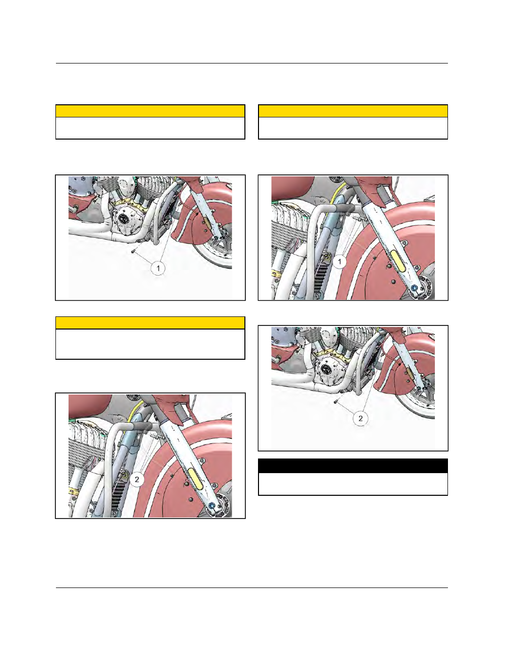
1.
Using an 8 mm hex wrench, remove the lower two
fasteners
q
from the right and left side of the
highway bar assembly.
2.
CAUTION
Hold the highway bar assembly in place while
removing the top fasteners so it doesn’t swing down
and damage the front fender.
Using a 6 mm hex wrench, remove the top two
fasteners
w
from the highway bar assembly.
3.
Carefully maneuver the highway bar out from the
frame / fender area.
HHIIGGHHW
WAAYY BBAARR IINNSSTTAALLLLAATTIIOONN
Place the motorcycle on the side stand. Turn the han-
dlebar all the way to the left.
CAUTION
Protect chrome and painted surfaces prior to
removal, particularly the front fender.
1.
Carefully maneuver the highway bar into position
and thread the upper mounting fasteners
q
in
finger tight.
2.
Install the lower mounting fasteners
w
and torque
upper and lower fasteners to specification.
TORQUE
Upper Highway Bar Fasteners:
18 ft-lbs (24 Nm)
Lower Highway Bar Fasteners:
35 ft-lbs (48 Nm)