Indian motorcycle 2017. Service Manual - page 29
 

  Главная      Manuals     Indian motorcycle 2017. Service Manual


Search            copyright infringement  


Content      ..     27      28      29      30     ..


Indian motorcycle 2017. Service Manual - page 29


8

8.61

4. Thoroughly clean the shock spring.

5. Inspect shock for signs of oil seepage around the

shaft seal. If leakage is suspected rebuild the shock
absorber assembly.

6. Inspect eyelets

e r

for cracks, damage or loose

fitting eyelet. Rebuild shock if either eyelet is
cracked.

7. Inspect damper rod for corrosion, pitting, or

damage. Rebuild shock if any of the above is
evident.

8. With shock upright, move damper rod through

entire travel range. Damper rod should move
smoothly with consistent damping through the
entire travel range, and return to the fully extended
position when released. Rebuild shock if damping
is inconsistent, or if gas leakage has occurred and
the damper rod does not fully extend when
released.

9. Inspect shock spring for cracks or distortion.

Measure free length and compare to specification.
See Service Specifications, page 8.40.

Chieftain / Chieftain Dark Horse / Roadmaster
/ Springfield

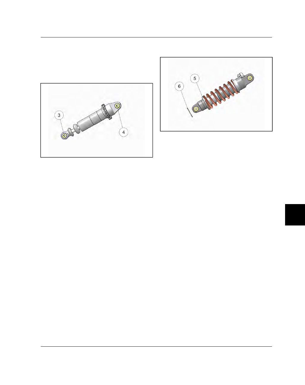
10. Install the shock / spring assembly in a suitable

spring compressor.

11. Compress spring enough to raise the lower keeper

t

and remove the circlip

y

.

12. Remove the lower keeper and slide spring off of

shock.

13. Thoroughly clean the shock spring.

14. Inspect shock for signs of oil seepage around the

shaft seal. If leakage is suspected rebuild the shock
absorber assembly.

15. Inspect eyelets for cracks or damage. Rebuild

shock if either eyelet is cracked.

16. Inspect damper rod for corrosion, pitting, or

damage. Rebuild shock if any of the above is
evident.

17. Inspect shock spring for cracks or distortion.

Measure free length and compare to specification.
See Service Specifications, page 8.40.

STEERING / SUSPENSION

8.62

9927618 R03 - 2017 Indian Motorcycle (Full-Size) Service Manual

SSHHOOCCKK AABBSSOORRBBEERR IINNSSTTAALLLLAATTIIOONN

1.

Grease all pivot points.

2.

Lift shock into position and install top shock
fastener

q

from right to left, and install nut finger

tight.

3.

Install the lower shock fastener

w

from right to

left, and install nut finger tight.

4.

Torque upper and lower shock fasteners to
specification.

TORQUE

Shock Fasteners (All Models):

55 ft-lbs (75 Nm)

5.

Install the swingarm / shock absorber assembly.
See Swingarm Installation, page 8.67.

6.

Set

suspension

ride

height

/

preload

to

accommodate rider /cargo weight. See Rear Shock
Preload Inspection, page 2.37.

STEERING / SUSPENSION

8

8.63

SSW

WIINNGGAARRM

M SSEERRVVIICCEE

SSW

WIINNGGAARRM

M RREEM

MOOVVAALL

WARNING

Swingarm removal involves supporting the machine

with the rear end elevated. Take precautions so that
the motorcycle is securely supported when the rear

tire is off the ground. Severe personal injury or death

can occur if the motorcycle tips or falls.

WARNING

Make sure the exhaust system has cooled to room

temperature before elevating the motorcycle. The

drive belt may be damaged if it comes into contact

with HOT exhaust components.

WARNING

If working on a motorcycle equipped with a charcoal

canister (EVAP), remove the canister prior to

elevating the rear of the motorcycle to prevent

damage to the canister hose fittings.

1. Place the motorcycle in an upright position on a lift

table with the front wheel clamped in a wheel vise.

2. Position a platform jack beneath the engine cases

and raise until it contacts the engine.

3. If equipped, remove the charcoal canister. See

Evaporative Emission Control System (CA Models),
page 2.21.

4. Remove saddlebags, if equipped. Refer to Owner’s

Manual.

5. Remove upper and lower side panels. See Side

Cover (Upper), Removal / Installation, page 7.17
and Side Cover (Lower), Removal / Installation,
page

.

6. Remove the seat. See Seat, Removal / Installation -

Classic / Vintage / Chieftain, page 7.21.

7. Remove rear wheel assembly. See Rear Wheel

Removal / Installation, page 8.56.

8. Remove the rear brake hose rear p-clamp

q

and

front p-clamp

w

fasteners located on the left inner

surface of the swingarm.

9. Remove the rear ABS wheel speed sensor harness

p-clamp fastener

e

from the front left side of the

swingarm.

10. Disconnect the rear ABS wheel speed sensor

connector located at the front of swingarm.

11. Remove the plastic darts

r

securing the rear wheel

debris flap

t

to the forward upper edge of the rear

fender.

12. Disconnect the tip over sensor connector

y

located on the rear wheel debris flap and remove
debris flap

t

.

STEERING / SUSPENSION

8.64

9927618 R03 - 2017 Indian Motorcycle (Full-Size) Service Manual

13. Remove swingarm nut

u

and outer pivot spacer

i

from the left side of the swingarm pivot shaft.

14. Remove the pivot jamb nut

o

located on the right

side of the swingarm pivot shaft.

15. Use an 8 mm hex wrench to thread the swingarm

shaft

a

out of the right side of the frame.

16.

CHIEFTAIN / CHIEFTAIN DARK HORSE /
ROADMASTER

/

SPRINGFIELD

ONLY:

Disconnect the shock absorber air line fitting from
the left frame section.

17. Support and remove the swingarm assembly

towards the rear of the motorcycle.

STEERING / SUSPENSION

8

8.65

SSW

WIINNGGAARRM

M BBUUSSHHIINNGG // BBEEAARRIINNGG RREEPPLLAACCEEM

MEENNTT

NOTE

Disassembly and assembly of the swingarm requires

Swingarm Bushing Tool

(PF-51237)

.

REMOVAL

1.

Remove swingarm assembly from motorcycle. See
Swingarm Removal, page 8.63.

2.

Remove shock absorber assembly from swingarm.
See Shock Absorber Removal, page 8.60.

3.

Remove the two fasteners

q

and lower belt guard

w

.

4.

Remove the pivot spacer

e

from the LH side of the

swingarm followed by internal snap-ring

r

.

5.

Working from the RH side of the swingarm, gently
pry the seal

t

out of the bearing bore.

6.

Assemble the Swingarm Bushing Tool

(PF-51237)

:

1. Thread

nut

y

on

to

threaded

rod

u

approximately 1/2 way.

2. Slide bearing

i

on to threaded rod followed

by washer

o

and arbor

a

.

3. Drop spreader ball

s

into adapter

d

and

thread rod into adapter until the end lightly
contacts the spreader ball.

STEERING / SUSPENSION

8.66

9927618 R03 - 2017 Indian Motorcycle (Full-Size) Service Manual

7.

Lay the press plate

f

over the needle bearing and

install the Swingarm Bushing Tool

(PF-51237)

through the needle bearing as shown.

8.

Raise the arbor up high enough to hold the
adapter in place with an open ended wrench.

9.

Turn the top of the threaded rod in until the
adapter fingers are spread enough to grab the
inner diameter of the needle bearing.

10. Lower the arbor until its seated on the press plate

and thread the nut down onto the bearing.

11. Hold the threaded rod in place and turn the nut in

until the needle bearing is drawn from the bore.

12. With the needle bearing removed, gently pry the

inner seal

g

out of the needle bearing bore.

13. Insert a suitable bearing driver or drift through the

RH side of the swingarm and drive the two
bearings

h

out through the LH side.

14. Inspect bearing bores for any galling or damage.

STEERING / SUSPENSION

8

8.67

INSTALLATION

15. Working on the LH side of the swingarm, press or

drive

new

bearings into the bearing bore using a

suitable bearing driver.

16. Install internal snap-ring and spacer removed in

STEP 4 of this procedure.

17. Working on the RH side of the swingarm, press a

new

inner

seal into the bearing bore until seated

on the shoulder.

18. Using the bearing driver

j

provided in Swingarm

Bushing Tool

(PF-51237)

, drive a new needle

bearing into the RH side of the swingarm until fully
seated.

19. Press a new

outer

seal into the bearing bore until

seated.

20. Install lower belt guard and torque fasteners to

specification.

TORQUE

Lower Belt Guard Fasteners:

96 in-lbs (11 Nm)

21. Install

shock

absorber assembly.

See

Shock

Absorber Installation, page 8.62.

22. Install

swingarm

assembly.

See

Swingarm

Installation, page 8.67.

SSW

WIINNGGAARRM

M IINNSSTTAALLLLAATTIIOONN

Drive belt must be installed on the drive sprocket
prior to installing the swingarm.

1. Clean inside of the swingarm shaft bores in both

sides of the frame midcastings.

2. Grease swingarm pivot shaft.

3. If previously removed, install the shock absorber

and

pushrod

assembly.

See

Shock

Absorber

Installation, page 8.62.

4. Apply a thin film of grease to the LH swingarm

spacer

q

and press into position in the LH bearing

bore.

NOTE

Grease should be applied to the left side spacer so it

stays in position when swingarm is installed.

5. Lift the swingarm / shock absorber assembly into

position in the frame. Make sure the LH spacer
stays in position.

6.

CHIEFTAIN / CHIEFTAIN DARK HORSE /
ROADMASTER / SPRINGFIELD ONLY:

Install the shock absorber air line into the LH frame
section and torque nut to specification.

TORQUE

Air Line Jamb Nut:

20 ft-lbs (27 Nm)

STEERING / SUSPENSION

8.68

9927618 R03 - 2017 Indian Motorcycle (Full-Size) Service Manual

7. Use an 8 mm hex wrench to thread the swingarm

shaft

w

into the right side of the frame and torque

to specification..

TORQUE

Swingarm Shaft:

8 ft-lbs (11 Nm)

8. Install the swingarm shaft jamb nut

e

onto the end

of the swingarm shaft on the RH side. Torque jamb
nut to specification.

TORQUE

Swingarm Shaft Jam Nut:

89 in-lbs (10 Nm)

9. Working on the LH side of the motorcycle, install

the outer pivot spacer

r

and swingarm nut

t

and

torque to specification.

NOTE

The swingarm nut cannot be reused once

removed from the swingarm shaft. Apply AP
grease to the shoulder of the

new

nut prior to

installation.

TORQUE

Swingarm Nut:

65 ft-lbs (88 Nm)

10. Install the debris flap

y

and three plastic dart clips

u

and reconnect the tip over sensor

i

.

11. Connect the ABS wheel speed sensor located at the

front of the swingarm.

12. Route the ABS wheel speed sensor harness as

shown and install the p-clamp fastener

o

. Torque

to specification.

STEERING / SUSPENSION

8

8.69

13. Route the rear brake line as shown and install the

front p-clamp

a

and rear p-clamp

s

. Torque

fasteners to specification.

TORQUE

P-Clamp Fasteners:

84 in-lbs (10 Nm)

14. Install the rear wheel. See Rear Wheel Removal /

Installation, page 8.56.

15. Make sure that the following applies:

• The rear wheel turns freely, without any interference

between the belt guard, the tire, and the swingarm.

• Brake line is properly routed and secured.
• The left and right axle adjusters are aligned

properly (wheel is in alignment).

• The rear brake functions properly.
• All fasteners have been tightened correctly.
• There is adequate clearance between swingarm and

exhaust mufflers and mounting.

• The swingarm is not loose, it doesn’t wobble from

side to side, and it doesn’t move up and down more
than 1/32 of an inch when pushed and pulled firmly.

16. Install the seat.

17. Install the upper and lower side panels. See Side

Cover (Upper), Removal / Installation, page 7.17.

18. Install saddlebags, if equipped. Refer to Owner’s

Manual.

19. If equipped, install the charcoal canister. See

Evaporative Emission Control System (CA Models),
page 2.21.

20. Test ride motorcycle to be sure rear suspension

operates smoothly without binding or abnormal
noises.

21. Adjust ride height. See Rear Shock Preload

Inspection, page 2.37.

STEERING / SUSPENSION

8.70

9927618 R03 - 2017 Indian Motorcycle (Full-Size) Service Manual

TTRROOUUBBLLEESSHHOOOOTTIINNGG

TTRROOUUBBLLEESSHHOOOOTTIINNGG,, RREEAARR W

WHHEEEELL // SSUUSSPPEENNSSIIOONN

PROBLEM

POSSIBLE CAUSE

REPAIR RECOMMENDED

Rear Wheel Feels “Loose”
or Wobbles

Loose fasteners

Torque to specification

Distorted (bent) rear wheel

Replace wheel

Worn or damaged wheel bearings

Replace wheel bearings

Worn or damaged swing arm
bushings.

Replace swing arm bushings

Damaged or incorrect rear tire

Replace rear tire

Unbalanced rear wheel assembly

Balance tire/wheel

Low tire pressure

Inflate to specification

Loose swing arm, axle or suspension
fasteners

Torque to specification

Pushrod or shock bearing failure

Replace pushrod or shock bearings

Rear Suspension Too Hard

Incorrect preload adjustment

Adjust to rider & load

Damaged shock absorber

Replace / Rebuild shock

Damaged or corroded suspension
mount bushing

Correct as necessary

Damaged or corroded swingarm
bushings

Replace

High tire pressure

Deflate to specification

Drive belt adjustment too tight

Adjust drive belt tension

Rear Suspension Too Soft

Incorrect preload adjustment

Adjust to rider & load

Damaged shock absorber

Rebuild or replace shock

Weak shock spring

Replace shock spring

Excessive load placed on motorcycle

Reduce load weight

Low tire pressure

Inflate to specification

Rear Suspension Noisy

Loose fasteners

Torque to specification

Worn wheel bearings

Replace

Worn swing arm bushings

Replace

Damaged shock absorber

Replace as necessary

Worn pushrod or shock bearings

Replace pushrod or shock bearings

Wheel Drags (Turns Hard)

Incorrect drive belt adjustment

Adjust drive belt tension

Brake problem

Diagnose and Service

Loose fasteners

Torque to specification

Bent rear axle

Replace

Damaged wheel bearings

Replace

Tire contact with object or chassis

Determine point of contact and correct

STEERING / SUSPENSION

8

8.71

TTRROOUUBBLLEESSHHOOOOTTIINNGG,, FFIINNAALL DDRRIIVVEE

PROBLEM

POSSIBLE CAUSE

POSSIBLE REPAIR NEEDED

Belt Shows Excessive Wear
On One Side

Out-of-Alignment

Align rear wheel

Belt Squeal

Out-of-Alignment

Align rear wheel

Belt Whine / Noise

Out-of-Alignment
Belt Damage
Incorrect Belt Tension

Align rear wheel
Inspect Belt
Adjust Tension

Broken Sprocket Teeth

Foreign material damage / Loose drive
belt or sprocket

Replace parts or repair as necessary

Broken or Torn Cogs on Belt

Foreign material damage / Loose drive
belt or sprocket

Replace parts as necessary

Belt Jumps Sprocket Teeth

Worn, damaged or out of adjustment
belt or sprockets

Replace parts as necessary

Belt Loose

Adjust Belt

Excessive Wear, Binding
Suspension

Belt Tight

Adjust Belt

Broken Belt

Belt weakened by foreign material
damage. Belt run excessively tight or
loose.

Replace Belt, Replace Sprockets

STEERING / SUSPENSION

8.72

9927618 R03 - 2017 Indian Motorcycle (Full-Size) Service Manual

TTIIRREESS

GGEENNEERRAALL IINNFFOORRM

MAATTIIOONN

SSEERRVVIICCEE NNOOTTEESS

WARNING

If a consumer wishes to replace the Original

Equipment Manufacturer (OEM) tires with another

brand of tire, Indian Motorcycle recommends

contacting the tech-line department of the tire

manufacturer being considered to ensure

compatibility. Indian Motorcycle makes no other

recommendation other than the OEM tires. Tires

other than OEM may or may not adversely affect the

handling characteristics of the motorcycle or may not

have adequate clearance between tire and various

parts of the motorcycle.

WARNING

Indian Motorcycles are produced using the

designated tires listed as original equipment. This

includes field testing to ensure stability and superior

handling. The use of tires other than original

equipment may cause instability which can lead to a

crash resulting in serious injury or death. Use

only

the recommended tires inflated to the recommended

tire pressures. Operating the motorcycle with

damaged rims creates a safety hazard including air

pressure loss, steering imbalance and/or reduced

steering control. Do not attempt to repair or

straighten damaged rims.

WARNING

Do not attempt to repair tires that have:

• Punctures with a diameter of greater than 6mm

(0.240").

• Cuts with a length of greater than 6mm (0.240").
• Any punctures or cuts on the sidewall of the tire.
• Tread depth of less than 1.6mm (.063") for the front

tire.

• Tread depth of less than 1.6mm (.063") for the rear

tire.

• Ply separation.
• Tread separation.
• Severe tread cupping.
• Cuts, gouges or scratches on the sealing surface of

the bead.

• Flat spots on the tread.
• Bubbles, separation or any unusual damage to the

inner liner of the tire.

• Chemical sealants or balance additives added to

the tire.

WARNING

All repairs must be made from inside the tire.

WARNING

No form of temporary repair should ever be

attempted. Secondary damage caused by a

penetrating object may not be detected and tire or

tube deflation may occur at a later date.

WARNING

It is dangerous to ride with a worn tire. When a

tire reaches the minimum tread depth listed

below, replace the tire immediately.

CAUTION

Two of the biggest factors contributing to premature

tire wear are overloading and under-inflation. Do not

deviate from the specifications for loading or

inflation.

SSPPEECCIIAALL TTOOOOLLSS

TOOL DESCRIPTION

PART NUMBER

TPMS Activation Tool

PF-51288

Tire Changing Machine

Commercially Available

STEERING / SUSPENSION

8

8.73

SSEERRVVIICCEE SSPPEECCIIFFIICCAATTIIOONNSS

Refer to Steering / Suspension chapter for front and rear wheel specifications.

Tire Pressure Table (Cold)

NOTE

Also refer to Manufacturing Information label.

CHIEF CLASSIC

FRONT: Dunlop American Elite (130/90 B16)

36 PSI(248 kPa)

REAR: Dunlop American Elite (180/65 B16)

40 PSI (276 kPa)

CHIEF VINTAGE

FRONT: Dunlop American Elite (130/90 B16)

36 PSI (248 kPa)

REAR: Dunlop American Elite (180/65 B16)

40 PSI (276 kPa)

CHIEF DARK HORSE

FRONT: Dunlop Elite 3 (130/90 B16)

36 PSI (248 kPa)

REAR: Dunlop American Elite (180/65 B16)

40 PSI (276 kPa)

SPRINGFIELD

FRONT: Dunlop Elite 3 (130/90 B16)

46 PSI (317 kPa)

REAR: Dunlop Elite 3 (180/60 R16)

41 PSI (283 kPa)

CHIEFTAIN DARK HORSE

FRONT: Dunlop Elite 3 (130/90 B16)

36 PSI (248 kPa)

REAR: Dunlop Elite 3 (180/60 R16)

41 PSI (283 kPa)

CHIEFTAIN

FRONT: Dunlop Elite 3 (130/90 B16)

36 PSI (248 kPa)

REAR: Dunlop Elite 3 (180/60 R16)

41 PSI (283 kPa)

CHIEFTAIN LIMITED / ELITE

FRONT: Dunlop American Elite - 130/60B19

36 PSI (248 kPa)

REAR: Dunlop Elite 3 - 180/60R16

41 PSI (282 kPa)

ROADMASTER

FRONT: Dunlop Elite 3 (130/90 B16)

36 PSI (248 kPa)

REAR: Dunlop Elite 3 (180/60 R16)

41 PSI (283 kPa)

ROADMASTER CLASSIC

FRONT: Dunlop Elite 3 (130/90 B16)

36 PSI (248 kPa)

REAR: Dunlop Elite 3 (180/60 R16)

41 PSI (283 kPa)

Minimum Tread Depth (ALL MODELS)

STEERING / SUSPENSION

8.74

9927618 R03 - 2017 Indian Motorcycle (Full-Size) Service Manual

Front Tire Minimum Tread Depth

.063 in (1.6 mm)

Rear Tire Minimum Tread Depth

.063 in (1.6 mm)

STEERING / SUSPENSION

8

8.75

TTIIRREE IINNSSPPEECCTTIIOONN

TTIIRREE W

WEEAARR PPAATTTTEERRNNSS

Tire Wear Patterns

SYMPTOM

CAUSE

Wear on Left Side

Riding on Crowned
Roads

Edges Worn

Underinflation or
Excessive Loads

Excess Wear in the
Middle of Tire

Over-inflation or Tire
Abuse

Cracks in Tread Grooves

Underinflation,
Excessive Loads,
Suspension Bottoming

Tread Block Cupping
(Usually Front Tire -See
Below)

Normal Braking Wear

OOZZOONNEE CCRRAACCKKIINNGG

Ozone cracking usually shows up on the sidewalls of
tires and is caused by sunlight, electric motor
emissions, smog, or other environmental factors.
Ozone cracking does not pose a problem unless the
cracks reach the cords. If this occurs, moisture may
penetrate the carcass of the tire causing cord
separation. Tires showing signs of severe ozone
cracking (cords visible at the bottom of the cracks)
must be replaced.

FFRROONNTT TTIIRREE CCUUPPPPIINNGG

Front of tread block worn more than rear of tread
block:

• The cupping of front tires is somewhat normal.
• Rear tires are subjected to forces in both directions.

The forces of braking and acceleration result in even
tire wear.

• Front tires are subjected only to the forces of

braking. When the brakes are applied, tire
deflection is increased and wear occurs in only one
direction.

• Incorrect tire pressure is the number one cause of

excessive tire cupping. Too little tire pressure
causes the tire to over-deflect which increases the
amount of scrubbing and causes more tire cupping.

• Binding or improperly assembled front forks can

also contribute to excessive tire cupping. If the front
forks do not react as they should the tire acts as the
sole suspension component and tread deflection
increases.

STEERING / SUSPENSION

8.76

9927618 R03 - 2017 Indian Motorcycle (Full-Size) Service Manual

TTIIRREE PPRREESSSSUURREE M

MOONNIITTOORRIINNGG SSYYSSTTEEM

M ((TTPPM

MSS))

TTPPM

MSS OOVVEERRVVIIEEW

W

The Chieftain and Roadmaster models are equipped
with an electronic tire pressure monitoring system
(TPMS). The TPMS provides real-time tire pressure
information to the operator of the vehicle and displays
it via MFD and a low pressure warning light.

On models equipped with a TPMS, the sensors

q

q

are located 180° from the valve stem

w

w

. Use

caution when servicing tires.

To avoid damaging a sensor, break the bead at the
valve stem, then at 90° and 270° from the valve stem as
required.

With TPMS, the pressure of each tire can be viewed in
the MFD. If the display shows dashes (—) instead of a
pressure value while traveling above 15 MPH (24 km/
h), the system may not be functioning properly. See
your dealer for service.

The TPMS warning indicator will illuminate if low tire
pressure is detected. Always correct low tire pressure
promptly. Always inspect tire pressure and condition
before each ride.

The TPMS display may indicate an increase in tire
pressure while riding, a normal occurrence as tires
warm up. Riding into colder conditions may result in a
drop in tire pressure as tires cool down. Regardless of
conditions, low tire pressures should always be
corrected promptly.

TTPPM

MSS SSEENNSSOORR RREEPPLLAACCEEM

MEENNTT

1.

Remove tire from rim. See Tire Removal, Chieftain
/ Roadmaster, page 8.84.

2.

Remove fastener

q

and sensor

w

.

3.

Reverse the removal procedure for installation.
Torque fastener to specification.

TORQUE

TPMS Sensor Fastener:

44 in-lbs (5 Nm)

4.

Install tire. See Tire Installation - (Chieftain /
Roadmaster), page 8.90.

5.

Perform the

TPMS sensor activation

procedure.

STEERING / SUSPENSION


Content      ..     27      28      29      30     ..