Doosan DX140LC. Operation and Maintenance Manual (2007) - page 6
OP000598
3Operation
TO HANDLE A NEW
EXCAVATOR
All DOOSAN Daewoo excavators are inspected and adjusted
before leaving the factory. However, it is required that the
operator follow these steps during the initial break-in period.
Failure to follow these steps may result in damage to the
equipment or reduced performance.
Hour
Load
For first 50 hours of opera-
Maintain about 80% load of
tion.
full capacity (Engine rpm:
80% of rated rpm)
After first 50 hours of opera-
Full load
tion.
If machine is used at full load before it is broken in, it may affect
the life cycle and safe running operations. This could lead to
problems later.
NOTE:
1.
Check daily for leakage of coolant, fuel, engine
oil and hydraulic oil.
2.
Inspect all lubricants daily, add appropriate
lubricants as required.
3.
During operation, monitor all instruments and
gauges from time to time.
4.
Avoid an extreme engine load.
5.
Operate unit at 80% load until engine and all
other components are at operating temperature.
6.
Check that work equipment is operating
normally during operation.
7.
Check machine for loose parts or for damage
that may have occurred during shipping.
8.
Check for loose wiring or terminals, check
gauge operation and battery electrolyte level.
OP000598
Operation
3-1
Lubrication and Filters
1.
Change engine oil and replace oil filter after first 50 hours
of operation.
2.
Change swing reduction device oil after first 250 hours of
operation.
3.
Change hydraulic oil return filter after first 250 hours of
operation.
4.
Replace travel and reduction gear oil after first 250 hours
of operation.
NOTE:
For the replenishment of oil or grease, refer to
“Inspection, Maintenance and Adjustment” on
page 4-1 of this manual.
STARTING AND STOPPING THE
ENGINE
Inspection Before Starting Engine
WARNING!
If a flammable materials such as leaves, paper, etc. are
allowed to accumulate on high temperature components,
such as the engine muffler and turbo, a fire may occur.
Fuel, lubricant and hydraulic oil leaks, may cause a fire. If
there is anything wrong, perform the appropriate corrective action.
Before starting engine, inspect the following items;
1.
Electric system - Check for damaged electric cables, and
loose or missing connectors.
2.
Fuel system - Drain water and sediment from fuel tank and
water separator.
3.
Hydraulic system - Check for hydraulic oil leaks, damaged
tubing and hoses, and interference points of components.
4.
Lubrication - Perform all daily and periodic maintenance
services. Perform services according to reading shown on
hour meter.
5.
Safety - Perform a machine walk-around. Make sure that
no one is under the machine or performing any
maintenance on it, before starting engine.
6.
After starting machine - Check that all operational controls
and components, are in proper operating condition, and
are functioning correctly. Stop operation and correct any
malfunction before continuing work.
Operation
OP000598
3-2
Operational Checks Before Starting
Engine
WARNING!
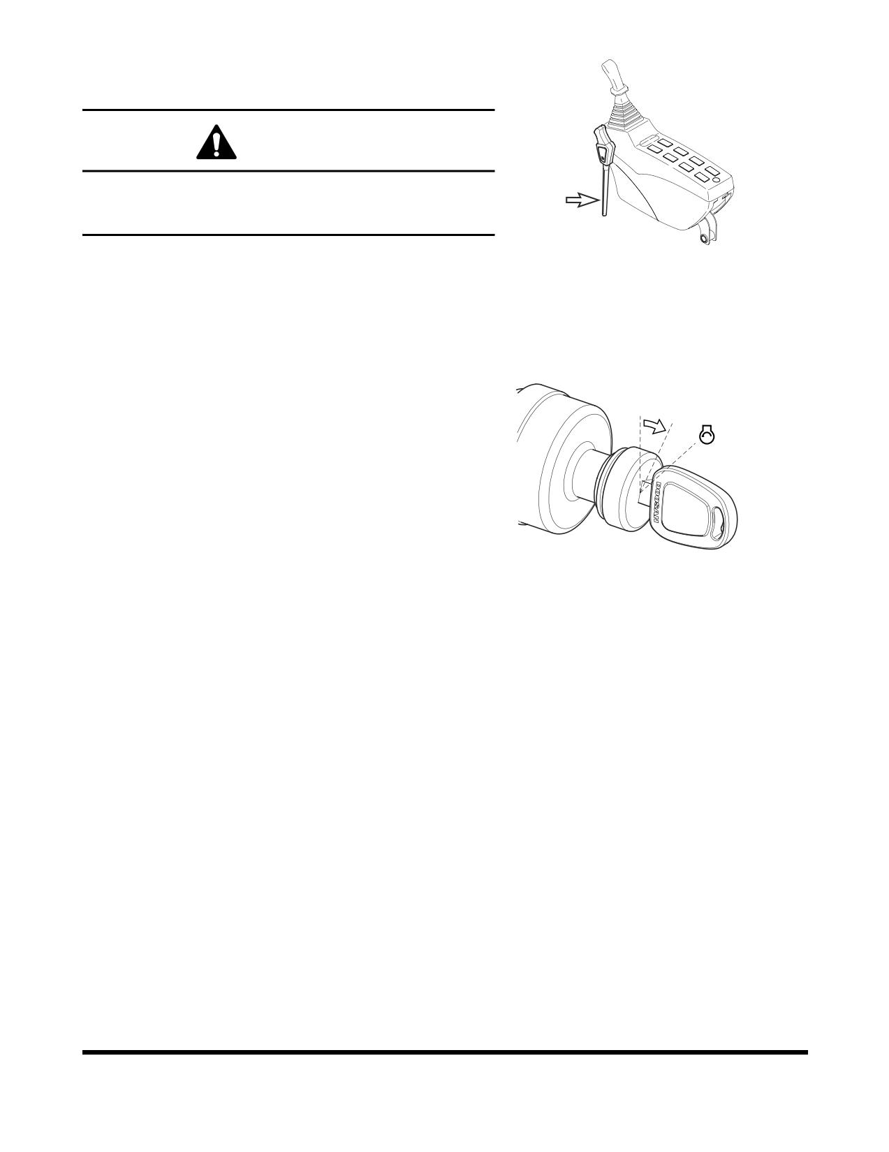
When leaving operator's seat, set the safety lever to
"LOCK" (Figure 1) position, if not a serious accident could
occur by accidentally moving the travel or work levers.
FG000211
1.
Set safety lever on "LOCK" (Figure 1).
Figure 1
2.
Fasten seat belt. Check for proper operation and condition.
3.
Set all operation levers in "NEUTRAL."
NOTE:
Be careful not to touch any switches when
starting engine.
4.
Rotate the starter switch to the "I" (ON) position (Figure 2).
Check all indicator lights. A warning buzzer will sound for
about two seconds. After two seconds, all lights except the
O I
following will turn "OFF."
•
Charging warning light
•
Engine oil pressure warning light
•
Engine coolant temperature gauge
•
Fuel gauge
•
Hydraulic oil temperature gauge
FG000084
Figure 2
•
Engine rpm (0 rpm) digital readout
NOTE:
If all of the indicator lights do not come "ON"
when the key is first turned, there is a problem.
OP000598
Operation
3-3
Engine Start
WARNING!
Start the engine after sounding horn and making sure that
there are no people or obstacles in the area.
1.
Perform all steps in “Operational Checks Before Starting
Engine” on page 3-3.
2.
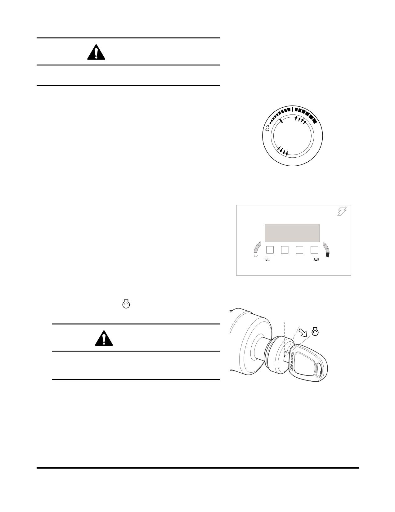
Set engine speed control dial slightly above "LOW IDLE"
(Figure 3).
3.
Sound horn.
HAOB34L
Figure 3
4.
Enter password.
NOTE:
If the security system is "LOCKED," a four-digit
02/05 [MO] 11:30
password will be required to start the engine. If the
system is "UNLOCKED," no password will be
ENTER
required and this display screen will not appear.
PASSWORD
C
H
E/G SPEED
0 RPM
FG001445
Figure 4
" "
5.
Turn starter switch to
(START) position (Figure 5).
Engine should start in approximately five seconds.
O I
WARNING!
If the engine does not start after approximately fifteen
seconds of cranking, release the starter switch. Wait
about five minutes and repeat above step.
6.
After engine has started, release key. Key will return to the
FG000085
"I" (ON) position (Figure 5).
Figure 5
7.
Follow procedures in “Hydraulic System Warm-up” on
page 3-9.
Operation
OP000598
3-4
8.
After warming unit, check all operating indicators to make
sure that all engine systems (oil pressure, coolant, etc.) are
4
5
6
7
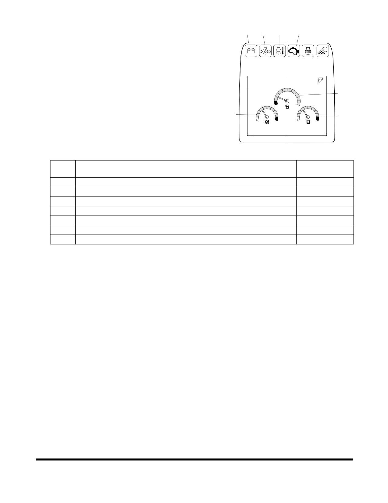
in the normal operating range. If any problems are noticed,
shut down engine. Normal indicators are:
CHECK
02/05 [MO] 11:30
2
1
3
E/G SPEED
1700 RPM
FG000092
Figure 6
INDICATOR
No.
INSTRUMENT PANEL LIGHT OR GAUGE
READING
1
Engine Coolant Temperature Gauge
Blue Range
2
Fuel Gauge
Blue Range
3
Hydraulic Oil Temperature Gauge
Blue Range
4
Charging Warning Light
OFF
5
Engine Oil Pressure Warning Light
OFF
6
Engine Coolant Temperature Warning Light
OFF
7
Engine Check Warning Light
OFF
9.
Check color of exhaust smoke.
•
No color or light blue - Engine is running in good
condition.
•
Black - Incomplete combustion. Check cause.
•
White or dark blue - Engine is burning engine oil.
Check cause.
10.
Check for usual engine vibration and noises. If any are
heard or felt, investigate cause.
NOTE:
If engine coolant temperature gauge pointer
moves into the red zone, the engine coolant
temperature warning light will turn "ON," a
warning buzzer will sound, and the engine
speed will be automatically reduced. Allow the
engine to run at low idle speed until the
temperature gauge registers in the blue zone
again. When the blue zone is reached, allow the
engine to idle for an additional three - five
minutes before shutting down the engine. If not
allowed to idle, heat surge may develop which
will damage the engine. Allowing the engine to
idle will dissipate heat. Check the coolant level,
look for a loose fan belt, inspect for debris
around radiator, and so on.
OP000598
Operation
3-5
Cold Weather Starting
WARNING!
DO NOT USE STARTING FLUIDS. The preheat system could
cause the starting fluid to explode. Starting fluids should
never be used.
1.
Perform all steps in "Operational Checks Before Starting
Engine."
2.
Set engine speed control dial slightly above "LOW IDLE"
(Figure 7).
3.
Sound horn.
HAOB34L
Figure 7
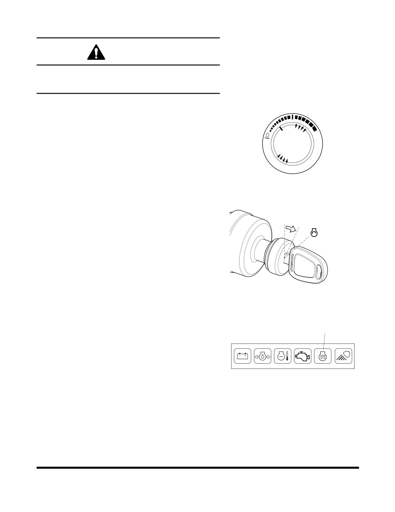
4.
Turn starter switch to the "I" (ON) position (Figure 8). When
preheat cycle is completed, the preheat indicator light (1,
Figure 9) will turn "OFF."
O I
FG000084
Figure 8
1
CHECK
FG000217
Figure 9
Operation
OP000598
3-6
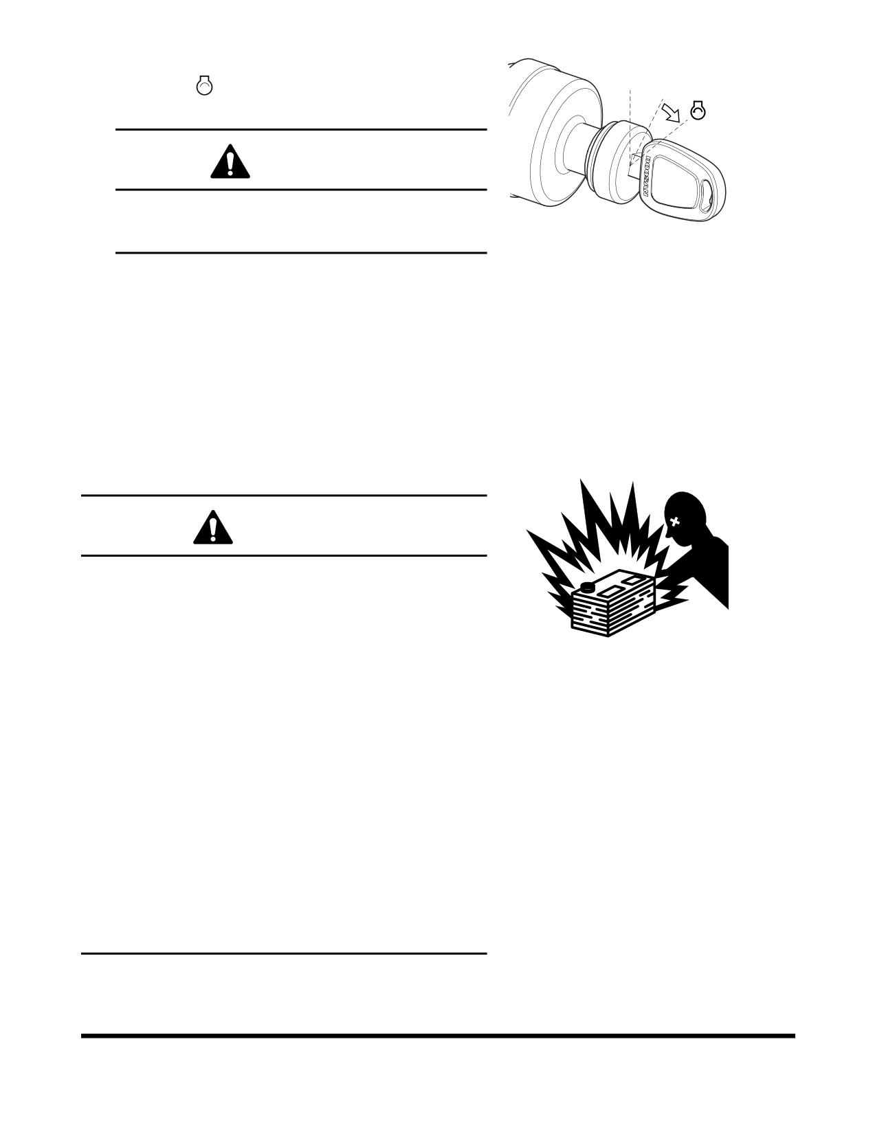
5.
After the preheat completion, immediately turn starter
" "
switch to
(START) position (Figure 10). Engine
O I
should start in approximately five seconds.
WARNING!
If the engine does not start after approximately fifteen
seconds of cranking, release the starter switch. Wait
about five minutes and repeat above step.
FG000085
Figure 10
6.
After engine has started, release key. Key will return to the
"I" (ON) position (Figure 10).
7.
After the engine starts, check all operating indicators to
make sure that all engine systems (oil pressure, coolant,
etc.) are in the normal operating range. If any problems are
noticed, shut down engine.
8.
Follow "Hydraulic System Warm-up" procedures in this
section. (See page 3-9)
Starting Engine With a Booster Cable
WARNING!
1.
An explosive gas is produced while batteries are in
use or being charged. Keep flames or sparks away
from the battery area.
2.
Charge batteries in a well ventilated area.
HAOA440L
3.
Always wear eye protection when starting a machine
Figure 11
with jumper cables.
4.
Improper jump starting procedures can cause an
explosion resulting in personal injury.
5.
Jump start vehicles on dry ground or concrete. Do not
jump start the machine on a steel floor, because the
floor is always grounded.
6.
When starting from another machine, make sure the
machines do not touch.
7.
Always connect the auxiliary battery positive
(+)
terminal too depleted battery positive (+) terminal first.
Then connect auxiliary battery negative (-) terminal to
the frame of the depleted battery machine second.
8.
Connect positive cable first when installing cables and
disconnect the negative cable first when removing.
OP000598
Operation
3-7
IMPORTANT
The machine has a
24V (-) negative ground electrical
system. Use the same capacity 24V booster batteries when
jump starting engine.
If the batteries are drained during starting procedures, jump start
engine using auxiliary or booster batteries according to the
following procedure;
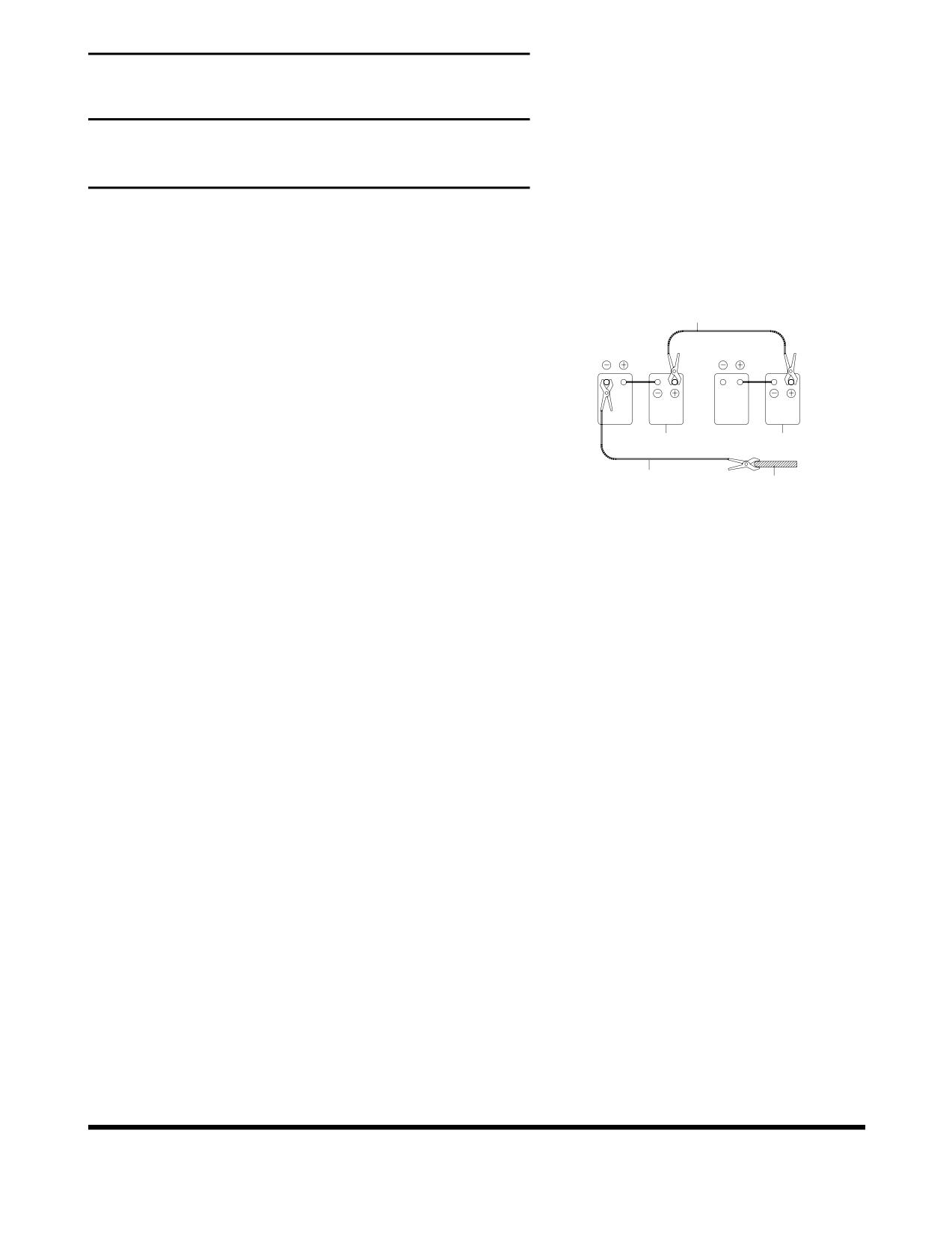
Connecting the Booster Batteries
1
1.
Shut down engine of the machine on which booster
RED
batteries (3, Figure 12) are mounted.
2.
Connect one end of red cable (1, Figure 12) to the positive
(+) terminal of the machine batteries (4), and the other end
to the positive (+) terminal of the booster batteries.
3.
Connect one end of black cable (2, Figure 12) to the
3
4
negative (-) terminal of the booster batteries (3), and then
BLACK
make ground connection to the upper frame (5) of the
2
5
machine to be started with the other end of black (-) cable
ARO0440L
(2, Figure 12). When making the last connection to upper
Figure 12
frame, be sure to connect the cable end as far away from
the machine batteries as possible. DO NOT CONNECT
DIRECTLY TO THE NEGATIVE BATTERY TERMINAL.
4.
Start the engine.
Disconnecting the Booster Batteries
1.
Disconnect black negative (-) cable (2, Figure 12) from the
machine frame (5) first.
2.
Disconnect the other end of black negative (-) cable (2,
Figure 12) from the booster batteries (3).
3.
Disconnect red positive (+) cable (1, Figure 12) from the
booster batteries (3).
4.
Disconnect red positive (+) cable (1, Figure 12) from the
machine batteries (4).
Operation
OP000598
3-8
Hydraulic System Warm-up
WARNING!
If a problem or abnormal operation occurs, immediately
shut down engine. Allow excavator to reach normal
operating temperature before starting work, especially in
cold weather.
The correct operating temperature of the hydraulic oil is 50° -
80°C (120° - 175°F). Make sure to follow the procedures listed
here for hydraulic fluid warm-up.
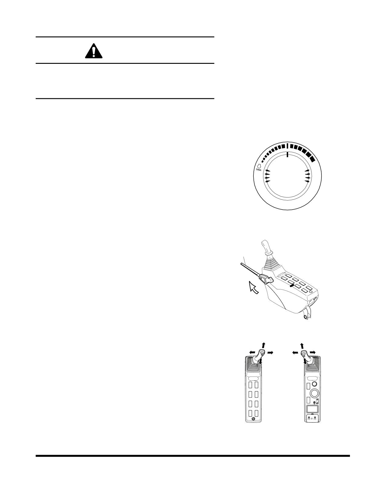
1.
Run engine for approximately five minutes set at the
middle of the speed range, without a load.
HAOB410L
Figure 13
2.
Set safety lever (1, Figure 14) on "UNLOCK" position.
1
FG000093
Figure 14
3.
Slowly cycle boom, arm and bucket cylinders about five
times without a load to circulate the oil through the system.
Do this for five minutes.
4.
Check for clearance and fully raise the front attachment.
Swing clockwise 3 revolutions. Swing counterclockwise 3
revolutions.
5.
Travel forward and reverse at low speed for two
revolutions of the drive sprocket.
FG000380
Figure 15
OP000598
Operation
3-9
Hydraulic System Warm-up - Cold
Weather
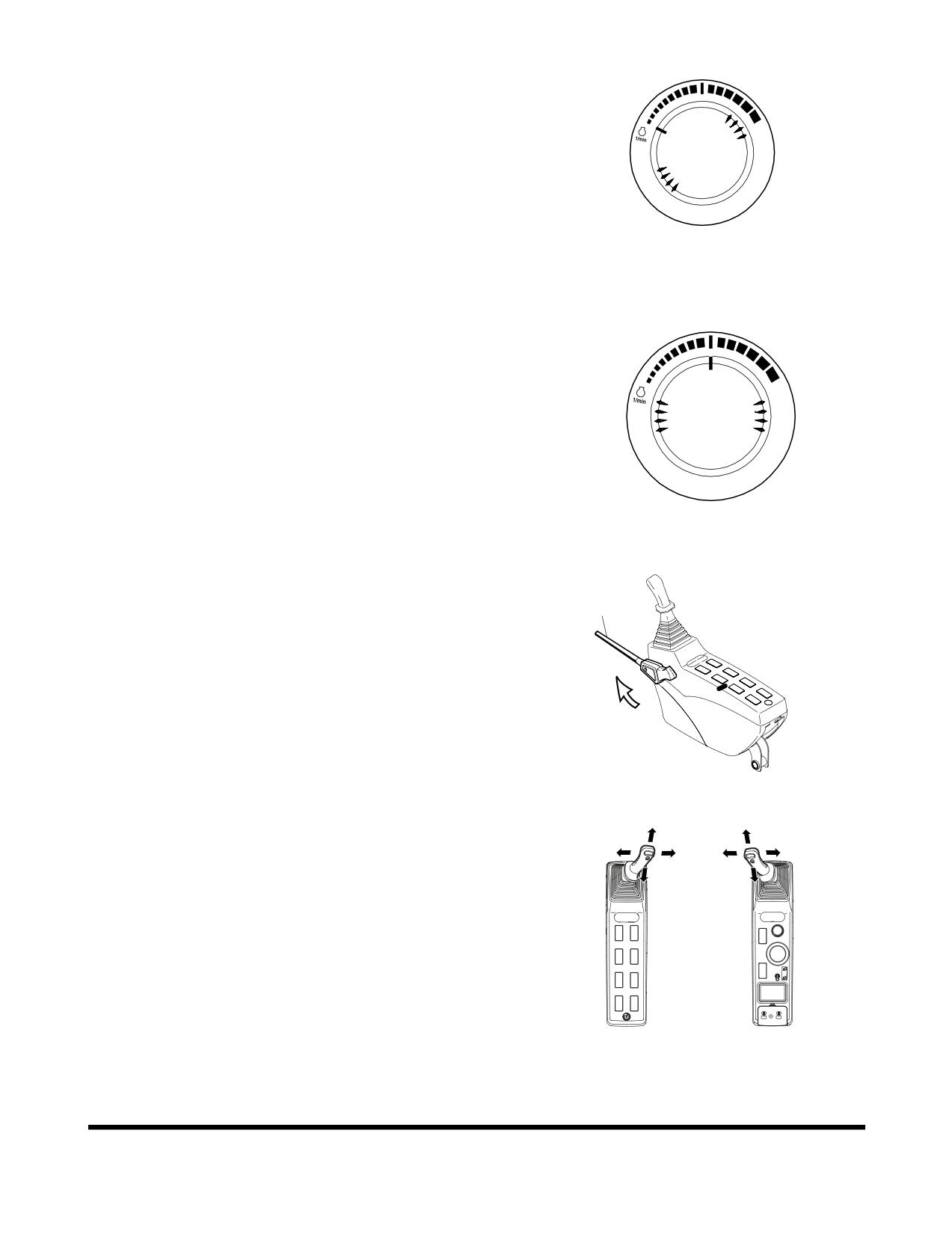
1.
Run engine at "LOW IDLE" (no load) for five minutes
(Figure 16).
HAOB290L
Figure 16
2.
Run engine for approximately five minutes set at the
middle of the speed range, without a load (Figure 17).
HAOB410L
Figure 17
3.
Set safety lever (1, Figure 18) on "UNLOCK" position.
1
FG000093
Figure 18
4.
Slowly cycle boom, arm and bucket cylinders about five
times without a load to circulate the oil through the system.
Do this for five minutes.
FG000380
Figure 19
Operation
OP000598
3-10
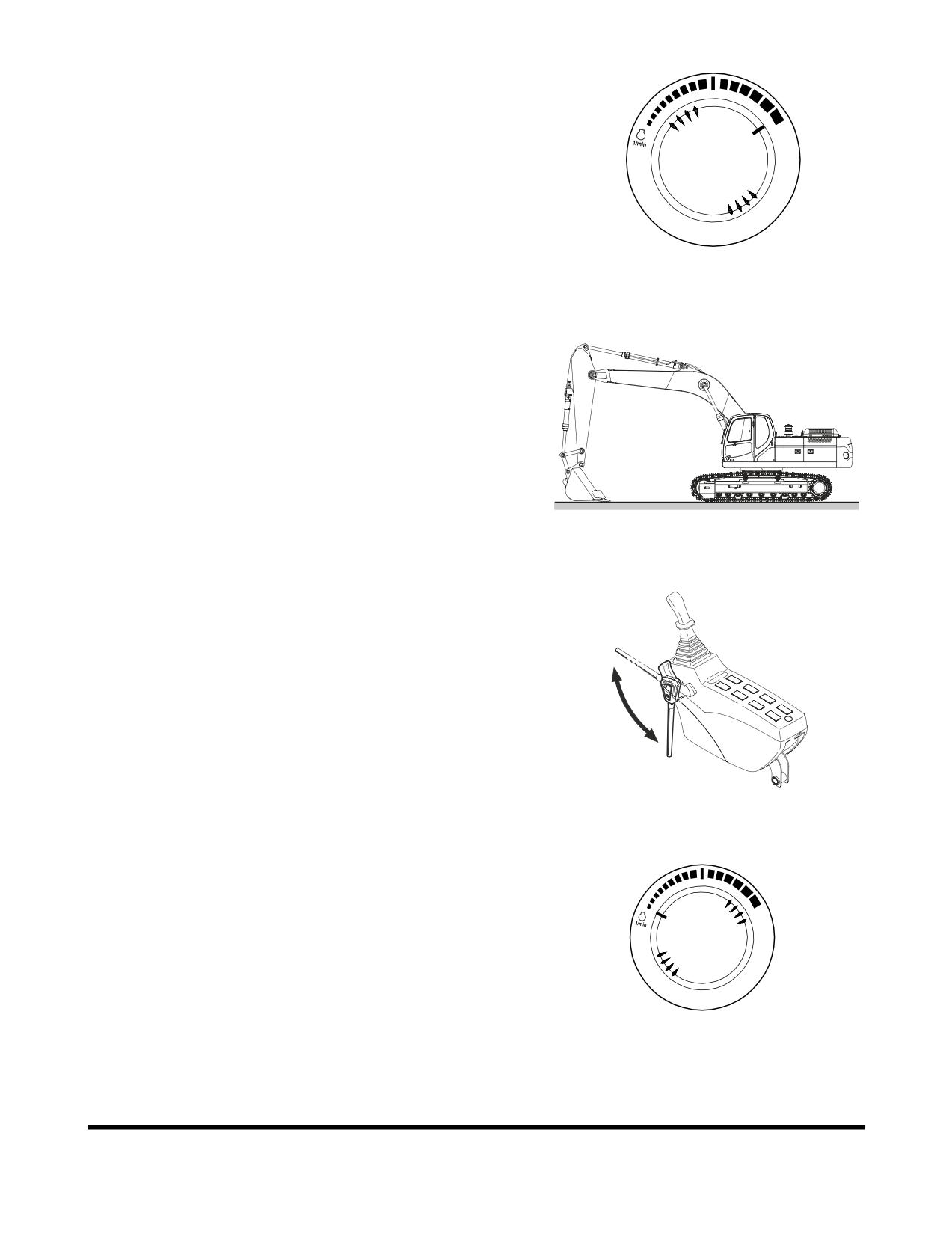
5.
Set engine speed control dial to "HIGH IDLE" (Figure 20).
6.
Repeat Step 4 for five minutes. If working speeds continue
to be slow, continue to operate, but use extreme caution
because the machine function may be erratic.
7.
Check for clearance and fully raise the front attachment.
Slowly swing clockwise
3 revolutions. Slowly swing
counterclockwise 3 revolutions.
8.
Travel forward and reverse at low speed for two
revolutions of the drive sprocket.
HAOB550L
Figure 20
Engine Shut Down
NOTE:
Allow engine to idle for three - five minutes before
shutting down the engine. If not allowed to idle, heat
surge may develop which will damage the engine.
Allowing the engine to idle will dissipate heat.
1.
Park excavator on level and firm ground.
2.
Lower front end attachment to ground and make sure all
operating controls are in "NEUTRAL."
FG000111
Figure 21
3.
Set safety lever on "LOCK" position (Figure 22).
Unlock
lock
FG001091
Figure 22
4.
Set engine speed control dial to "LOW IDLE" (Figure 23).
Allow engine to idle for three - five minutes.
HAOB290L
Figure 23
OP000598
Operation
3-11

5.
Shut down engine by turning key to "O" (OFF) position
(Figure 24).
O I
6.
Remove key from starter switch.
Check and Confirmation After Stopping
Engine
1.
Repair excavator, if there are any coolant or oil leaks.
2.
Inspect front attachment and under carriage for abnormal
FG000390
appearances. Correct any problems.
Figure 24
3.
Fill fuel tank.
4.
Get rid of any accumulated flammable materials such as
leaves and paper etc. in engine compartment.
5.
Clean all mud, etc. from undercarriage and tracks. Make
sure that all steps and hand holds are clean, and that the
operator's compartment is clean.
Operation
OP000598
3-12
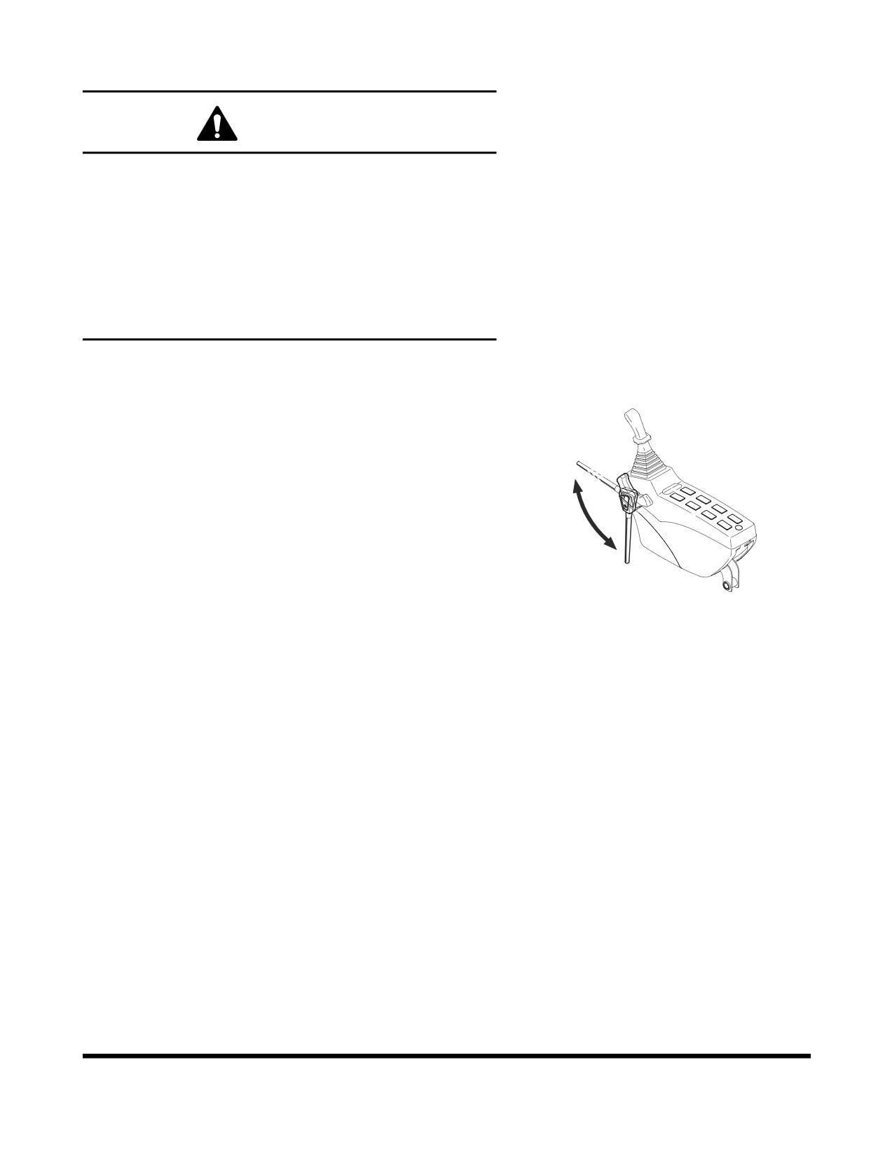
SAFETY LEVER
WARNING!
When stopping engine or leaving the operator's seat,
"LOCK" the safety lever, otherwise, a serious accident may
occur by accidental movement of travel and work levers.
Whenever leaving the operator's seat, make sure the engine
is shut down and the safety lever is "LOCKED."
Especially, when adjusting the seat, control stands, or
raising the front window, lower window, or ceiling cover,
never forget to lock the safety lever in its "LOCKED"
position.
Be careful not to move the work levers (joysticks) when moving
safety lever.
1.
Push safety lever (Figure 25) down into the "LOCKED"
position. When safety lever is in the "LOCKED" position,
the front attachment, swing and travel movement will be
disabled even though a lever is moved.
Unlock
NOTE:
Lower bucket (front attachment) to ground.
Place all control levers in "NEUTRAL" and shut
down engine, before using the safety lever.
2.
Set safety lever (Figure
25) on "RELEASE/UNLOCK"
position, by pulling it up before starting work.
lock
NOTE:
When the engine is not running, but the safety
FG001091
lever is "RELEASED" and the starter key is
Figure 25
tuned "ON," moving the work levers (joysticks)
may result in movement. The charged
accumulators in the system will provide pilot
pressure for control valve spool movement.
OP000598
Operation
3-13
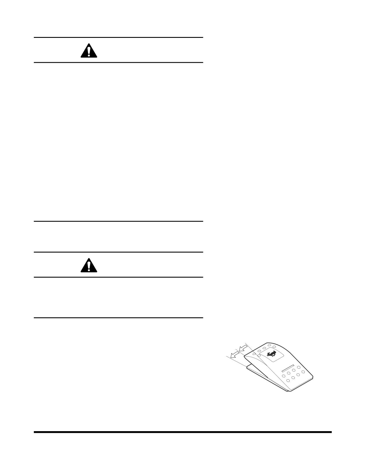
TRAVEL
WARNING!
1.
Before operating the travel levers, make sure that you
know in which direction the machine is pointing. Look
at the end of the track assemblies. If the drive motors
are visible while sitting in the operator's seat, you are
looking at the back end of the track assembly
(therefore, you are looking backwards). In this case,
the response of the travel levers will be the reverse of
normal operation.
2.
Before moving, make sure that there are no personnel
in the way or on the machine. Sound the horn to alert
workers that you are about to move the machine.
3.
Be sure the path is clear during travel.
4.
Use extreme caution when reversing travel. Be sure
there is a clear path behind the machine.
5.
Make sure to operate the travel control levers
smoothly to avoid sudden starts or stops.
6.
Before leaving the operator's seat, make sure to lock
out all control systems and shut down the engine to
avoid accidental activation.
Automatic Travel Speed Control
WARNING!
Do not change the travel mode while traveling. Always use
speed mode "O" when traveling down a slope. It is very
dangerous to change to speed modes indicated "I" or "II"
while going down a slope. Only change travel mode after
coming to a complete stop.
Two travel speed ranges can be selected by using the travel
speed selector switch on the control panel (Figure 26).
O
"O" (LOW) - In this position low travel speed and a higher torque
I
are selected.
II
"I" (HIGH) - In this position high travel speed and a lower torque
are selected.
"II" (AUTOMATIC) - Setting the control at the "II" position
enables the machine to change to a different speed range
automatically. This change happens automatically depending on
the hydraulic oil pressure in the travel circuit. When hydraulic oil
FG000023
pressure rises, the travel speed is automatically set to low.
Figure 26
Operation
OP000598
3-14
An example is if the machine is traveling on a flat, solid surface,
the higher speed range would be used. When a slope is
encountered, the speed drops and the travel circuit hydraulic
pressure rises, causing the control circuit to shift to the higher
torque, lower speed range.
OP000598
Operation
3-15