Doosan DX140LC. Operation and Maintenance Manual (2007) - page 7
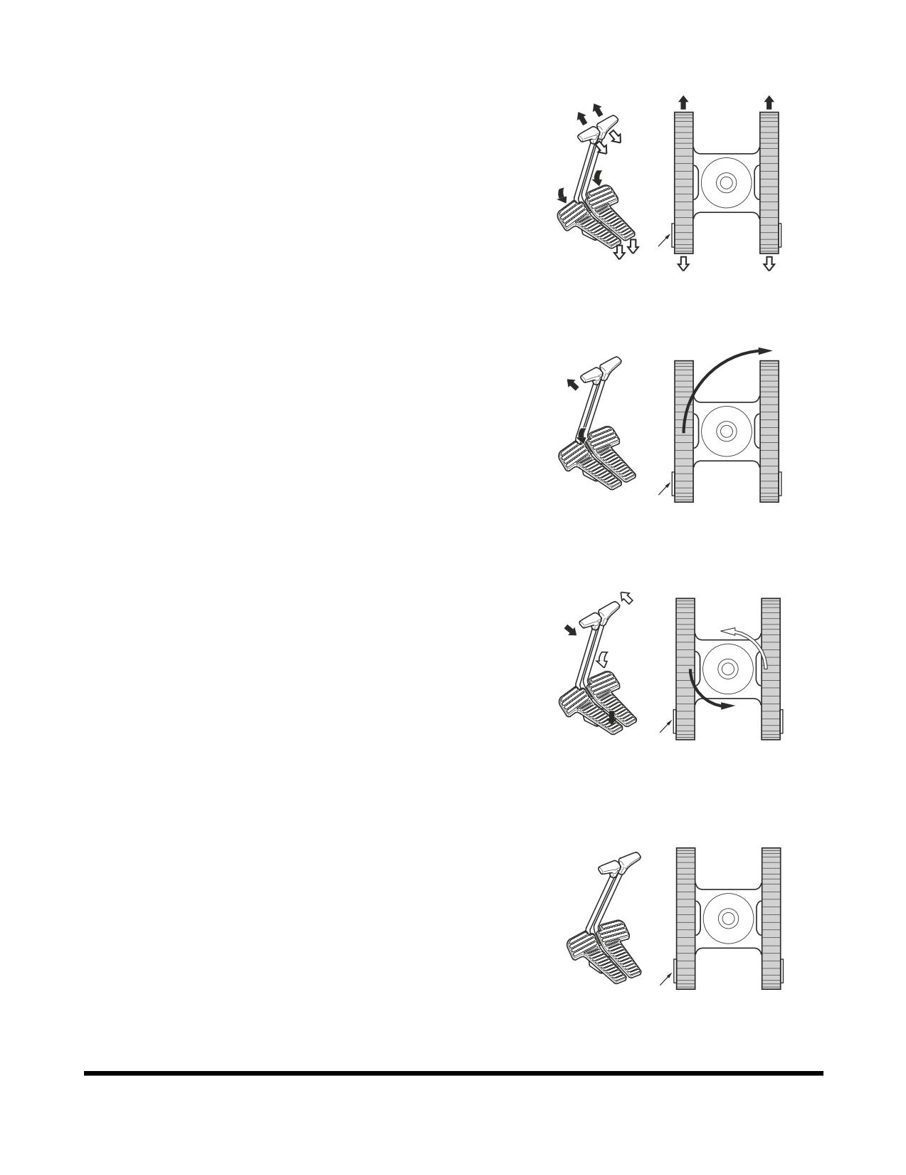
Travel Control Lever Operation
1.
To travel straight (Figure 27), push both travel control
levers/pedals fully forward or backwards. The farther the
levers/pedals are pressed, the faster the travel speed.
NOTE:
"X" is the sprocket end of the track.
"X"
FG000303
Figure 27
2.
Pivot turns (Figure 28) are made by rotating only one track
forward or backward. The machine will pivot on the
nonmoving track.
NOTE:
"X" is the sprocket end of the track.
"X"
FG000304
Figure 28
3.
Spin turns (Figure 29) are made by rotating one track
forward and one track backward. The machine will spin
around its center point, thus counterrotating.
NOTE:
"X" is the sprocket end of the track.
"X"
FG000305
Figure 29
4.
Stopping travel (Figure 30) - Returning travel levers to
"NEUTRAL" position will automatically apply brakes and
stop excavator.
NOTE:
"X" is the sprocket end of the track.
"X"
FG000306
Figure 30
Operation
OP000598
3-16
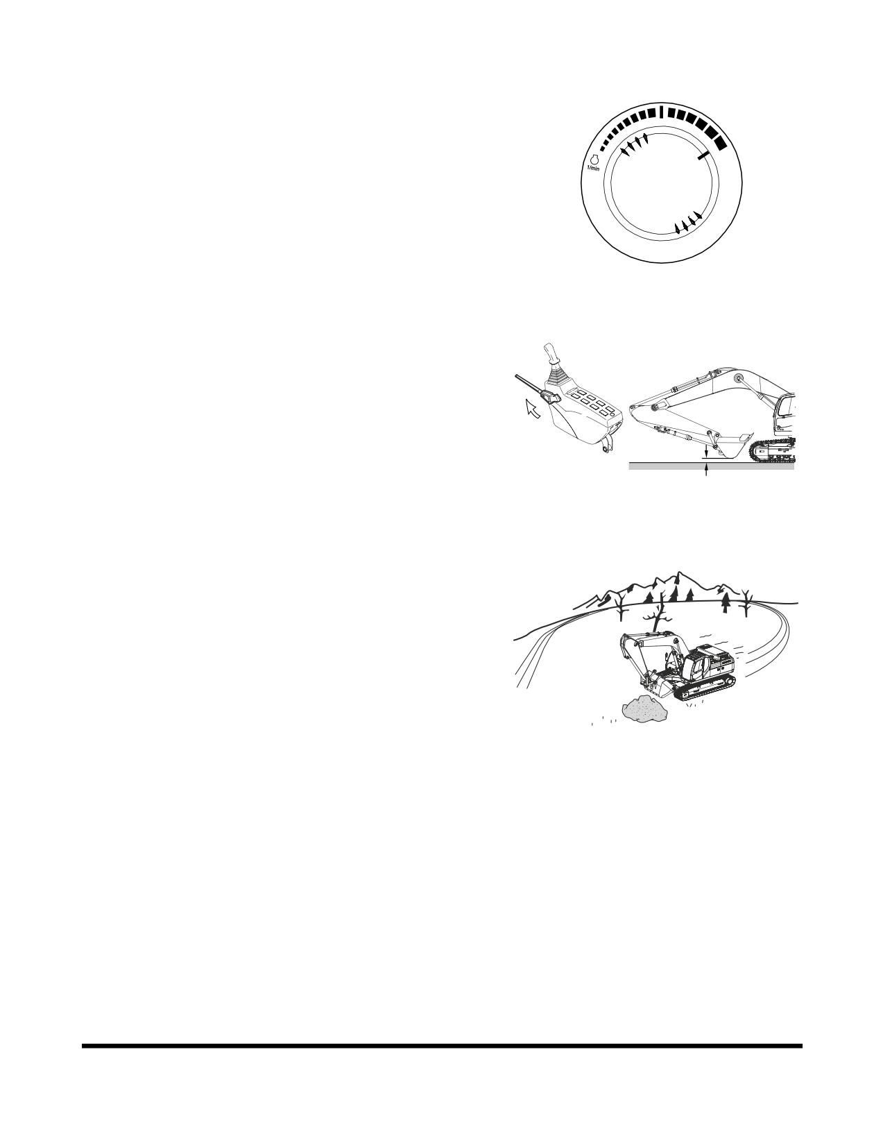
General Travel Instructions
1.
Set engine speed control dial (Figure 31) on desired
speed.
HAOB550L
Figure 31
2.
Set safety lever on "UNLOCK" position, and folding the
front, raise it 40 - 50 cm (16 - 20 in) above ground. See
Figure 32.
40 ~ 50 cm
FG000123
Figure 32
3.
When possible, travel on firm, level ground. Avoid sudden
movements and sharp turns.
4.
When traveling on rough ground, travel at a slow speed
[1.0 - 1.5 km/h (0.62 - 0.93 MPH)]. Reduced engine speed,
to avoid shock loading the equipment. Be careful that an
excessive force is not added to equipment by touching or
climbing on rocks.
FG000423
Figure 33
OP000598
Operation
3-17
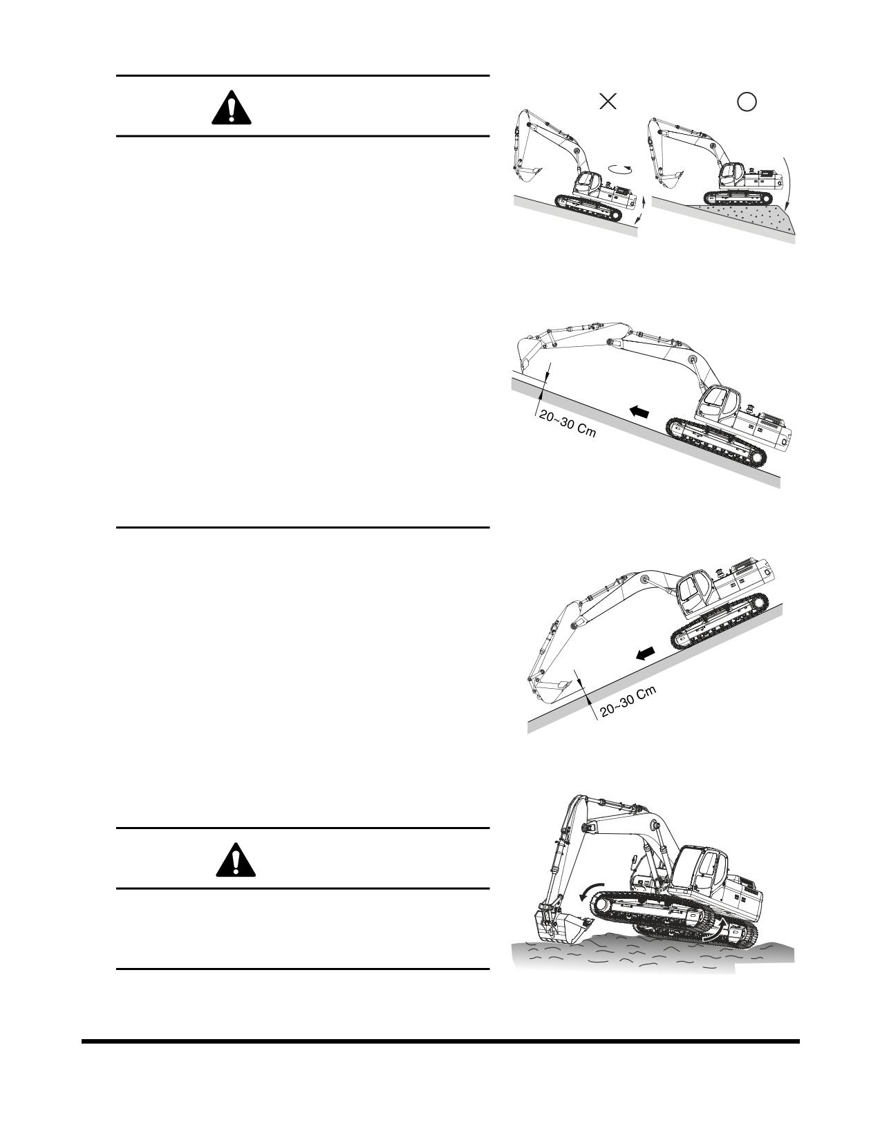
5.
On rough, frozen or uneven terrain, travel slowly.
WARNING!
When traveling, keep bucket from 20 - 30 cm (8 - 12 in)
above ground.
Do not travel backward on a slope.
Never turn or travel crosswise on a slope.
Choose a safe alternate route before climbing a slope.
FG000212
If excavator starts to slip or becomes unstable, lower
Figure 34
the bucket immediately into the ground, using it as a
brake.
Avoid working on slopes, because there is a danger of
overturning by becoming unbalance while swinging
and performing front attachment operations.
It is very dangerous to swing towards bottom of slope
with a loaded bucket.
In unavoidable cases level the slope with fill soil, to
make the vehicle as horizontal as possible. See Figure
34.
Do not travel on slopes more than 30° due to turnover
FG000126
danger.
Figure 35
6.
Travel straight up or down slopes, never diagonally across
the slope. See Figure 35 and Figure 36. Extend the arm
and lower the boom to keep the bucket about 20 - 30 cm (8
- 12 in) off the ground. If the machine starts to slide or
becomes unstable, lower the bucket to regain control. If the
engine stalls, lower the bucket, make sure that all controls
are in the neutral position and restart the engine.
NOTE:
Even though engine stops on a slope, do not
operate swing control. The hydraulic
accumulators may cause the unit to swing.
FG000128
NOTE:
Do not open or close operator's door on a slope.
Figure 36
Make sure door is latched.
7.
If dirt or mud builds up in the track frame, raise each track
and rotate and clean that track.
CAUTION!
When using the boom and arm to lift any portion of the
machine, roll the bucket until the round base is against
the ground. The angle of the arm to the boom should
be at 90°.
FG000376
Figure 37
Operation
OP000598
3-18
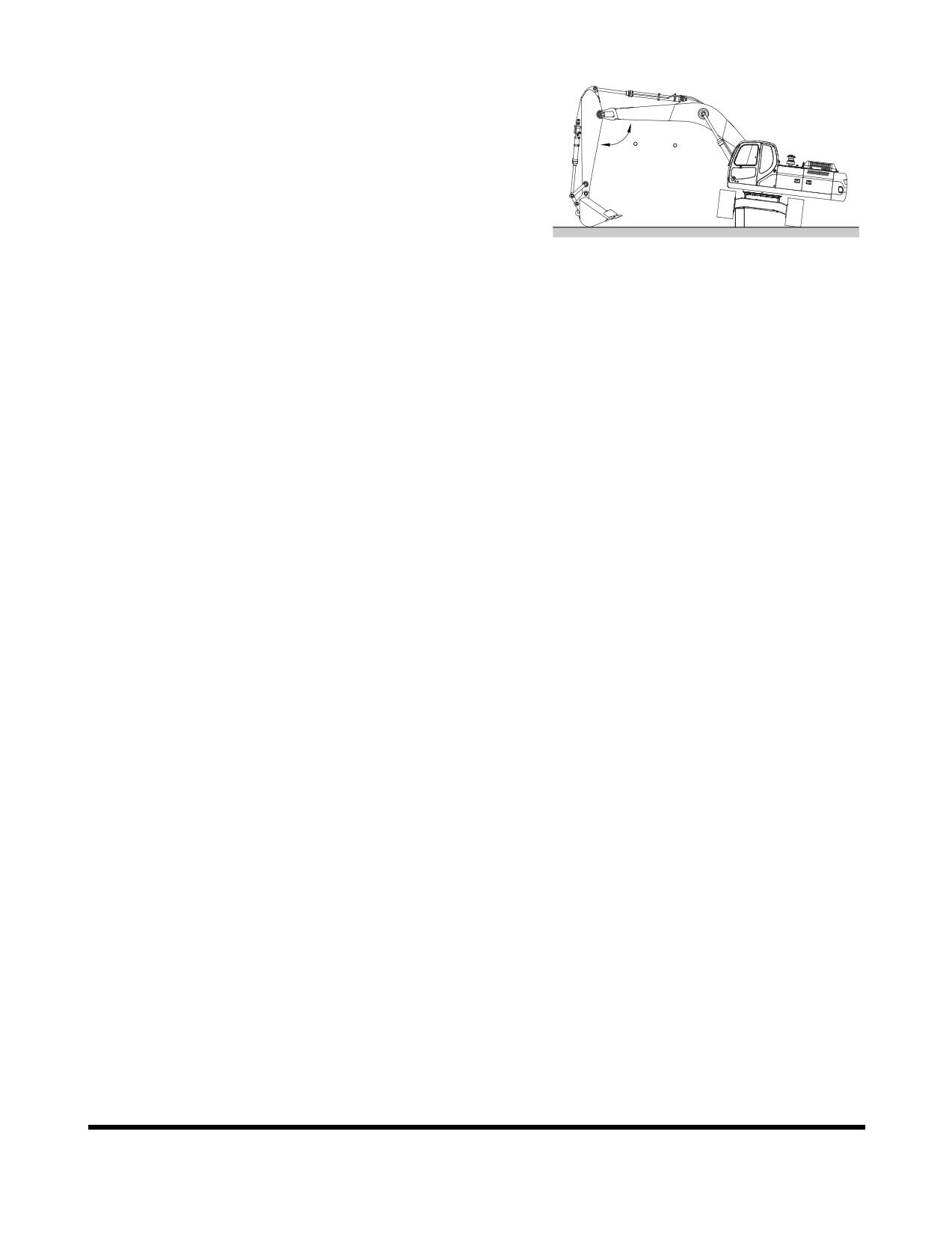
Make sure that the material buildup has been cleared. See
Figure 37 and Figure 38.
8.
The excavator can travel in water that comes up to center
of upper carriage rollers. Make sure that footing is solid so
that the machine will not sink. See “Working in Water” on
90 ~ 110
page 3-31.
NOTE:
If the machine is submerged to the point that
water or mud gets into the swing bearing or
center joint, stop machine operation. Remove
the machine from the submerged location to
FG000345
firm, dry ground. Do not operate until proper
Figure 38
inspection and maintenance have been
completed. Refer to the Shop Manual or contact
your distributor.
OP000598
Operation
3-19
OPERATING INSTRUCTIONS
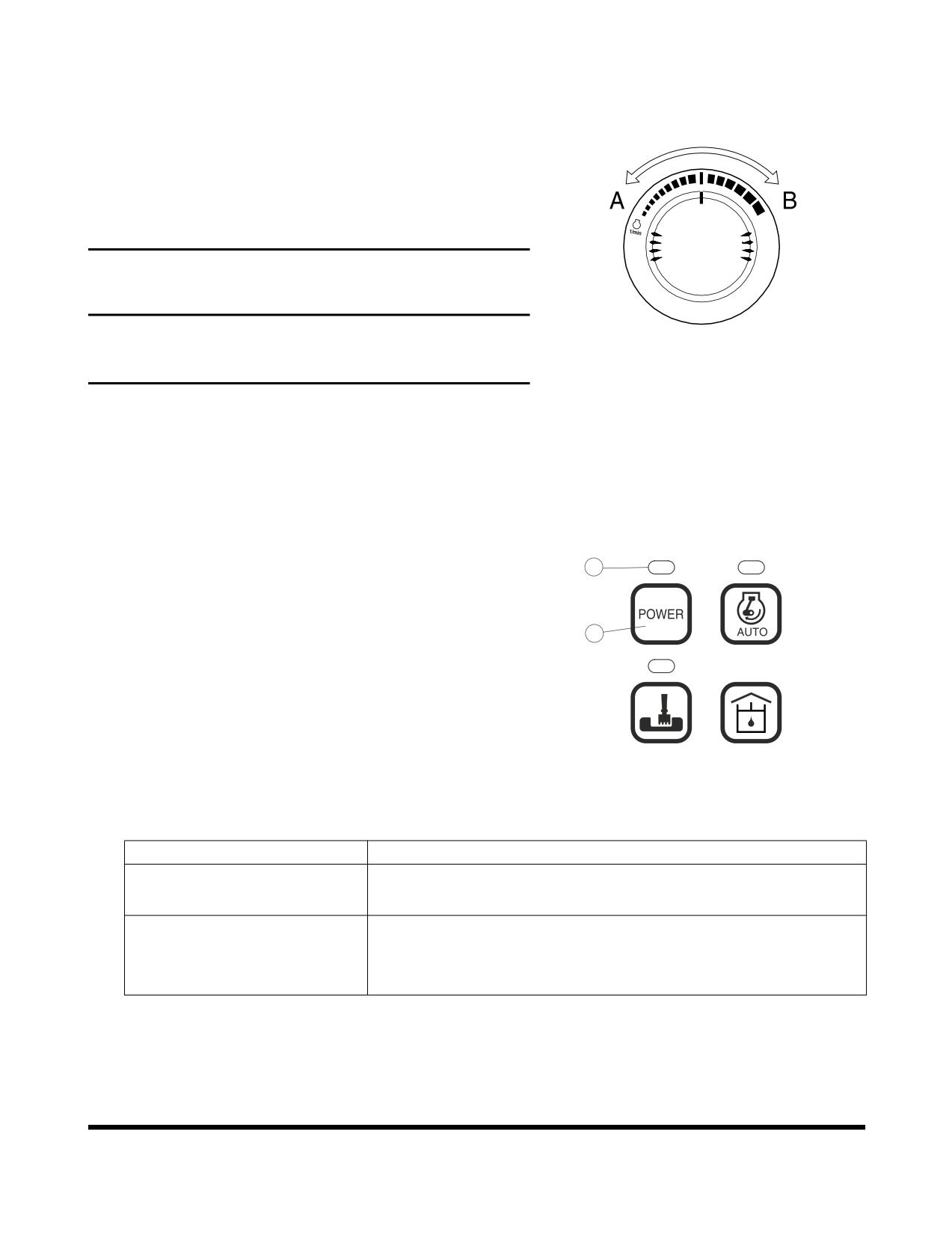
Engine Speed Control
Engine speed can be manually adjusted using the engine speed
control dial, Increase engine speed by rotating the control knob
clockwise. Decrease engine speed by rotating the control knob
counterclockwise.
IMPORTANT
The engine speed control system has been set at the
HAOA690L
factory and should not require adjustment as part of routine
Figure 39
maintenance.
Mode Selection
More efficient work can be done by choosing a proper power
and work mode combination, suitable to type of work and
conditions. Use the mode selection according to following guide.
Power Mode
2
1.
When the starter switch is turned "ON" the power mode is
automatically defaulted to the standard setting.
2.
Select a proper power mode using button (1, Figure 40)
1
before starting work.
1
2
3.
When the power mode button (1, Figure 40) is pressed, a
signal sounds, changing the power mode to either "ON" or
"OFF." When the power mode is turned "ON," the LED
indicator (2, Figure 40) turns "ON."
5
6
FG000114
Deactivate the power mode by pressing it a second time.
Figure 40
When the power mode is turned "OFF," the LED indicator
(2, Figure 40) turns "OFF" and the power mode returns to
the standard mode.
Mode
Selection Point
• General work.
STANDARD MODE
• Minimize fuel consumption.
• Required to perform heavy work in a short period of time.
POWER MODE
• Fast speed loading.
• Fast speed travel.
Operation
OP000598
3-20
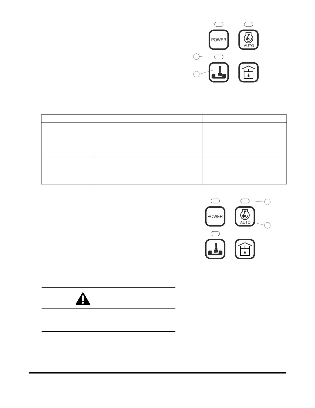
Work Mode
1.
When the starter switch is turned "ON" the work mode is
automatically defaulted to the digging mode.
2.
Select the work mode using button (3, Figure 41) before
starting work.
1
2
4
3.
When the work mode button (3, Figure 41) is pressed, a
signal sounds, changing the work mode to either "Digging
Mode" or "Trenching Mode." When the trenching mode is
3
selected, the LED indicator (4, Figure 41) turns "ON."
5
6
When the digging mode is selected, the LED indicator (4,
FG000115
Figure 41) turns "OFF."
Figure 41
4.
When the trenching mode is selected, the control valve is
set to optimum condition for trenching work.
Mode
Selection Point
Feature of Control
• General excavation.
General standard.
• Loading dump trucks.
DIGGING MODE
• Lifting and transport of heavy objects.
• Breaker.
• Trenching.
TRENCHING
The swing is faster and stronger
• Excavating of side wall.
MODE
than boom or arm.
• Required to constant swinging.
Auto Idle Mode
6
1.
The system will automatically reduce engine speed to idle
speed approximately four seconds after all of the control
levers are in the neutral position. When a pilot function is
activated, engine speed is automatically returned to the
5
1
2
preselected range.
2.
When the starter switch is turned "ON," the work mode is
automatically defaulted to "AUTO IDLE."
3.
When the LED indicator (6, Figure 42) is turned "ON," the
5
6
auto idle function is activated. Deactivate the auto idle
FG000116
function by again pressing the auto idle selector button (5,
Figure 42
Figure 42). At this time the LED indicator will be turned
"OFF."
WARNING!
Turn "OFF' auto idle function when performing work in
close operating area, i.e., work in a narrow area and
loading / unloading on or off a trailer.
OP000598
Operation
3-21
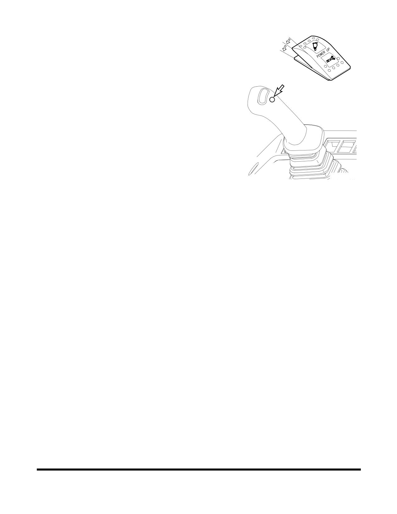
Boost Mode
I
1.
Power boost switch is used to gain maximum digging
O
force.
I
2.
The power boost is activated while the lower button is
being pressed on top of the right-hand work lever
(joystick). The breaker / boost / shear selector switch must
be in the "O" (BOOST) position.
NOTE:
The power boost mode does not affect forward
and reverse travel.
Do not use this switch for more than ten
seconds.
FG000117
Figure 43 RIGHT-HAND WORK LEVER
(JOYSTICK)
Operation
OP000598
3-22
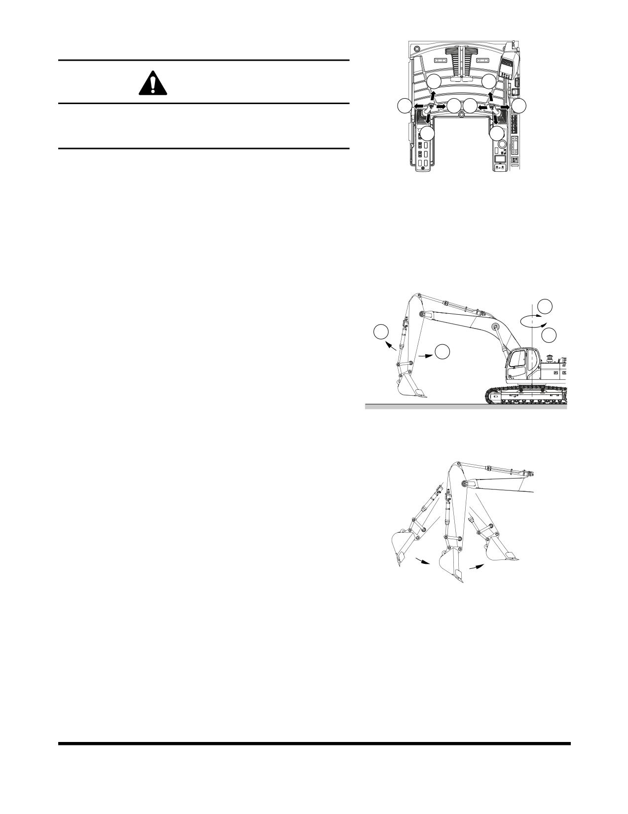
Work Levers (Joysticks) (ISO Style)
1
5
WARNING!
3
4
7
8
Check surrounding area before swinging. When operating a
lever while in auto idle, do it carefully, because the engine
2
6
speed will increase rapidly.
NOTE:
When starting work, move work levers (joysticks)
FG000381
slowly and check movement of swing and front
Figure 44
attachment.
This equipment is manufactured using the lever configuration
described in ISO standards. Do not change valving, hoses, etc.,
that would change this standard. The boom, arm and bucket
movements and swing direction of work levers (joysticks) are as
follows:
Left-hand Work Lever (Joystick) (Figure 44 and Figure 45)
1.
Arm dump
4
2.
Arm crowd
1
3
3.
Left swing
2
4.
Right swing
NOTE:
The swing brake is spring applied and
hydraulically released. It is always engaged
when the work lever (joystick) is in "NEUTRAL"
or the engine is shut down.
FG000119
Figure 45
NOTE:
The following is not a mechanical malfunction
but a proper phenomenon of the excavator.
When operating the arm, it may stop
momentarily. When the arm is operated, the
weight of the arm may cause it to move faster
than the amount of oil being supplied.
FG000120
Figure 46
OP000598
Operation
3-23
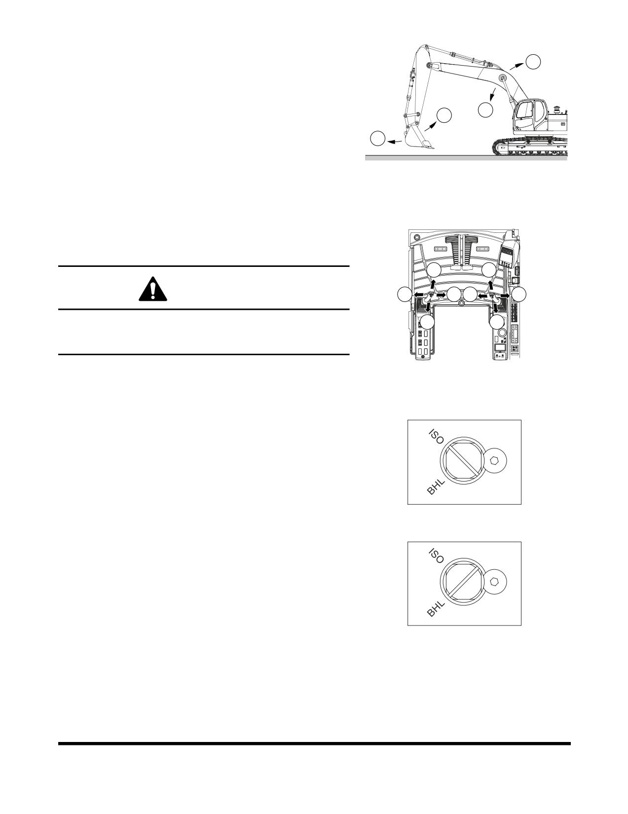
Right-hand Work Lever (Joystick) (Figure 44 and Figure 47)
5.
Boom down
6
6.
Boom up
7.
Bucket crowd
5
8.
Bucket dump
7
NOTE:
Even after stopping the engine, the front can be
8
lowered to the ground by operating work lever
(joystick), by setting safety lever on "UNLOCK"
position and turning starter switch "ON."
FG000121
Figure 47
Change Machine Control Pattern by Select
Valve (If Equipped)
1
5
WARNING!
3
4
7
8
Check surrounding area before swinging. When operating a
2
6
lever while in auto idle, do it carefully, because the engine
speed will increase rapidly.
FG000381
Figure 48
NOTE:
When starting work, move work levers (joysticks)
slowly and check movement of swing and front
<ISO PATTERN>
attachment.
The machine control pattern can easily be changed to the ISO
standard or to the standard backhoe loader hydraulic system
(BHL) by changing the position of the select valve (if equipped).
Use the following procedure to change the position of the select
valve.
The select valve is located in the rear of the cabin.
1.
Rotating spool to the ISO position or to the BHL position.
<BHL PATTERN>
(Figure 49)
FG004954
Figure 49
Operation
OP000598
3-24
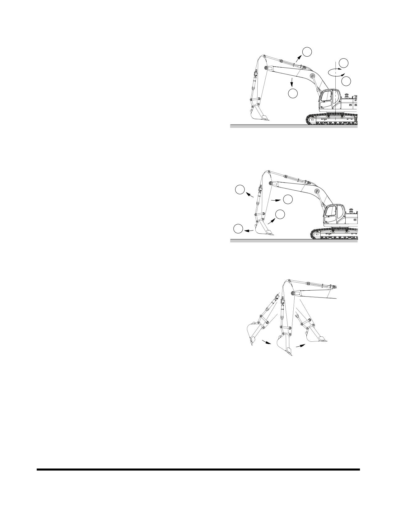
Work Levers (Joysticks) (BHL Style)
Left-hand Work Lever (Joystick) (Figure 48 and Figure 50)
2
1.
Boom down
4
2.
Boom up
3.
Left swing
3
4.
Right swing
1
NOTE:
The swing brake is spring applied and
hydraulically released. It is always engaged
when the work lever (joystick) is in "NEUTRAL"
or the engine is shut down.
FG004951
Figure 50
Right-hand Work Lever (Joystick) (Figure 48 and Figure 51)
5.
Arm dump
6.
Arm crowd
5
6
7.
Bucket crowd
8.
Bucket dump
7
NOTE:
The following is not a mechanical malfunction
8
but a proper phenomenon of the excavator.
When operating the arm, it may stop
momentarily. When the arm is operated, the
FG004952
weight of the arm may cause it to move faster
Figure 51
than the amount of oil being supplied.
NOTE:
Even after stopping the engine, the front can be
lowered to the ground by operating work lever
(joystick), by setting safety lever on "UNLOCK"
position and turning starter switch "ON."
FG000120
Figure 52
OP000598
Operation
3-25
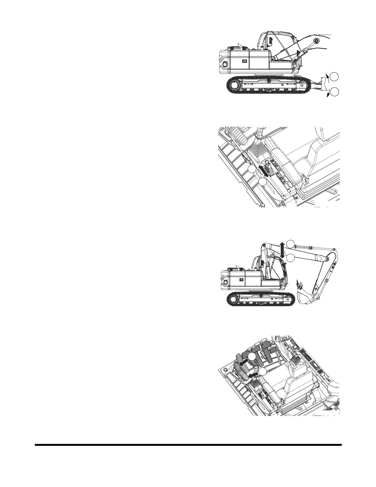
Dozer Blade (Optional)
If the machine is equipped with the optional dozer blade.
The dozer blade control lever is on the left control stand. To
lower blade, push lever forward: to raise blade, pull lever
backwards.
Whenever dozer blade is being used to level ground, make sure
10
to set travel speed control to "LOW SPEED". Attempting to use
dozer blade in "HIGH SPEED" will cause damage to drive
9
system.
FG009722
9.
Blade down
Figure 53
10. Blade up
9
10
FG009730
Figure 54
Two-Piece Boom (Optional)
12
11. Upper Boom down
12. Upper Boom up
11
FG009728
Figure 55
11
12
FG009729
Figure 56
Operation
OP000598
3-26
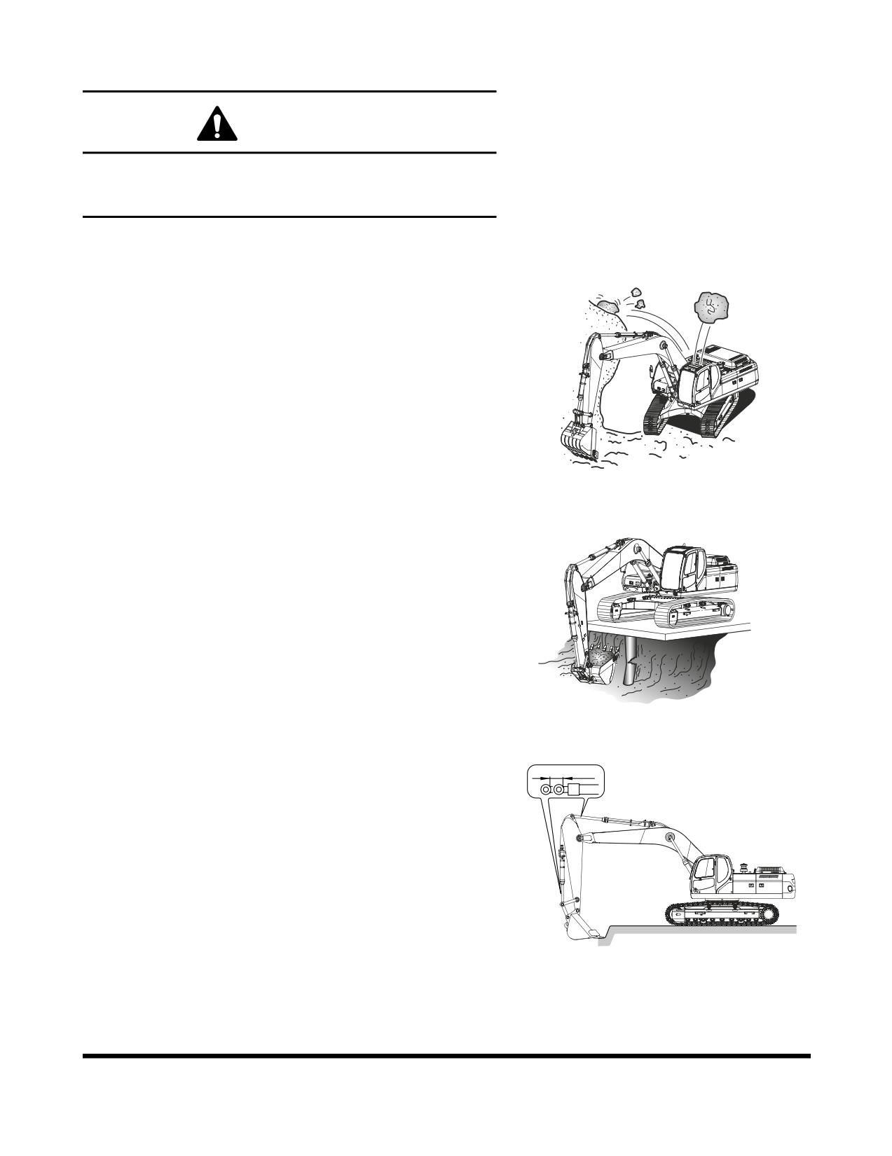
OPERATING PRECAUTIONS
WARNING!
Do not rest your feet on the travel pedals during normal
machine operation. Unexpected machine travel may occur
in this situation.
1.
Before starting work, investigate terrain and soil condition.
Level ground and drain area if necessary.
2.
Install window guards when working where there is a
possibility of falling rocks or other objects.
FG000374
Figure 57
3.
Check strength of supported structures in advance before
working on them. If insufficient, reinforce it. If any doubt
exists about structural strength, refuse to operate unit.
4.
It is possible that the boom, arm or bucket may come into
contact with the upper or lower structure of the machine.
There are digging conditions which could allow this to
happen.
FG000375
Figure 58
5.
Do not continually "bottom out" the hydraulic cylinders.
Machine damage may occur if the cylinders are fully
extended or retracted, example: arm cylinder fully retracted
and the bucket cylinder is extended to rotate the bucket
into the ground.
FG000132
Figure 59
OP000598
Operation
3-27
6.
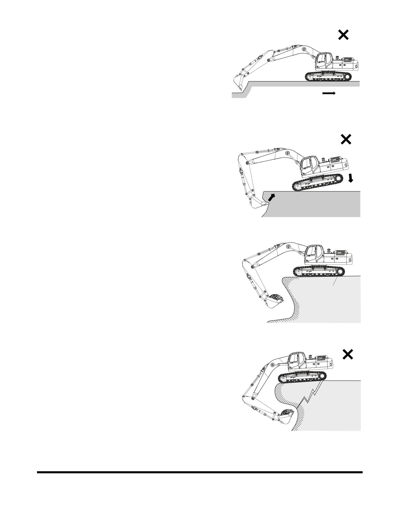
Do not use machine travel or swing when the bucket is in
the ground to provide additional breakout force. See Figure
60.
FG000134
Figure 60
7.
Do not use machine weight to provide additional breakout
force. See Figure 61.
8.
When working on soft or muddy ground, make sure that
the machine is not sinking.
FG000137
Figure 61
9.
When working close to the excavated edge, make sure
that the ground the machine is sitting on is solid. Keep the
travel motors (1, Figure 62) to the rear. See Figure 62.
1
FG000677
Figure 62
10. Do not excavate underneath the machine. See Figure 63.
FG000170
Figure 63
Operation
OP000598
3-28
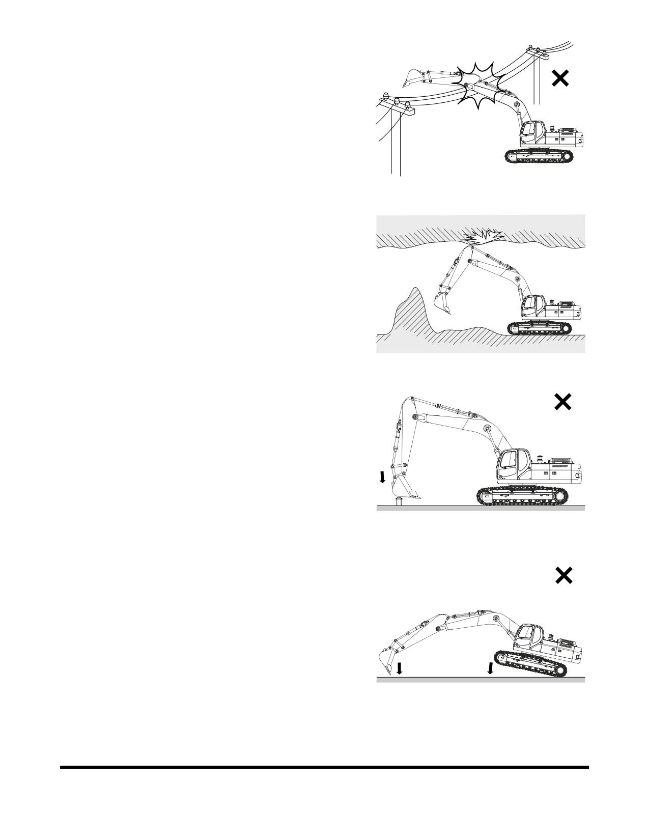
11. Make sure that there is adequate clearance from overhead
electrical supply lines. See Figure 64.
FG000171
Figure 64
12. If the excavation is in an underground location or in a
building, make sure that there is adequate overhead
clearance and that there is adequate ventilation. See
Figure 65.
FG000172
Figure 65
13. Do not use the bucket as a hammer or ramming device.
This is dangerous and causes damage to the front
attachment. See Figure 66.
FG000173
Figure 66
14. Do not dig with the excavator tracks raised. This can result
in structural and mechanical failures.
FG000174
Figure 67
OP000598
Operation
3-29
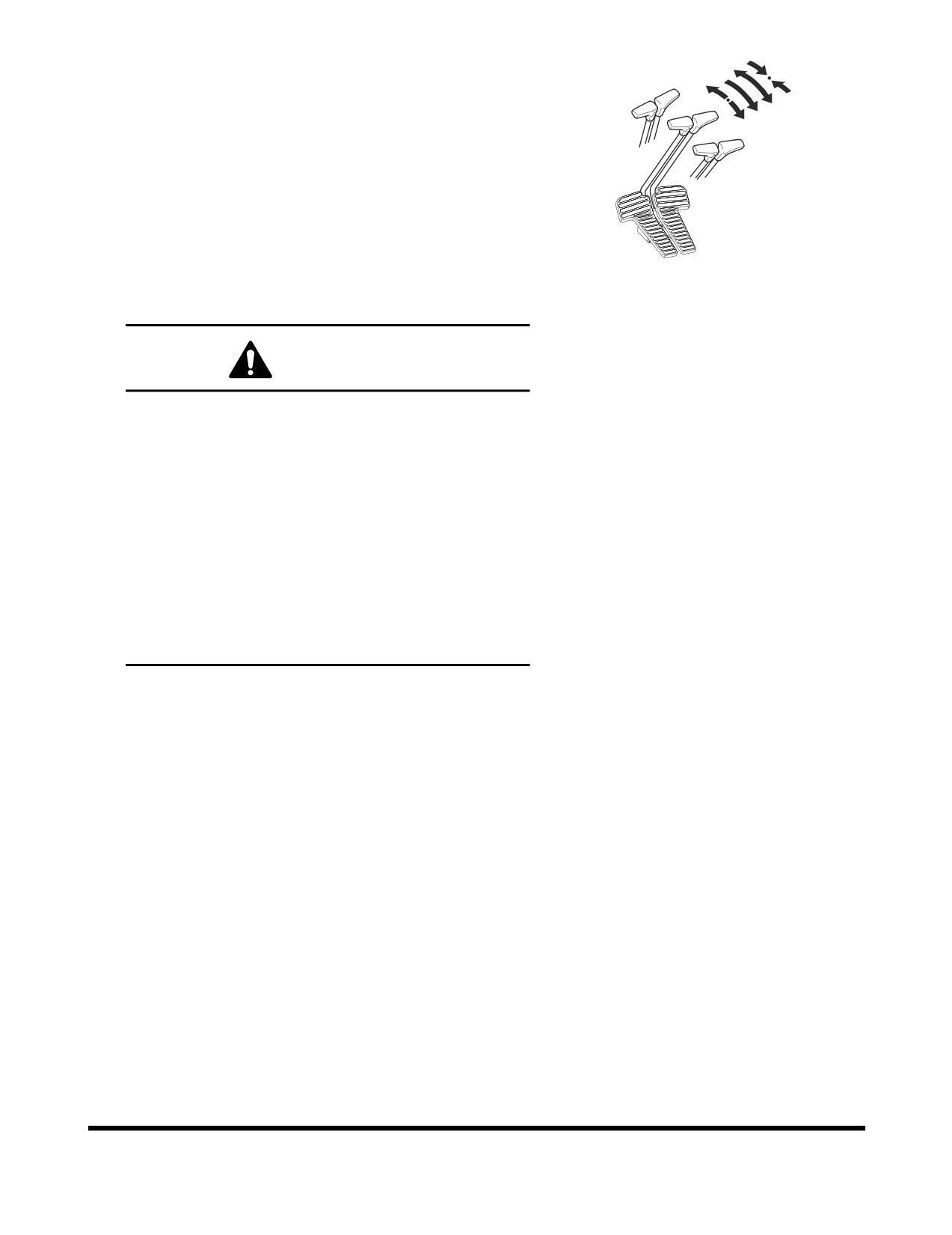
15. Do not operate travel lever quickly when traveling in high
range.
•
Avoid sudden starts.
•
When traveling in one direction come to a complete
stop before reversing directions. Do not rock
excavator back and forth with levers.
•
Avoid sudden stops. Return levers to neutral by
hand. Do not let them snap back to neutral on their
own.
FG000213
16. If the optional long fronts or attachments or heavy duty
Figure 68
front end attachments are used, the machine balance will
be altered. Follow these additional operating precautions.
WARNING!
Do not travel downhill with the front end attachments
raised.
Do not travel across slopes; travel straight up or down
slope.
Use extreme caution when swinging the upper frame
when positioned on a slope.
Allow extra swing stopping room. The additional
momentum generated by the longer or heavier front
end equipment will increase the amount of time
needed to stop the swing motion.
Make sure that all optional equipment has been
authorized and installed properly.
17. Do not move dirt or objects by swinging the excavator into
them. This can result in structural and mechanical failures.
Operation
OP000598
3-30
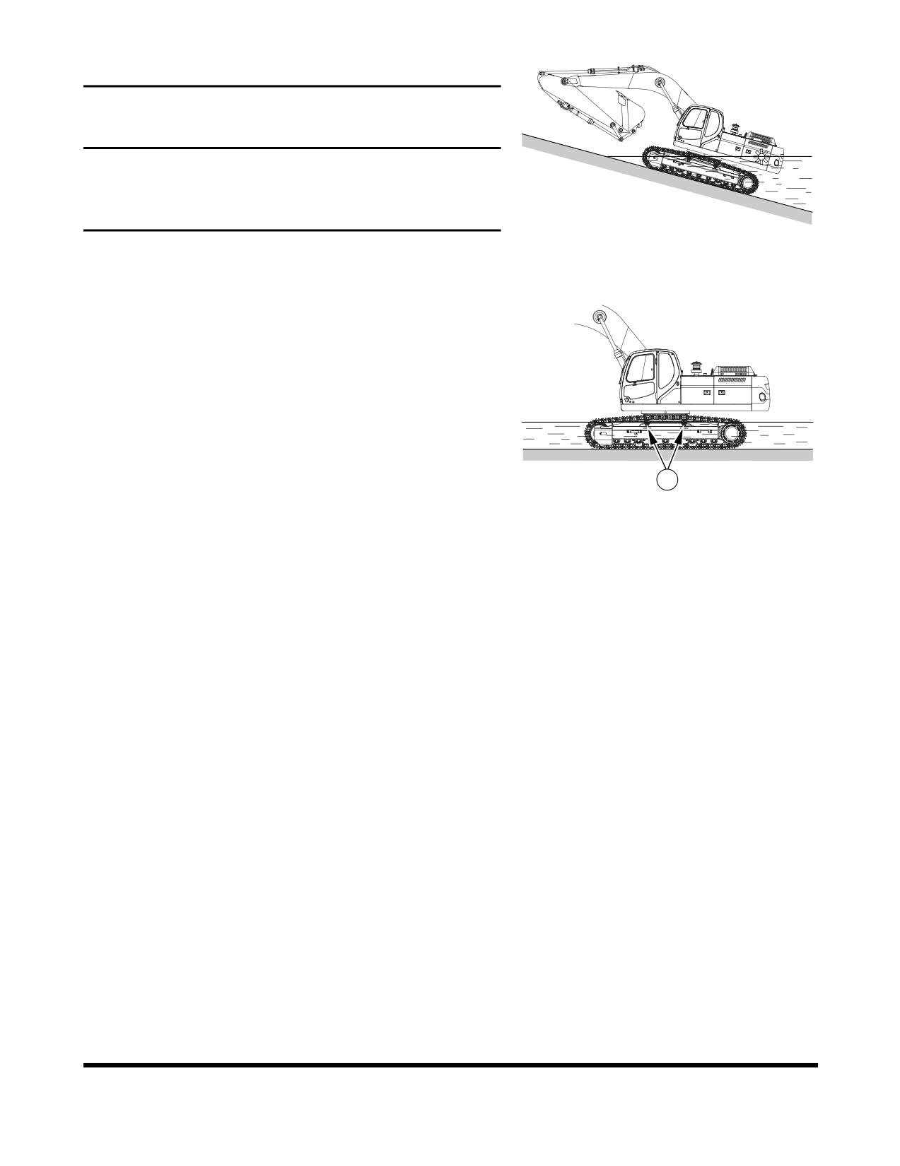
Working in Water
IMPORTANT
When working in water, do not exceed a slope of more than
15°. If the slope is over 15°, the rear part of the upper
structure will be immersed in water, resulting in radiator fan
and engine ECU damage.
FG000179
Figure 69
When working in water, do not operate in water over center of
upper roller (1, Figure 70).
If swing bearing gets wet, immediately grease it until all old
grease is purged from bearing.
If water gets into swing gear housing, drain water immediately
by removing lower inspection cover. Apply new grease.
After working in water, purge old grease on bucket pins.
1
FG000181
Figure 70
OP000598
Operation
3-31
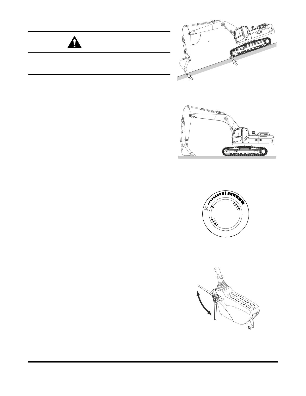
PARKING EXCAVATOR
WARNING!
120
Park excavator on firm, level ground. Avoid parking on
slopes. If excavator must be parked on a slope, block tracks
and place bucket teeth in ground. See Figure 71.
FG000214
Figure 71
1.
Park excavator on firm, level ground. Lower bucket to
ground as shown in Figure 72.
FG000111
Figure 72
2.
Set engine speed control dial on "LOW IDLE."
HAOB290L
Figure 73
3.
If you touch the operation lever unintentionally, it may
create a serious accident. Before leaving operator's seat,
set safety lever on "LOCK" position.
Unlock
lock
FG001091
Figure 74
Operation
OP000598
3-32
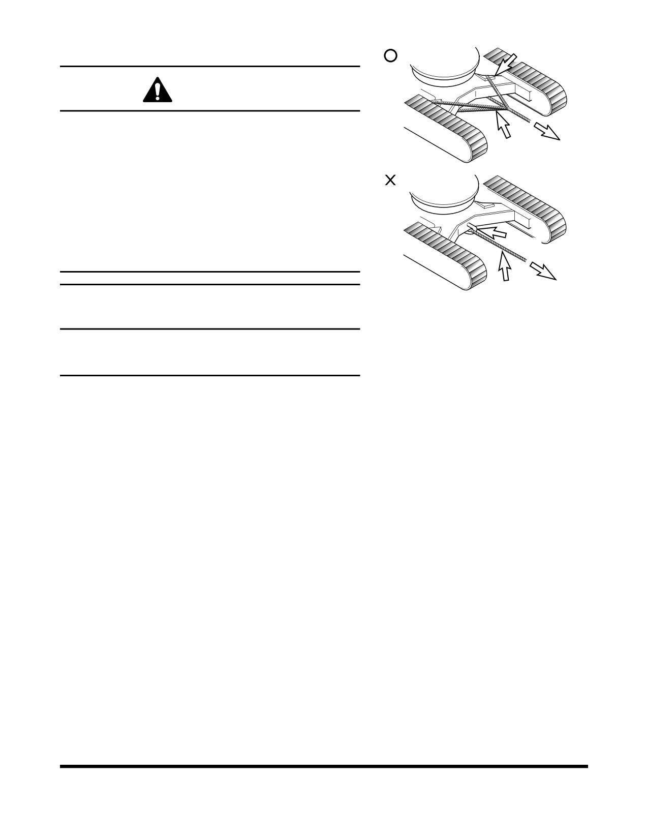
TOWING PROCEDURE
Cloth
WARNING!
Never use a damaged wire rope or chain. They could brake
and cause a serious accident.
Towing Wire
Always wear gloves when handling a chain or wire rope.
When towing excavator use a wire rope or chain capable of
handling the load.
Attach chain or wire rope to track frame as shown in Figure
75
Insert protective material such as thick cloths between
Shackle
track frame and wire rope to prevent the wire rope from
being damage.
Towing WireFG000669
Figure 75
IMPORTANT
Use shackle hook on track frame to only haul objects that
weigh less than 7 metric tons (7.71 U.S. Tons). Never use it
to haul objects over 7 metric tons (7.71 U.S. Tons).
OP000598
Operation
3-33
HYDRAULIC BREAKER
IMPORTANT
If a hydraulic breaker and piping is installed without
DOOSAN's authorization, it may create a serious
malfunction which will not be covered under the excavator
warranty.
Selection of Hydraulic Breaker
If a hydraulic breaker is installed, consider equipment's stability
and suitability for such modification. Also, consider hydraulic oil
pressure and quantity. When selecting a hydraulic breaker
consult with a DOOSAN distributor or sales agency.
Hydraulic Hoses and Tubing for Breaker
1.
When installing hydraulic breaker, assemble according to
drawings provided with kit.
2.
If breaker is taken off excavator, be sure to plug and cap all
hoses and tubing to prevent contamination from entering
hydraulic system.
3.
Plug and cap all connectors and fittings on breaker to
prevent contamination.
4.
Check all hydraulic connections for signs of leaks or loose
components before starting operation.
Hydraulic Breaker Operation
NOTE:
Hydraulic pressure and flow settings may need to be
changed. Refer to the Maintenance Section of this
manual for further information.
1.
Make sure to read and understand the breaker user's
manual.
2.
Inspect all mechanical and hydraulic connections.
Operation
OP000598
3-34
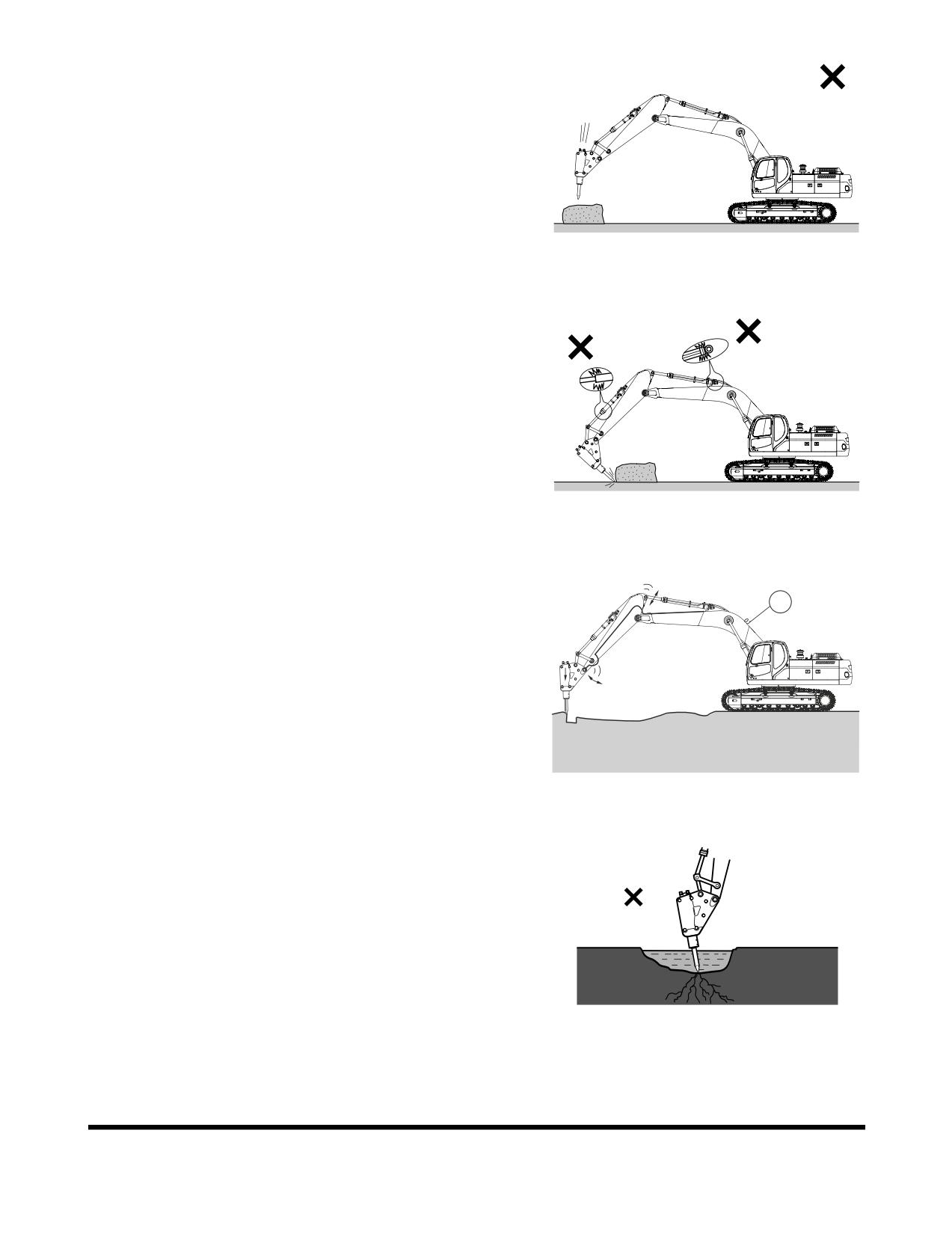
3.
Do not use the breaker as a hammer. See Figure 76.
Do not drop breaker from extreme heights.
The breaker is relatively heavy and drops fast. Do not drop
breaker from extreme heights or damage to upper
structure may result.
FG000188
Figure 76
4.
Do not operate the breaker with the boom or arm cylinders
fully extended (bottomed out). See Figure 77.
Leave over 100 mm (4 in) of clearance between rod end of
cylinder and cylinder head. This will help prevent damage
to cylinders during breaker operation.
FG000191
Figure 77
5.
Do not use the breaker if the hydraulic hoses vibrate
excessively. See Figure 78. Check the breaker's hydraulic
1
accumulator (1) for damage and repair as required. If
excavator is operated under this condition, structural and
hydraulic components can be damaged.
FG000215
Figure 78
6.
Do not allow the breaker body to go into water if not
equipped for underwater operation. The breaker seal can
be damaged and allow rust, foreign material or water to
enter the hydraulic system and cause damage. Only insert
the breaker tool into water. See Figure 79.
HAOB970L
Figure 79
OP000598
Operation
3-35
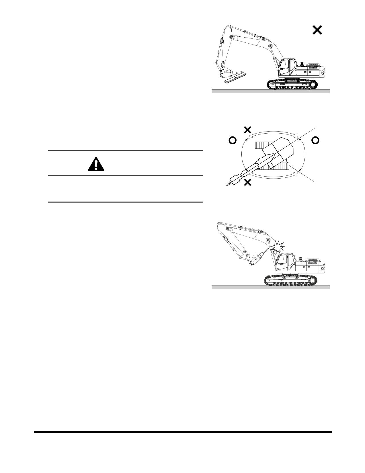
7.
Do not any lifting or towing with a breaker. See Figure 80.
FG000207
Figure 80
8.
Operate the breaker only to the front and rear of the
excavator. Do not use the breaker to either side of the
excavator. Do not swing the breaker from side to side
when operating it. See Figure 81.
WARNING!
Operating a breaker with the upper body turned 90° to
the tracks can result in tipping over the machine or
reduction in service life.
HAOB990L
Figure 81
9.
Do not curl the breaker tool tip into the arm or boom when
traveling or parking the excavator. See Figure 82.
FG000216
Figure 82
Operation
OP000598
3-36
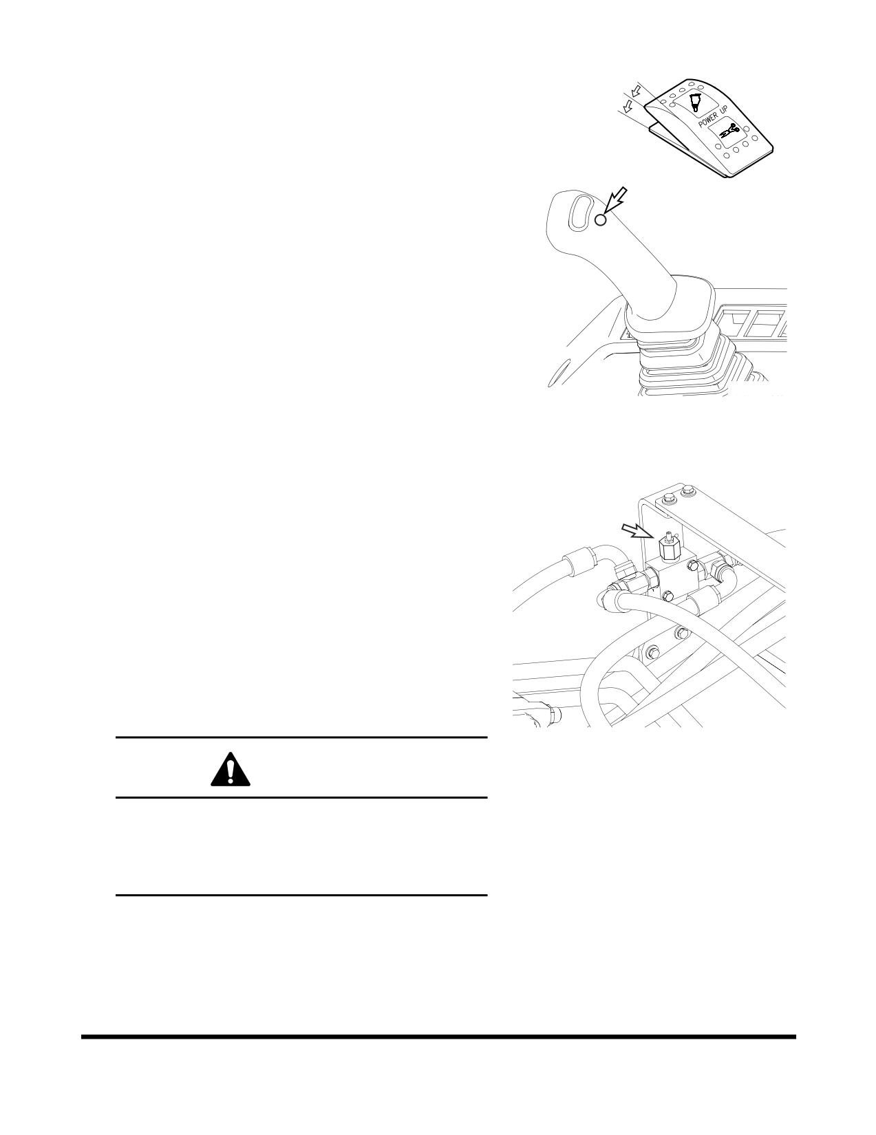
To activate breaker
I
1.
Set breaker selector switch to "II" (BREAKER) position.
O
2.
Press lower button on top of right-hand work lever
I
(joystick) to activate hydraulic breaker.
3.
Release lower button on top of right-hand work lever
(joystick) to deactivate hydraulic breaker.
FG000117
Figure 83 RIGHT-HAND WORK LEVER
(JOYSTICK)
Relief Valve Adjustment
1.
Cap pipe on arm end, using a cap capable of handling
350.0 kg/cm2
(5,000 psi) under the condition of
disconnecting hose to hydraulic breaker.
2.
Adjust pump pressure using activating the breaker, and
watching the pressure displayed on the instrument panel.
Press the display selector button to show digital pressure
reading. (A separate pressure gauge is not required.)
3.
Adjust the relief valve pressure by turning the adjustment
screw of breaker relief valve. The relief valve is installed on
the left side of the upper structure behind the boom. (Do
not use the overload relief valve on the lower part of control
valve for the breaker relief valve.)
FG000777
Figure 84
WARNING!
If the relief valve pressure is adjusted while the
hydraulic breaker is connected, there is possibility
that a high-pressure spike or setting could break a
hose or pipe. Personal injury or death could result
from a hydraulic hose or pipe failure.
OP000598
Operation
3-37
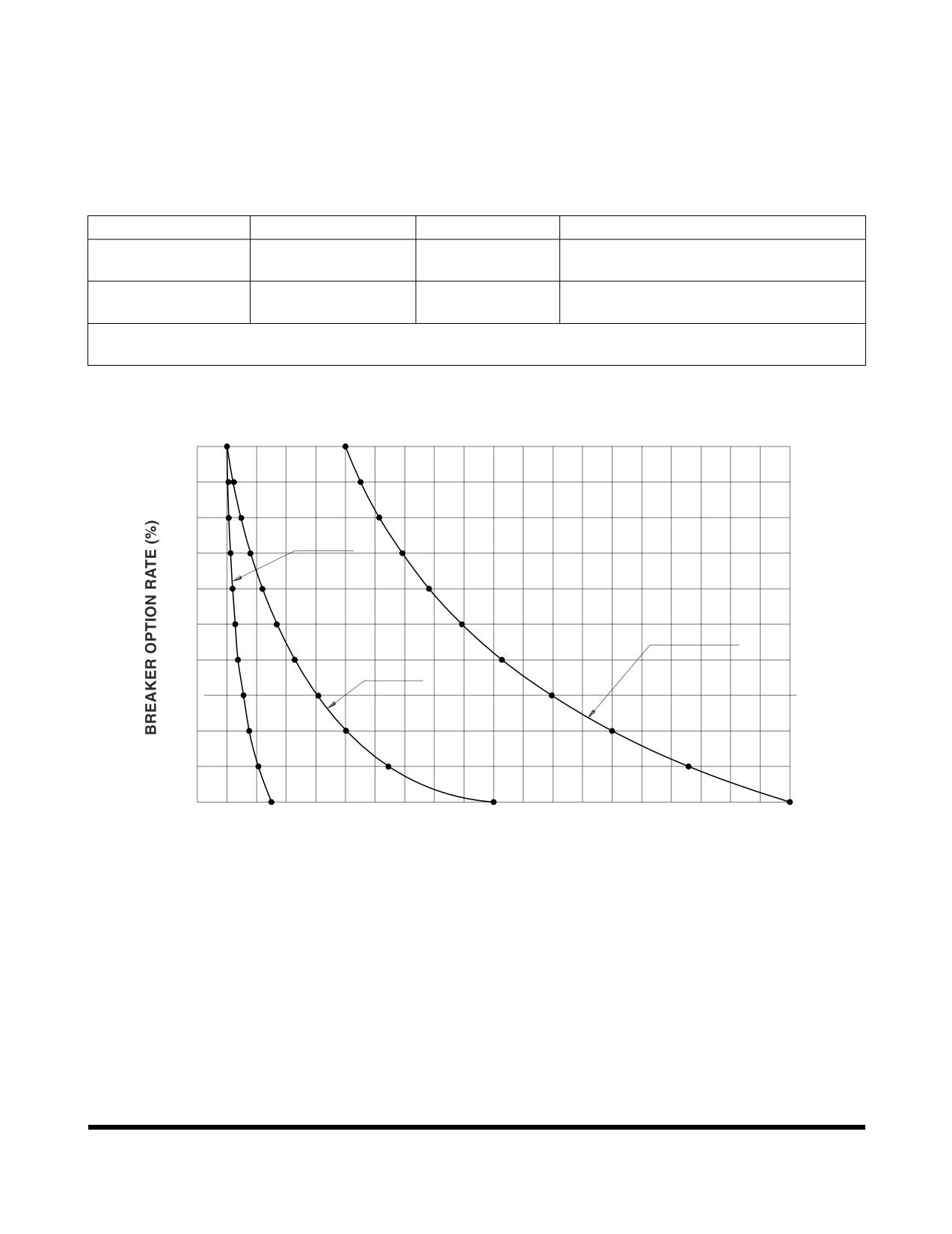
Hydraulic Oil and Filter Service Intervals
When using a hydraulic breaker, the viscosity breakdown and
contamination of hydraulic oil is faster because the work
condition is more severe than during normal digging work. To
prevent the hydraulic components (especially pump) from
having a shortened life cycle, replace the hydraulic oil and main
hydraulic oil return filter using the following schedule.
Attachment
Operation Rate
Hydraulic Oil
Filter
250 Hours (First Replacement)
Bucket Work
100%
2,000 Hours
1,000 Hours (After First Replacement)
Hydraulic Breaker
100%
500 Hours
100 Hours
Work
*
These service intervals only apply, when a genuine DOOSAN oil and filter are used. If any other
brands are used, the guaranteed changed interval should be reduced in half.
100
105
116
551
106
14
4
614
80
FILT
ER
692
112
171
(Firs
t Rep
lacement)
119
214
782
60
128
275
893
HYDRAU
LIC OIL
137
335
1028
40
FILTER
15
6
412
(A
fter F
irst Replacemen
t)
1196
175
500
1400
20
206
63
5
1658
0
500
1000
1500
2000
MACHINE OPERATING HOURS
FG000767
Figure 85
NOTE:
The replacement intervals of hydraulic oil and filter
depend upon the amount of time the hydraulic
breaker is being used. These intervals should be
followed as opposed to regularly scheduled
maintenance.
Operation
OP000598
3-38
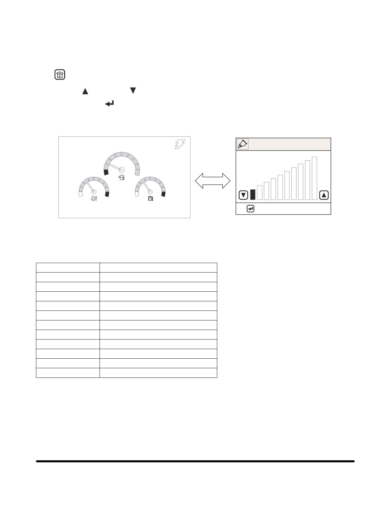
ADJUSTING THE PUMP FLOW
NOTE:
For further information, see “Flow Control” on
page 2-47.
1.
On the instrument panel, press the flow control button
, the flow control screen (Figure 86) will be displayed.
2.
Use "UP" (
) or "DOWN" (
) buttons to adjust flow rate.
3.
Press "SELECT" (
) button, to return to normal display
screen and save the flow rate setting.
02/05 [MO] 11:30
FLOW CONTROL
E
F
C
H
C
H
: APPLY
ESC: CANCEL
E/G SPEED 1700 RPM
<Normal Display>
<Flow Control Display>
FG001090
Figure 86
Setting
Flow Rate (l/min)
0
48.5
1
57
2
66
3
69
4
78.5
5
90
6
96.5
7
106.5
8
108
9
114
10
114
OP000598
Operation
3-39
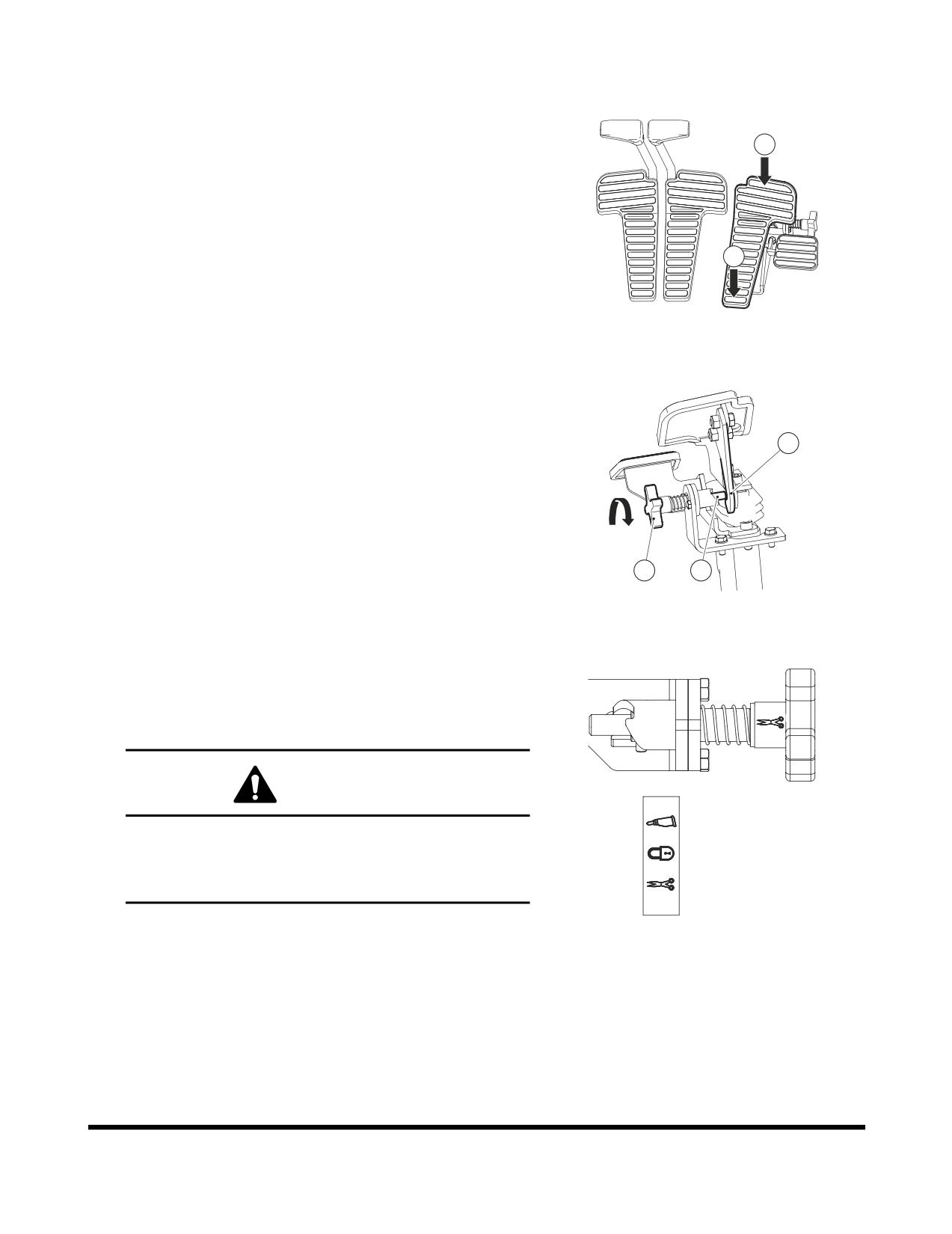
Shear Pedal Valve (Optional)
Activating Shear with Pedal Valve
1.
Select shear with the selector switch of the right panel.
1
2.
Two-way operation is possible by rocking the pedal back
and forth between positions (1 and 2, Figure 87). When the
pedal is in its center (at rest) position the valve is in
"NEUTRAL" and hydraulic oil flow is stopped.
3.
Before operating the attachment, be sure to check the
2
function controlled by the direction of the pedal movement.
FG000402
Figure 87
Activating Breaker with Pedal Valve
1.
Select breaker with the selector switch of the right panel.
2.
Rotate knob (3, Figure 88) 120° for stopper (4, Figure 88)
5
be fastened to (5, Figure 88).
3.
In the condition that (2, Figure 88) is fastened, activate the
breaker to the direction (1, Figure 88).
3
4
FG000403
Figure 88
Adjusting the Stopper
1.
Rotate knob (3, Figure 88) in the direction of the arrow.
then the pedal is activated according to the display caused
by (3, Figure 88) knob rotation.
CAUTION!
Breaker
When operating breaker or shear when using button
on a joystick, and it is not to be controlled by the
Lock
pedal, be sure to keep the stopper in the "LOCK"
position in order for the pedal not to be activated.
Shear
FG000434
Figure 89
Operation
OP000598
3-40
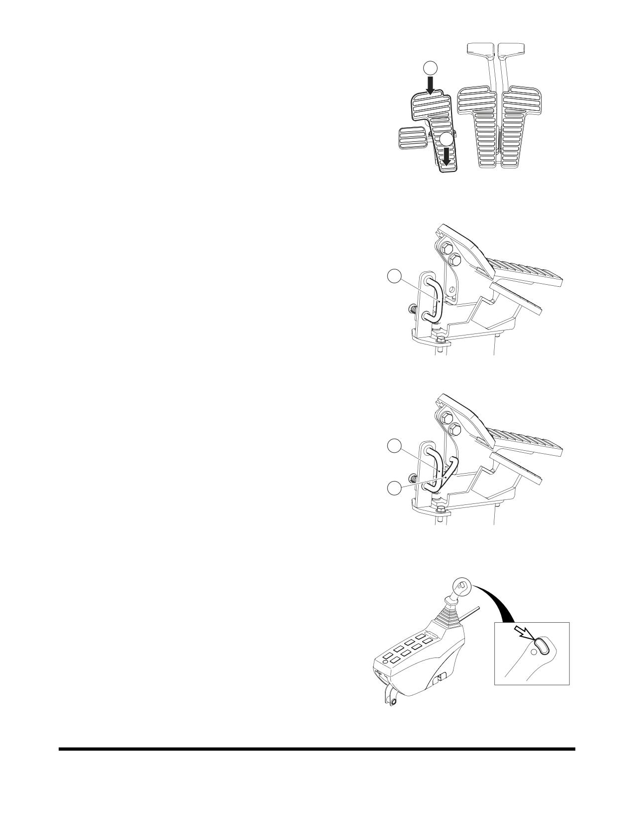
Rotating Pedal Valve (Optional)
1
Attachment Rotating by Using the Pedal Valve
1.
Pressing end (1, Figure 90) is used to turn clockwise.
2.
Pressing end
(2, Figure
90) is used to turn
counterclockwise.
2
NOTE:
Before activating the pedal, be sure to check
the function of the attachment.
FG000405
Figure 90
Locking the Pedal
When rotating is not needed, the pedal can be locked by using
the prop rod (3) locking device.
Locking is completed when the top end of the prop (3) is
3
positioned into pedal hole.
FG000406
Figure 91
A.
Location for "UNLOCKING."
B,
Location for "LOCKING."
A
B
FG000407
Figure 92
Attachment Rotation Using the Left-hand Work Lever
(Joystick)
For a machine equipped with an attachment that rotates,
rotation is activated while one of the control buttons is being
pressed on top of the left-hand work lever (joystick).
There are three buttons on top of the left-hand work lever. The
left and right ones are for controlling rotation.
NOTE:The middle button is for the horn.
Left button is for counterclockwise rotation, and the right one is
FG000035
for clockwise rotation.
Figure 93 LEFT-HAND WORK LEVER
(JOYSTICK)
OP000598
Operation
3-41
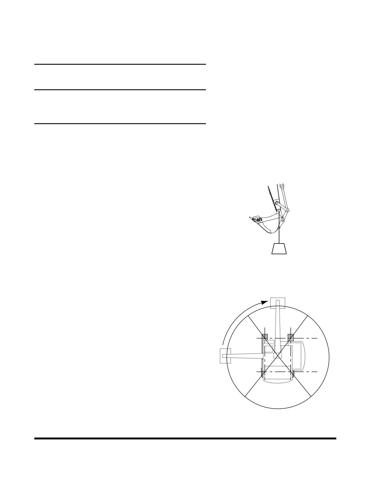
OPERATING TECHNIQUES
Lifting
IMPORTANT
There may be local or government regulations, about the
use of excavators for the lifting of heavy loads. Always
contact your local and government agencies in regards to
these regulations.
To prevent injury, do not exceed the rated load capacity of the
machine. If the machine is not on level ground, load capacities
will vary.
Short slings will prevent excessive load swing.
Use the lifting eye on the bucket that is provided to lift objects.
Always try to maintain the lifting eye (Figure 94) straight below
the center line of the arm and bucket pin. In this manner the
weight of the load is being primarily held only by the pin, and not
by the bucket cylinder, link, and link pins.
When a lifting eye is used, the sling/lifting device must be
fastened to the eye in a manner that will not allow it to come
loose.
The most stable position is over the corner of the machine.
For best stability, carry a load as close to the ground and
machine as possible.
HAAD3830
Figure 94
Lift capacity decreases as the distance from the machine swing
center line is increased.
Lifting Unknown Weight
When loads are not accurately known are to be lifted, the person
responsible for the job shall ascertain that the weight of the load
FRON
T LIFT
does not exceed the machine LOAD RATING CHART at the
ZO
N
E
radius at which it is to be lifted.
It is recommended that you feel your way into any lift as a
precaution against tip-over. One method is to position the boom
at 90° over the side of the machine. Slowly lift the load until it
SIDE LIFT
SIDE LIFT
ZONE
ZONE
clears the ground. A lift over the side is the most unstable, and
as the load is swung into the front zone of the excavator it will
become more stable. DO NOT INCREASE SWING RADIUS
AFTER THE LOAD IS LIFTED.
REAR LIFT
ZONE
HAAD3842
Figure 95
Operation
OP000598
3-42
DANGER!
If a load is picked up from the front zone and swung into the
side zone, a tip-over could result causing a deadly or fatal
injury.
Lifting Known Weight
The load chart is the governing factor when lifting known
weights. It is recommended that you feel your way into any lift as
a precaution against tip-over. Whenever possible, lift and swing
payloads between the front idler area.
Pick and Carry
The machine has the ability to pick and carry payloads without
added labor. We recommend when traveling with a suspended
payload, you evaluate the prevailing conditions and determine
the safety precautions required in each case. The following
factors must be considered before attempting to pick and carry a
load.
Align the boom with the forward direction of machine travel.
Maintain this boom position when turning the machine. Turn only
when necessary, at the slowest speed, and at a wide turning
radius.
1.
Use the shortest lifting radius distance possible.
2.
Keep the load as close to the ground as conditions will
permit.
3.
Provide tag lines to prevent load from pendulating.
Pendulating can cause a change in radius. A change in
radius could exceed the load chart rating or cause a
tip-over condition.
4.
Govern travel speed to suit conditions.
5.
Avoid sudden starts and stops.
OP000598
Operation
3-43
OPERATION UNDER UNUSUAL
CONDITIONS
NOTE:
See “Maintenance in Special Conditions” on
page 4-88 for other recommendations.
Operation In Extreme Cold
If machine is to be operated in extreme cold weather
temperatures, certain precautions must be taken to assure
continued normal operation. The following paragraphs detail
checks to be made to be certain the machine is capable of
operating at these temperatures.
1.
Check the cooling system for correct antifreeze solution for
lowest temperature expected. Carefully inspect cooling
system and correct or report any leaks.
2.
Keep batteries fully charged to prevent freezing. If water is
added to batteries, run engine at least one hour to mix
electrolyte solution.
3.
Keep engine in best possible mechanical condition to
assure easy starting and good performance during
adverse weather conditions.
4.
Use engine oil of the proper specifications for the expected
temperatures. Refer to the "Lubrication Specifications" of
the engine manual for details.
5.
Keep fuel tank full at all times. Drain condensation from
tank before and after operation. Drain and service fuel
filter. To eliminate clogging of fuel filters due to wax crystal
formation in the fuel, be sure that the fuel used has a cloud
point specification below the lowest expected temperature.
6.
Lubricate entire machine according to "Periodic Service
Table and Chart" Section 4, in this manual or lubrication
chart on machine.
7.
Start engine and allow it to reach normal operating
temperature before applying load.
A.
If mud and ice collects and freezes on any of the
moving parts while machine is idle, apply heat to
thaw the frozen material before attempting to operate
machine.
B.
Operate hydraulic units with care until they have
reached a temperature to enable them to operate
normally.
C.
Check all machine controls and/or functions to be
sure they are operating correctly.
8.
An extra outer air filter should be kept in the operator's
cabin to replace element that could become iced and
cause restricted air flow to engine.
Operation
OP000598
3-44
9.
If cold weather starting aid must be used, see "Engine
Starting" COLD WEATHER START portion of this manual.
10. Clean off all mud, snow and ice to prevent freezing. Cover
machine with tarpaulin if possible, keep ends of tarpaulin
from freezing to ground.
Operation in Extreme Heat
Continuous operation of the machine in high temperatures may
cause the machine to overheat. Monitor engine and
transmission temperatures and stop machine for a cooling-off
period whenever necessary.
1.
Make frequent inspections and services of the fan and
radiator. Check coolant level in radiator. Check grills and
radiator fins for accumulation of dust, sand and insects
which could block the cooling passages.
A.
Formation of scale and rust in cooling system occurs
more rapidly in extremely high temperatures. Change
antifreeze each year to keep corrosion inhibitor at full
strength.
B.
If necessary, flush cooling system periodically to
keep passage clear. Avoid use of water with a high
alkali content which increases scale and rust
formation.
2.
Check level of battery electrolyte daily. Keep electrolyte
above plates preventing damage to batteries. Use a
slightly weaker electrolyte solution in hot climates. Dilute
1.28 specific gravity electrolyte as issued to 1.20 - 1.24
specific gravity readings at full charge. Recharge batteries
whenever they reach a
1.16 specific gravity reading.
Batteries self-discharge at a higher rate if left standing for
long periods at high temperatures. If machine is to stand
for several days, remove batteries and store in a cool
place.
WARNING!
Do not store acid type storage batteries near stacks of
tires; the acid fumes have a harmful affect on rubber.
3.
Service fuel system as directed in "Engine Fuel System"
Section 5, of this manual. Check for water content before
filling fuel tank. High temperatures and cooling off cause
condensation in storage drums.
4.
Lubricate as specified in "Periodic Service Chart and
Table" Section 4, in this manual or Lubrication Decal on
the machine.
5.
Do not park machine in sun for long periods of time. When
practical park machine under cover to protect it from sun,
dirt and dust.
OP000598
Operation
3-45
A.
Cover inactive machine with tarpaulin if no suitable
shelter is available. Protect engine compartment,
transmission and hydraulics from entrance of dust.
B.
In hot, damp, climates corrosive action will occur on
all parts of the machine and will be accelerated
during the rainy season. Rust and paint blisters will
appear on metal surfaces and fungus growth on other
surfaces.
C.
Protect all unfinished, exposed surfaces with a film of
preservative lubricating oil. Protect cables and
terminals with ignition insulation compound. Apply
paint or suitable rust preventive to damaged surfaces
to protect them from rust and corrosion.
Operation in Dusty or Sandy Areas
Operation of the machine can cause dust in almost any area.
However, when in predominantly dusty or sandy areas,
additional precautions must be taken.
1.
Keep cooling system fins and cooling areas clean. Blow
out with compressed air, if possible, as often as necessary.
WARNING!
Wear goggles when using compressed air.
2.
Use care when servicing fuel system to prevent dust and
sand from entering the tank.
3.
Service the air cleaner at frequent intervals, check air
restriction indicator daily and keep dust cup and dust valve
clean. Prevent dust and sand from entering engine parts
and compartments as much as possible.
4.
Lubricate and perform services outlined on current
lubrication chart on machine and "Lubrication Chart and
Table" Section
4. Clean all lubrication fittings before
applying lubricant. Sand mixed with lubricant becomes
very abrasive and speeds wear on parts.
5.
Protect machine from dust and sand as much as possible.
Park machine under cover or protect with tarpaulin to keep
dust and sand from damaging unit.
Operation in Rainy or Humid Conditions
Operation under rainy conditions is similar to that as in extreme
heat procedures listed previously.
1.
Keep all exposed surfaces coated with preservative
lubricating oil. Pay particular attention to damaged or
unpainted surfaces. Cover all paint cracks and chip marks
as soon as possible to prevent corrosive effects.
Operation
OP000598
3-46
Operation in Salt Water Areas
The corrosive effect of salt water and salt water spray is very
extensive. When operating in salt water areas, observe the
following precautions.
1.
When exposed to salt water, dry machine thoroughly and
rinse with fresh water as soon as possible.
2.
Keep all exposed surfaces coated with preservative
lubricating oil. Pay particular attention to damaged paint
surfaces.
3.
Keep all painted surfaces in good repair.
4.
Lubricate machine as prescribed on lubrication chart on
machine or "Periodic Service Table and Chart" Section 4,
in this manual. Shorten lubricating intervals for parts
subject to exposure to salt water, if found necessary.
Operation at High Altitudes
Normally, operation of machine at high altitudes will be as
outlined in extreme cold. Before operating at high altitudes,
engine fuel and air mixture may have to be adjusted according
to appropriate engine manual.
1.
Check engine operating temperature for evidence of
overheating. The pressure cap on radiator must make a
perfect seal to maintain coolant pressure in the system.
OP000598
Operation
3-47
Operation
OP000598
3-48
OP000599
4Inspection, Maintenance
and Adjustment
PREVENTIVE MAINTENANCE
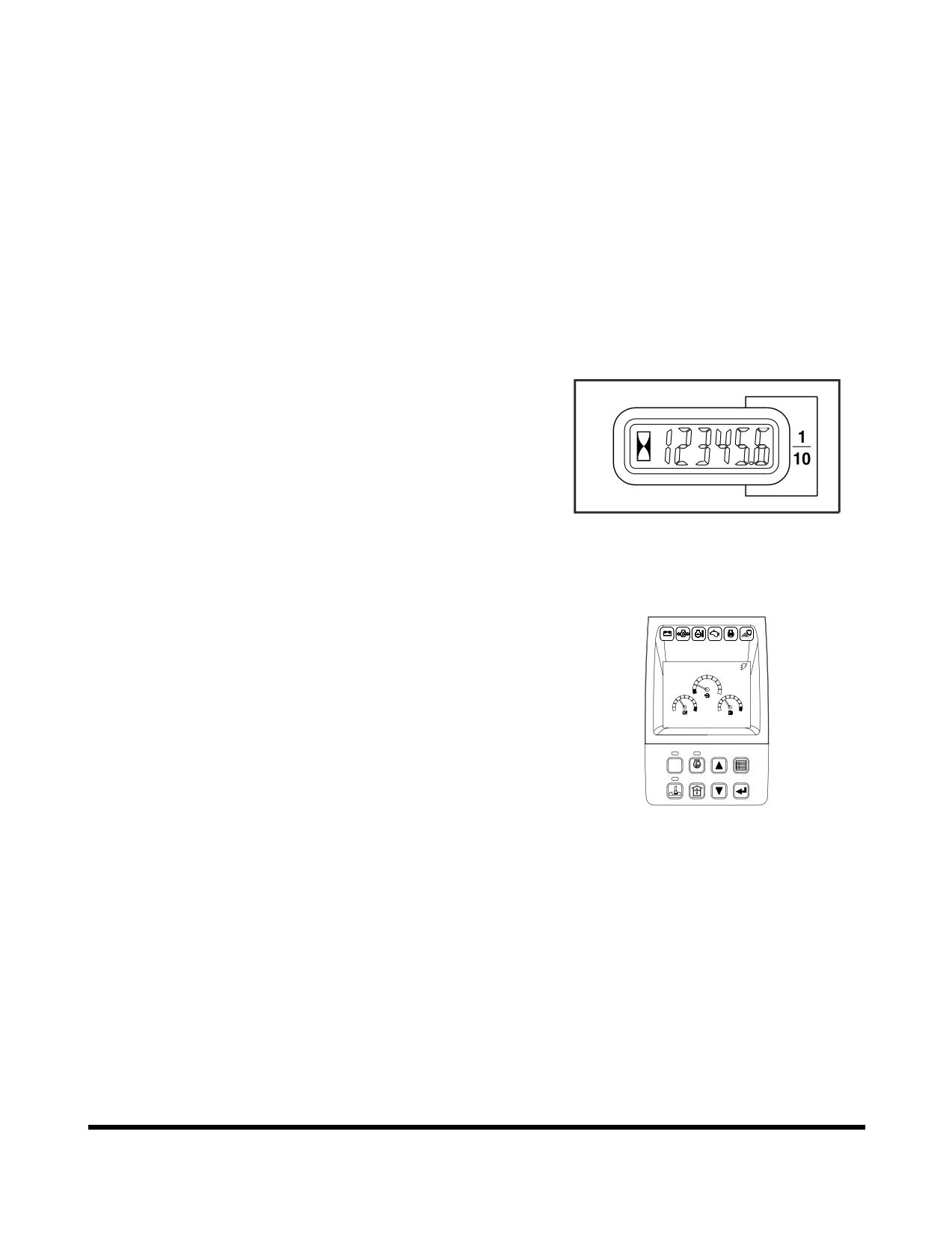
Routine maintenance and inspections are required to keep your
machine in the correct operating condition. The following pages
list the inspection intervals, the system or component checks,
and location references.
NOTE:
The following pages list the service checks and their
required intervals. The service cycles may need to be
shortened depending on the working conditions.
Extremely hot or dusty conditions will require more
frequent service. Operational hours are determined
by the amount of time accumulated on the engine
hour meter on the control console in the cabin.
HAOA601L
Figure 1
NOTE:
Besides the normal hour meter, the multifunction
gauge can be used to keep track of the hours on
CHECK
individual filters. See “Filter / Oil Info” on page 2-42.
02/05 [MO] 11:30
E
F
C
H
C
H
E/G SPEED
1700
RPM
POWER
AUTO
1
2
3
4
ESC
5
6
7
8
FG000037
Figure 2
OP000599
Inspection, Maintenance and Adjustment
4-1
Product Identification Number (P. I. N.)
Location
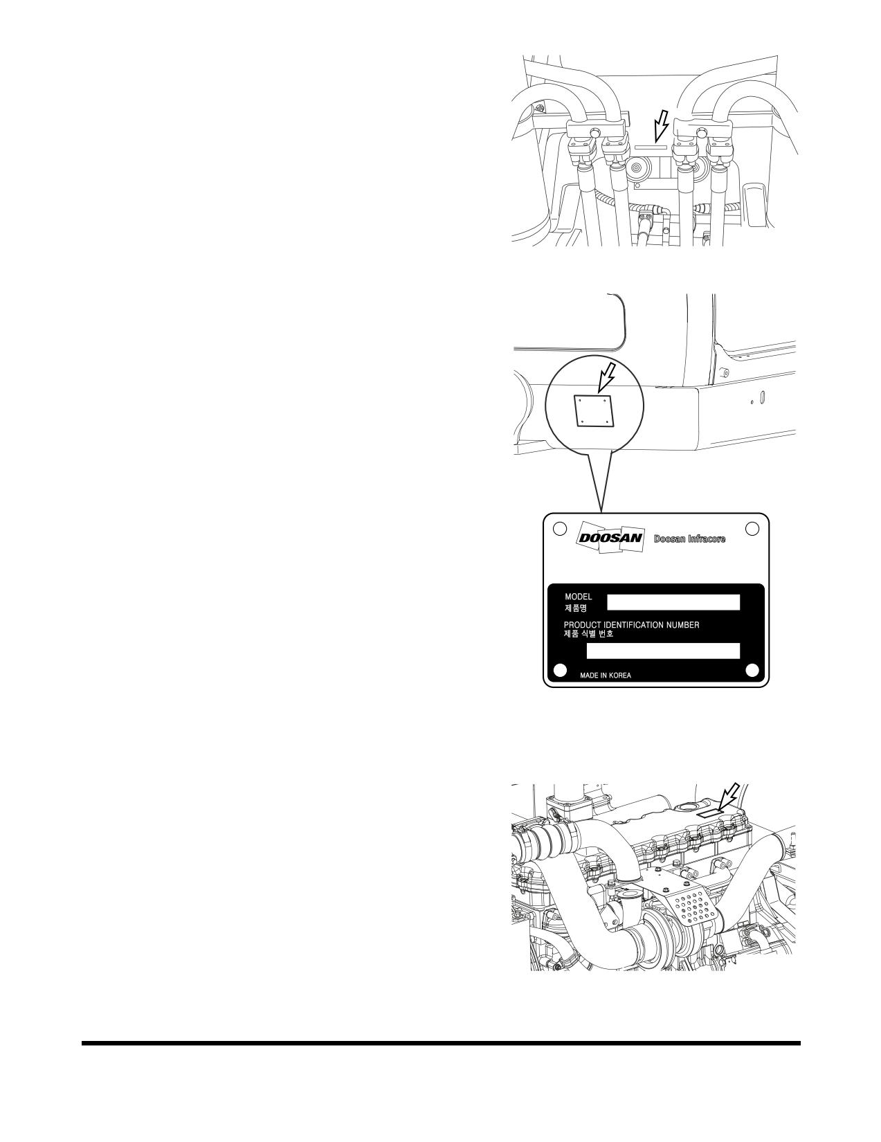
A P.I.N. number, is stamped on the upper frame, under the
boom foot (Figure
3). It is also stamped on the product
identification plate (Figure 4) on outside of the cabin on right.
NOTE:
Please make note of these numbers and their
locations. These will be required whenever warranty
or service work is requested. Keep this number on
file, incase the machine is stolen.
FG001447
Figure 3
7-11, Hwasu-dong, Dong-gu,
Incheon, Korea
K1011647B
FG009600
Figure 4
Component Serial Numbers
There are many serial numbers on each traceable components
of the machine. For example, the engine serial number is
stamped on the rear left side of the engine block, above the
starter. Additional engine information is described on a label
(Figure 5) on the rocker cover.
Please make note of these numbers and their locations. These
will be required whenever warranty service work is requested.
FG006402
Figure 5
Inspection, Maintenance and Adjustment
OP000599
4-2
Safety Precautions
1.
Make sure to lock out the hydraulic controls and post a
notice (Warning Tag) that the machine is being serviced to
prevent any unauthorized operation.
2.
Make sure to clean up any fluid spills, especially around
the engine.
3.
Inspect all fuel lines to make sure that fittings, lines, filters
and O-rings, etc., are tight and are not showing signs of
wear or damage.
4.
If the inspection or test procedure requires that the engine
be running, make sure to keep all unauthorized personnel
away from the machine, and that all industry standard
safety precautions are followed.
OP000599
Inspection, Maintenance and Adjustment
4-3
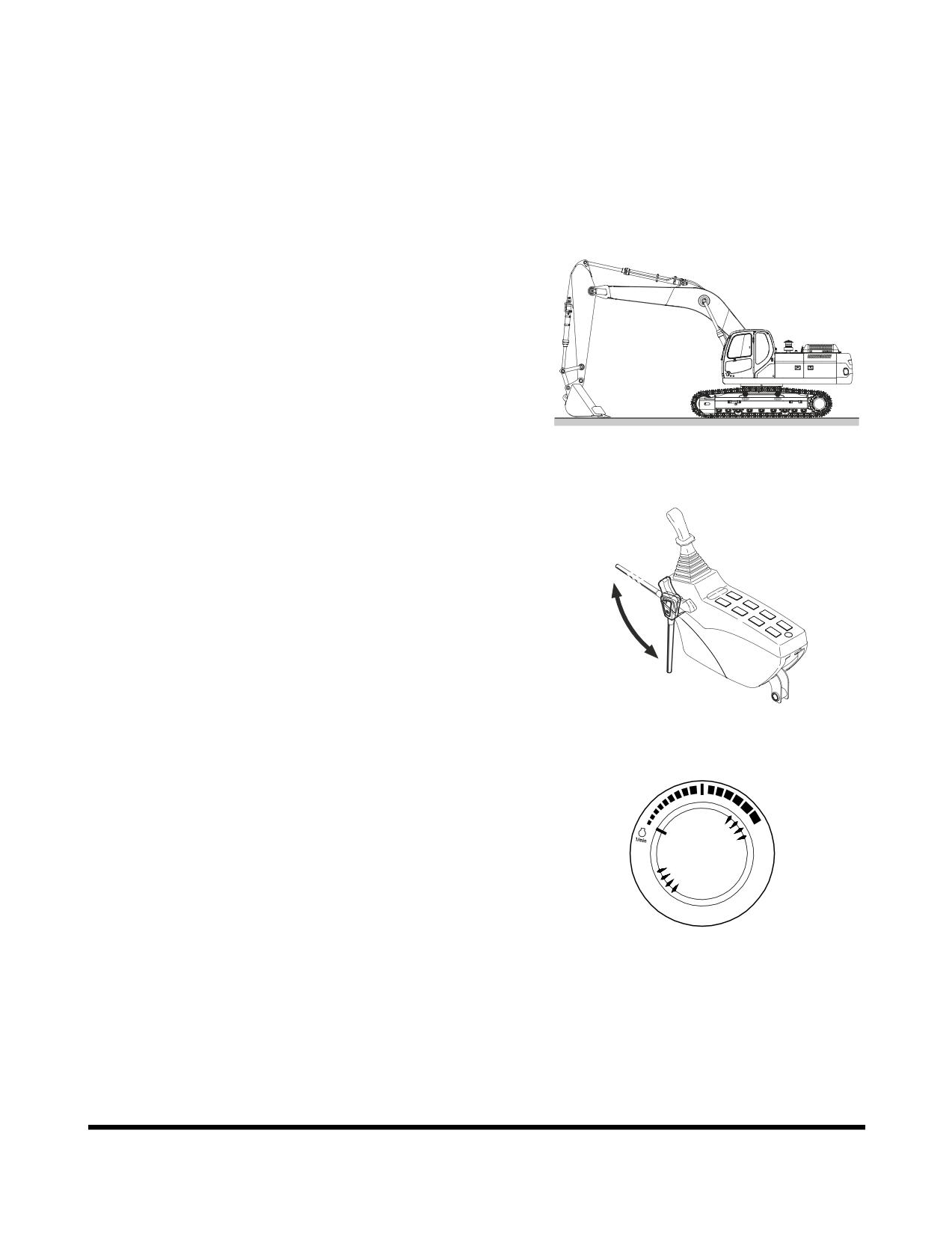
PRELIMINARY WORK MACHINE
SETUP FOR MAINTENANCE
When performing maintenance specified in this manual, always
park the excavator as follows.
NOTE:
Certain types of maintenance may require the
machine to be positioned differently. Always return
machine to this position.
1.
Park on firm, level ground.
2.
Lower bucket to ground.
FG000111
Figure 6
3.
Set safety lever on "LOCK" position.
Unlock
lock
FG001091
Figure 7
4.
Allow engine to run at low idle for a minimum of five
minutes to allow engine to cool. If this is not done, heat
surge may occur.
HAOB290L
Figure 8
Inspection, Maintenance and Adjustment
OP000599
4-4
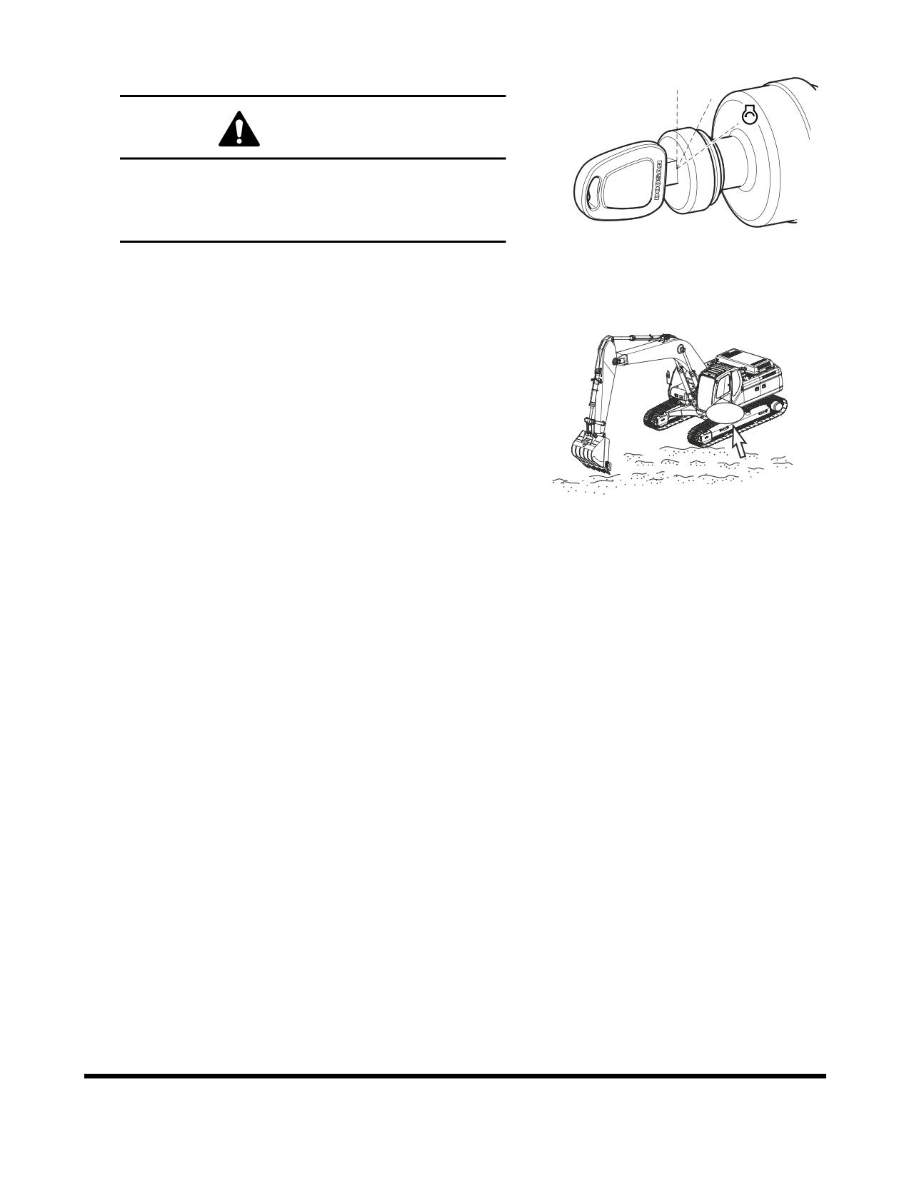
5.
Shut down engine by turning key to "O" (OFF) position.
Remove key from starter switch.
O I
WARNING!
If engine must be run while performing maintenance,
use extreme care. Always have one person in the
cabin at all times. Never leave the cabin with the
engine running.
FG000175
Figure 9
6.
Before starting maintenance work, hang up a tag, "Do Not
Touch When Performing Inspection or Maintenance" on
cabin door or work lever.
FG000401
Figure 10
OP000599
Inspection, Maintenance and Adjustment
4-5
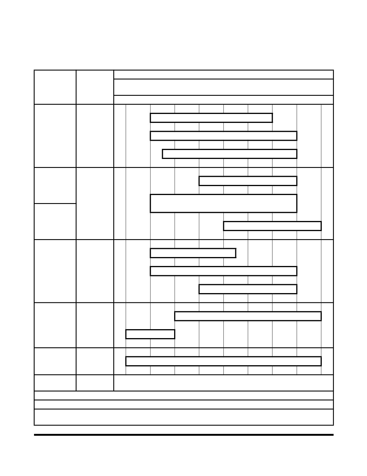
TABLE OF RECOMMENDED
LUBRICANTS
NOTE:
Refer to the Maintenance Intervals Table for
application points.
Ambient Temperature
Kind of
-22
-4
14
32
50
68
86
104
122
Reservoir
Fluid
°F
-30
-20
-10
0
10
20
30
40
50 °C
SAE 10W-30
Engine Oil
**
* SAE 10W-40
Pan
Engine Oil
SAE 15W-40
Swing Drive
SAE 90 and API GL5
Case
Gear Oil
* SAE 80W-90 and API GL5
Final Drive
Case
SAE 140 and API GL5
ISO VG 32
***
Hydraulic Oil
Hydraulic
* ISO VG 46
Tank
Oil
ISO VG 68
* ASTM D975 No. 2
Fuel Tank
Diesel Fuel
ASTM D975 No. 1
Grease
Grease
* Multipurpose Lithium Grease NLGI No. 2
Fitting
Cooling
Add Antifreeze
Coolant
System
* (50% antifreeze - 50% distilled water)
*
Installed at factory.
**
Engine oil must meet ACEA-E5 or API-CI-4.
*** Hydraulic oil change interval is 2,000 hours, only when DOOSAN Genuine Oil is used. If other brands of
oil is used, guaranteed change interval is 1,000 hours.
Inspection, Maintenance and Adjustment
OP000599
4-6
API: American Petroleum Institute.
ACEA: Association des Constructeurs Europens d’Automobiles.
ASTM: American Society of Testing and Material.
ISO: International Standardization Organization.
NLGI: National Lubricating Grease Institute.
SAE: Society of Automotive Engineers.
IMPORTANT
Do not mix oils from different manufacturers. DOOSAN
does not endorse specific brands but does suggest that
owners select quality oils whose suppliers provide
assurance that required standards will always be met or
exceeded.
Fluctuating daily or weekly extremes of temperature, or
operation in subzero freezing weather may make it
impractical to use straight weight lubricants. Use good
judgement in selecting lubricant types that are appropriate
for climate conditions.
OP000599
Inspection, Maintenance and Adjustment
4-7
FLUID CAPACITIES
Component
Capacity
Engine
Oil Pan with Filter
22 liters
(5.8 U.S. gal.)
Cooling System
20 liters
(5.3 U.S. gal.)
Fuel Tank
267 liters
(70.5 U.S. gal.)
Hydraulic Oil
Tank Level
98.8 liters
(26.1 U.S. gal.)
System
147.8 liters
(39.0 U.S. gal.)
Travel Reduction Device (Each)
2.1 liters
(0.6 U.S. gal.)
Swing Device
2 liters
(0.5 U.S. gal.)
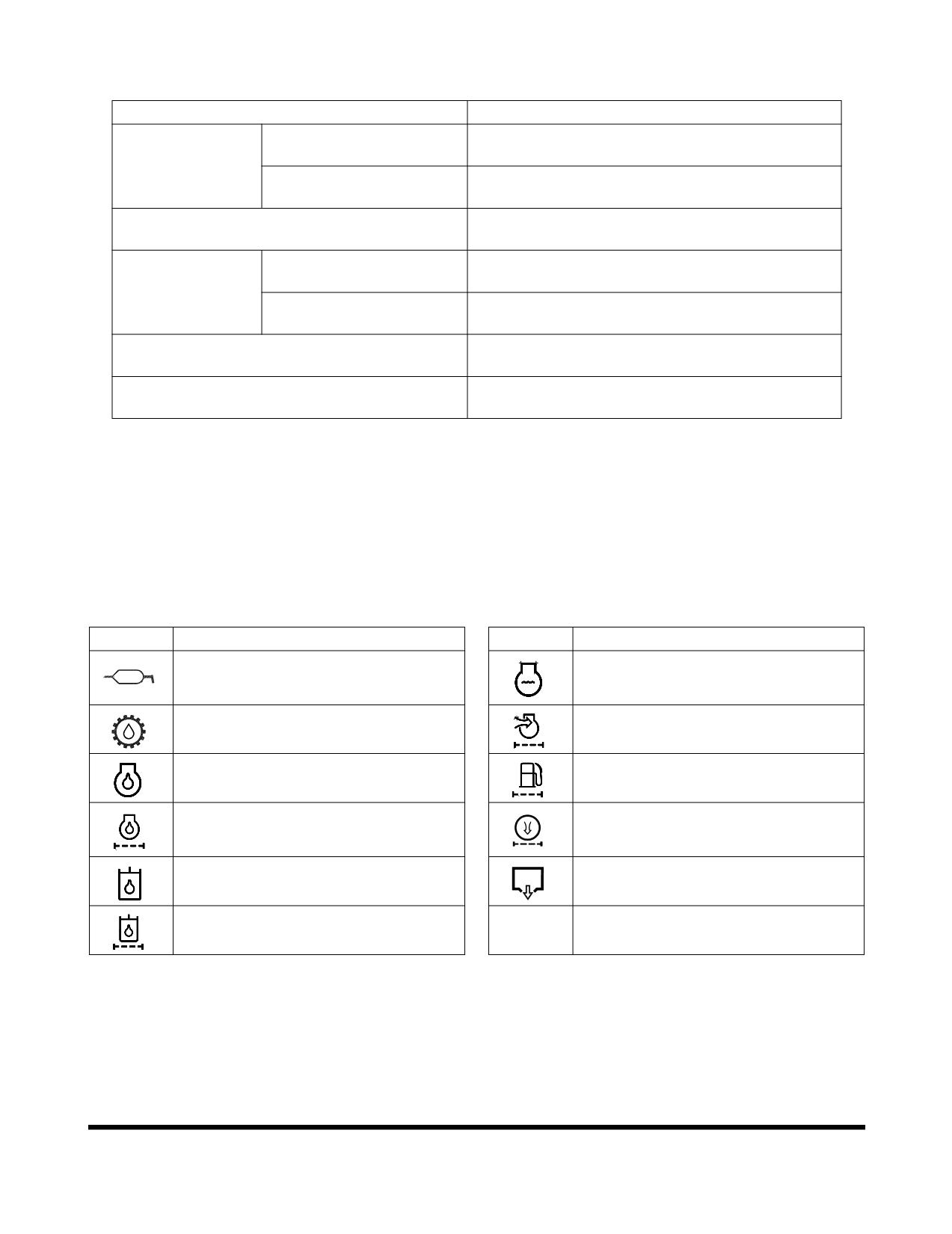
LUBRICATION AND SERVICE
CHART
Lubrication and service chart is on the inside of battery box
cover. The symbols shown here are used in the lubrication and
service chart on the next page.
Symbol
Description
Symbol
Description
Lubrication
Coolant
Gear Oil (Swing Device, Travel Device)
Air Cleaner Element
Engine Oil
Fuel Filter
Engine Oil Filter
Air Conditioner Filter
Hydraulic Oil
Drain Water
Hydraulic Oil Return Filter
Inspection, Maintenance and Adjustment
OP000599
4-8
OP000599
Inspection, Maintenance and Adjustment
4-9
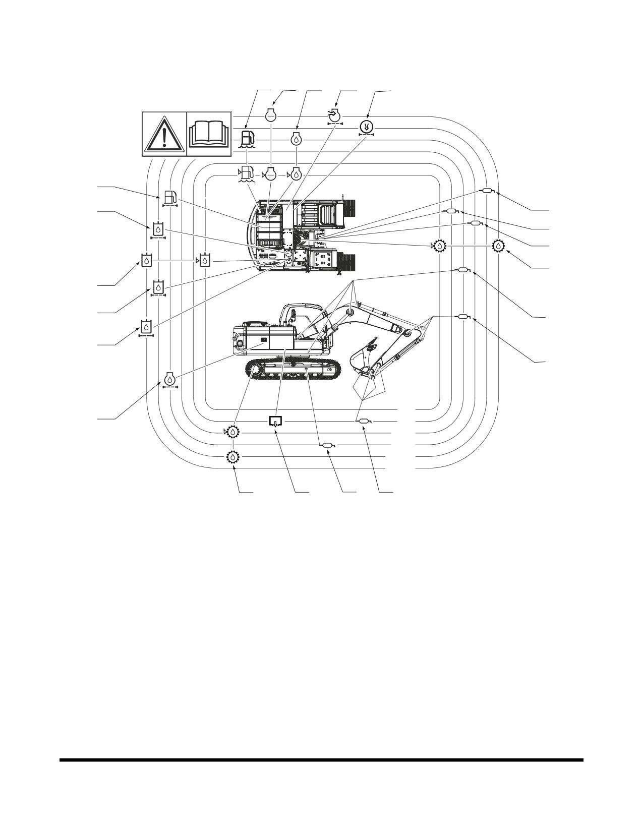
Description of Lubrication and Service Chart
12
13
9
19
20
18
14
5
3
4
6
10
15
1
16
1
10h
17
50h
250h
500h
1000h
2000h
8
11
7
1
FG009727
Figure 11
Inspection, Maintenance and Adjustment
OP000599
4-10
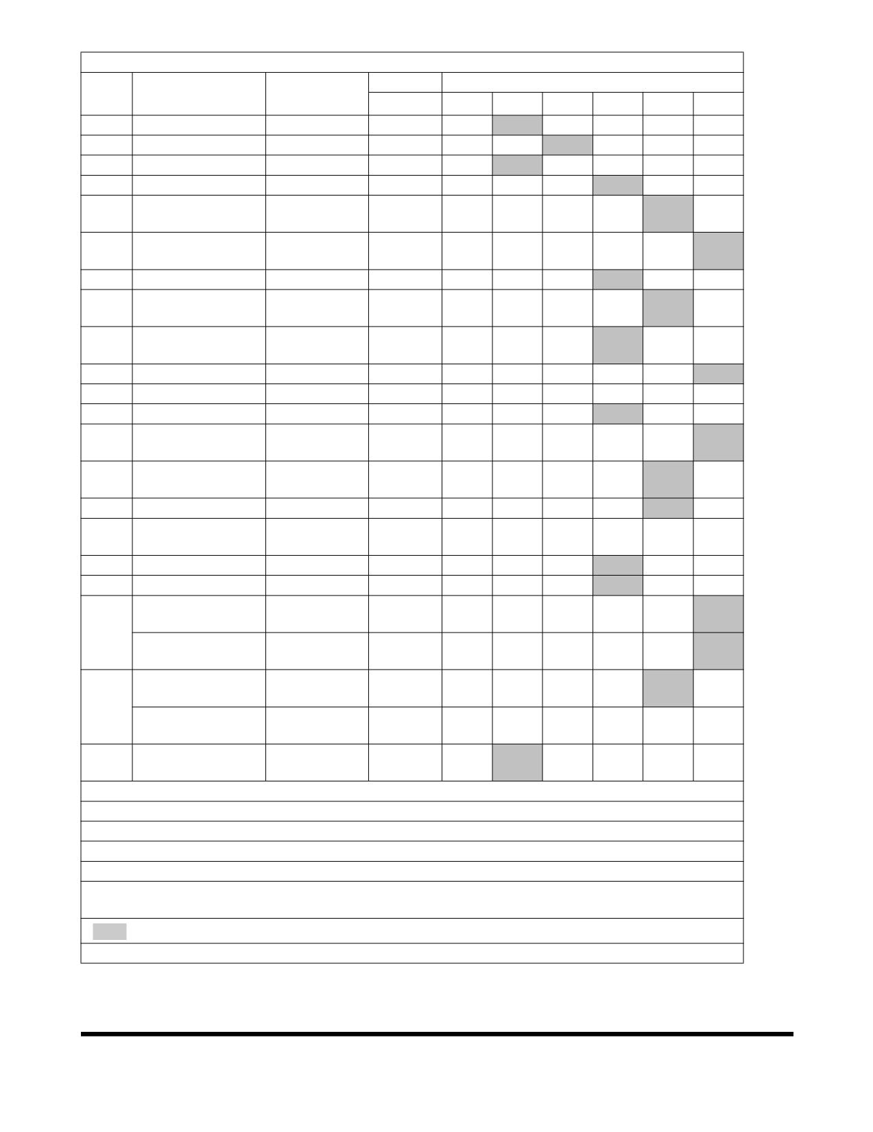
SERVICE DATA
Qty.
Service Interval
No.
Items to Check
Service
10
50
250
500
1000
2000
1
Front Joint Pin (1)
Grease
6
F100
W10
2
Front Joint Pin (2)
Grease
11
F100
W10
3
Swing Bearing
Grease
3
W10
4
Swing Gear
Grease
1
Swing Reduction
5
Grease
1
W10
Gear
Gear Oil
6
Swing Device
2 L
V
F
(80W90)
7
Track Spring
Grease
2
W10
Travel Reduction
Gear Oil
8
2X2.1 L
F, V
Device
(80W90)
Engine Oil
9
Engine Oil
22 L
V
F
(10W40)
10
Hydraulic Oil Tank
Hydraulic Oil
99 L
V
11
Fuel Tank
Diesel
267 L
V
12
Fuel Prefilter
Cartridge
1
V
Coolant
13
Radiator
20 L
V
PG
(Antifreeze)
Hydraulic Oil
14
Element
1
F
Return Filter
15
Pilot Filter
Element
1
F
Hydraulic Oil
16
Strainer
1
C
Suction Strainer
17
Engine Oil Filter
Cartridge
1
F
18
Fuel Filter
Cartridge
1
Air Cleaner
Element
1
C
(Outer)
19
Air Cleaner
Element
1
(Inner)
Air Conditioner
Cartridge
1
C
Filter (Outer)
20
Air Conditioner
Cartridge
1
C
Filter (Inner)
Dozer Blade Pin
21
Grease
6
F100
W10
(Optional)
V: Maintenance and Refill.
C: Cleaning.
F: First Time Exchange Only.
F100: Every 10 Hours For First 100 Hours.
W10: Every 10 Hours If Operating In Water.
PG: Propylene Glycol - Extended Life Antifreeze (Drain and replace using this interval.) See “Engine
Cooling System” on page 4-76, for further explanation.
: Replacement On Every Interval.
NOTE:
For additional service items see list of “Maintenance Intervals” on page 4-12.
OP000599
Inspection, Maintenance and Adjustment
4-11
MAINTENANCE INTERVALS
SERVICE ITEM
PAGE
10 Hour / Daily Service
Grease Boom, Arm and Front Attachment Pins (for first 100 hours)
4-14
Grease Dozer Blade Pin (Optional) (for first 100 hours)
4-14
Check Engine Oil Level
4-15
Check Level of Hydraulic Oil Tank
4-15
Check for Leaks in Hydraulic System
4-17
Check Fuel Level
4-18
Check for Leaks in Fuel System
4-18
Check Fuel Prefilter and Drain Water As Required
4-19
Check Oil Level of Swing Reduction Device
4-20
Clean Dust Net in Front of Oil Cooler and Intercooler
4-21
Check Cooling System and Refill As Required
4-21
Check Level of Window Washer Liquid
4-22
Inspect the Bucket Teeth and Side Cutters for Signs of Wear
4-22
Inspect Cooling Fan Blade
4-23
Check Air Intake System
4-23
Inspect Seat Belt for Proper Operation
4-23
Inspect the Structure for Cracks and Faulty Welds
4-24
Check the Operation of All Switches
4-24
Check the Operation of All Exterior Lights, Horn and Control Console Indicator and Monitor
4-24
Lights
Start Engine, Check Starting Ability, and Observe Exhaust Color at Start-up and at Normal
4-24
Operating Temperature. Listen for Any Abnormal Sounds
Check Operation of All Controls
4-25
50 Hour / Weekly Service
Perform All Daily Service Checks
4-26
Grease Arm and Front Attachment Pins
4-26
Grease Swing Bearing
4-27
Grease Dozer Blade Pin (Optional)
4-27
Drain Water and Sediment from Fuel Tank
4-28
Check Engine Fan Belt for Cracks, Wear and Correct Tension (After First 50 Hours)
4-28
Change Engine Oil and Filter (After First 50 Hours)
4-28
Inspect the Track Assemblies for Proper Tension and Loose, Worn or Damaged Parts
4-28
(Links, Shoes, Rollers, Idlers)
250 Hour / Monthly Service
Perform All Daily and 50 Hour Service Checks
4-29
Change Swing Reduction Device Oil (Drain and Refill After First 250 Hours)
4-29
Grease Arm and Front Attachment Pins
4-30
Check Engine Fan Belt Tension
4-32
Check Engine Fan Belt Wear
4-32
Check Oil Level in Travel Reduction Device (One on Each Side of Unit)
4-33
Change Breaker Filter Element (Optional)
4-34
Change Oil in Travel Reduction Device (One on Each Side of Unit) (After First 250 Hours)
4-34
Inspection, Maintenance and Adjustment
OP000599
4-12
SERVICE ITEM
PAGE
Replace Hydraulic Oil Return Filter (After First 250 Hours)
4-34
Change Pilot Filter (After First 250 Hours)
4-35
Inspect Pins and Bushings of the Front End Attachments for Signs of Wear
4-35
Check Fluid Levels in Batteries and Battery Charge Levels
4-35
Inspect for Any Loose or Missing Nuts and Bolts
4-35
Inspect Fuel System Hose Clamps
4-35
500 Hour / 3 Month Service
Perform All Daily, 50 and 250 Hour Service Checks
4-36
Grease Swing Gear and Pinion
4-36
Change Engine Oil and Filter
4-37
Clean Air-Conditioning Outer Filter
4-38
Check and Clean Air-Conditioning Inner Filter
4-39
Clean Radiator, Oil Cooler, Intercooler, Fuel Cooler and Air Conditioner Condenser Core
4-40
Clean Outer Filter of Air Cleaner
4-41
Change of Fuel Prefilter
4-42
Change Fuel Filter
4-43
1,000 Hour / 6 Month service
Perform All Daily, 50, 250 and 500 Hour Service Checks
4-45
Grease Swing Reduction Device
4-45
Replace Hydraulic Oil Return Filter
4-46
Change Pilot Filter
4-47
Change Oil in Travel Reduction Device (One on Each Side of Unit)
4-48
Change Air-Conditioning Outer Filter
4-49
Check Air Conditioner Refrigerant
4-50
Check and Adjust Engine **
4-51
2,000 Hour / Yearly Service
Perform All Daily, 50, 250, 500 and 1,000 Hour Service Checks
4-52
Change Swing Reduction Device Oil
4-52
Replace Outer and Inner Air Cleaner Elements
4-53
Change Radiator Coolant
4-54
Hydraulic Oil Exchange and Suction Strainer Cleaning
4-55
Check Alternator and Starter**
4-57
Check All Rubber Antivibration Shock Mounts
4-57
Perform and Record the Results of the Cycle Time Tests
4-57
Inspect Machine to Check for Cracked or Broken Welds or other Structural Damage
4-57
Check, Adjust Valve Clearance **
4-57
Check Head Bolt Torques
4-57
4,000 Hour / Biennial Service
Major Parts - Periodic Replacement
4-58
12,000 HOUR / SIX YEAR SERVICE
Hose In-service Lifetime Limit (European Standard ISO 8331 and EN982 CEN)
4-59
** These checks need to be completed by an authorized DOOSAN dealer.
OP000599
Inspection, Maintenance and Adjustment
4-13
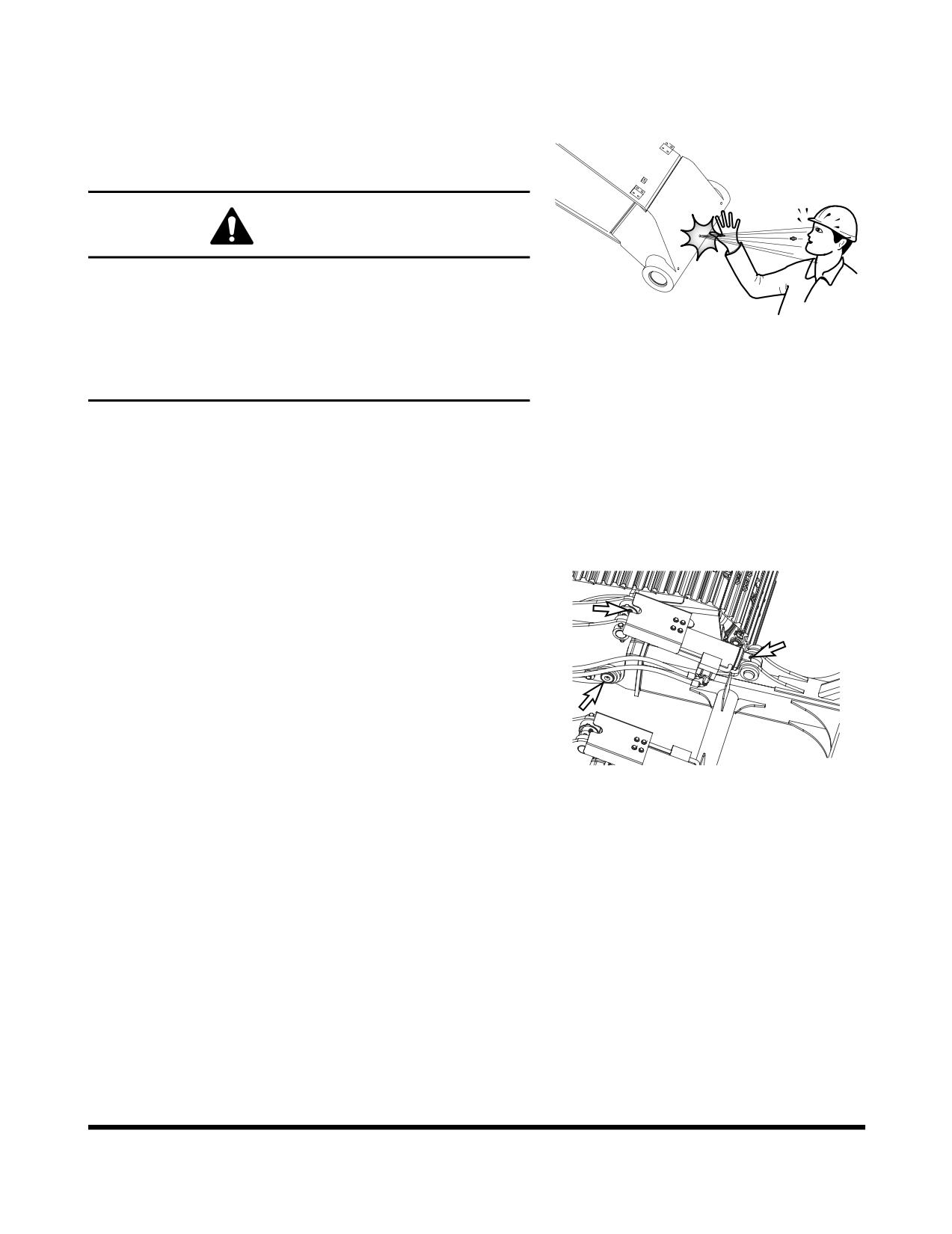
10 HOUR / DAILY SERVICE
Grease Boom, Arm and Front Attachment
Pins (for first 100 hours)
WARNING!
Do not remove the grease fitting until the pressure is
entirely bleed off by loosening grease fitting slowly to avoid
fatal wound.
FG000500
Let anybody never be in the blowing direction.
Figure 12
Be careful to any kinds of works for nipples and hydraulic
line plugs.
Grease every 10 hours for first 100 hours and every 50 or 250
hours thereafter (See page 4-26).
NOTE:
If the unit has been running or working in water the
front attachment should be greased on a 10 hour /
daily basis.
Grease Dozer Blade Pin (Optional) (for first
100 hours)
NOTE:
Grease it per 10 hours during initial period of 100
hours after buying your new machine, after which
period grease it per 50 hours.
NOTE:
In case of performing work underwater, grease it per
10 hours irrespective of elapsed period.
1.
Lower dozer blade to the ground.
FG009564
2.
Inject grease at total 6 points by 3 points per dozer cylinder
Figure 13
by means of using grease gun.
Neatly remove old grease that has leaked out after greasing.
Inspection, Maintenance and Adjustment
OP000599
4-14
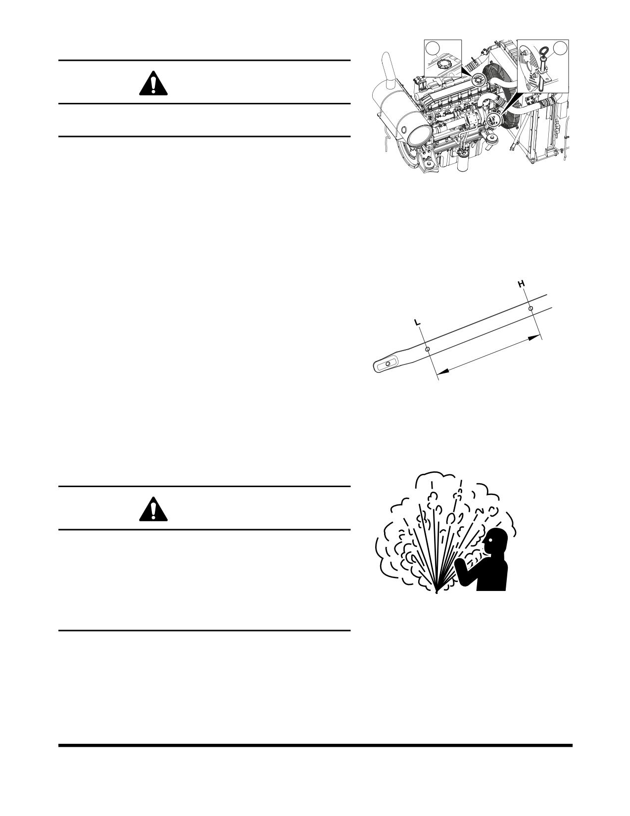
Check Engine Oil Level
2
1
WARNING!
Allow the engine to cool before checking the oil level to
avoid burns by touching hot engine parts.
NOTE:
When checking level using a dipstick always remove
and wipe it clean before making final level check.
FG000330
1.
Shut down engine and wait for fifteen minutes. This will
Figure 14
allow all oil to drain back to oil pan.
2.
Remove dipstick (1, Figure 14) and wipe the oil off with a
clean cloth.
3.
Insert dipstick fully in the oil gauge tube, then take it out
again.
4.
Engine oil level must be between "HIGH" and "LOW"
marks on dipstick.
NOTE:
If oil is above "HIGH" mark on dipstick, some
must be drained to return oil to proper level.
5.
Add oil through engine oil fill cap (2, Figure 14), if the oil
level is below the "LOW" mark.
FG000616
Figure 15
Check Level of Hydraulic Oil Tank
WARNING!
The hydraulic oil will be hot after normal machine
operation. Allow the system to cool before attempting to
service any of the hydraulic components.
The hydraulic tank is pressurized. Turn the breather cap
slowly to allow the pressurized air to vent. After the
ARO1760L
pressure has been released, it is safe to remove either the
Figure 16
fill cap or service covers.
OP000599
Inspection, Maintenance and Adjustment
4-15
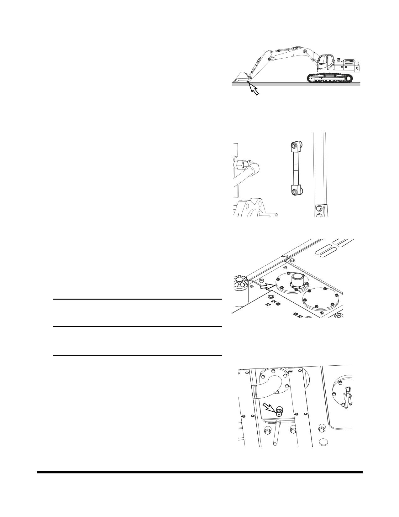
1.
Position the machine on firm, level ground. Lower boom
and position bucket on ground as shown in Figure 17.
2.
Set engine speed to "LOW IDLE."
FG000012
Figure 17
3.
Set safety lever to "LOCK" position.
4.
Check level gauge by opening right access door. Oil level
must be between marks on sight gauge.
H
L
FG000118
Figure 18
5.
If the level is below "L" mark add oil.
A.
Shut down engine.
B.
The hydraulic tank is pressurized. Turn the breather
cap slowly to allow the pressurized air to vent.
C.
Remove the upper cover of the hydraulic tank and
add oil.
IMPORTANT
FG009550
Figure 19
Do not fill above "H" mark on sight gauge. Overfilling
can result in damage to equipment and oil leaking
from hydraulic tank due to expansion.
6.
If oil level is above the "H" mark drain oil.
A.
Shut down engine and wait for the hydraulic oil to
cool down.
B.
Drain the excess oil from drain valve (Figure 20) at
the bottom of the tank into a suitable container, using
a hose connected to the valve.
NOTE:
Dispose of drained fluids according to local
regulations.
FG009551
Figure 20
Inspection, Maintenance and Adjustment
OP000599
4-16
Check for Leaks in Hydraulic System
1.
Perform a daily walk-around inspection to make sure that
the hoses, piping, fittings, cylinders and hydraulic motors
are not showing any signs of leakage. If any is noted,
determine the source of the leak and repair.
OP000599
Inspection, Maintenance and Adjustment
4-17
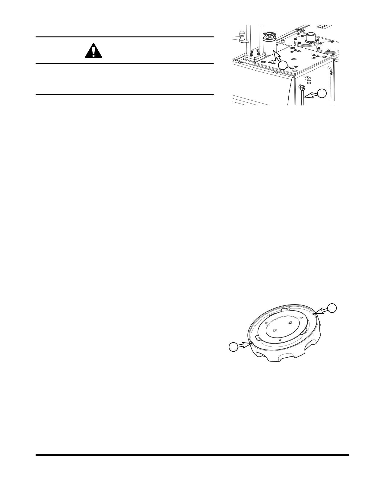
Check Fuel Level
WARNING!
1
Use extreme safety precautions while refueling to prevent
explosions or fire.
Immediately clean up any split fuel.
2
FG009552
1.
At end of each work day, fill fuel tank. Add fuel through fuel
fill tube (1, Figure 21). When working at a temperature of
Figure 21
0°C (32°F) or higher, use ASTM No. 2-D or its equivalent.
At temperatures below 0°C (32°F) use ASTM No. 1-D or its
equivalent.
2.
Make sure that the fuel fill hose is grounded to the
excavator before fueling begins.
3.
Check the amount of fuel in the tank by observing the fuel
tank sight gauge (2, Figure 21).
NOTE:
See “Fluid Capacities” on page 4-8. for
capacity.
4.
The excavator may be equipped with the optional battery
operated fuel fill pump. The pump assembly is in the
hydraulic pump compartment. Put the suction hose of the
pump into the fuel resupply tank. Turn the switch in the
pump compartment "ON," and the fuel will be pumped into
the excavator fuel tank.
NOTE:
See “Fuel Transfer Pump (Optional)” on
page 4-78, for further information.
5.
Do not overfill the tank.
6.
Securely tighten cap after fueling.
NOTE:
If breather holes (3, Figure 22) in cap are
clogged, a vacuum may form in the tank
preventing proper fuel flow to engine. Keep
3
holes in fuel cap clean.
3
FG000317
Figure 22
Check for Leaks in Fuel System
1.
Perform an inspection of the engine compartment to verify
that the fuel system is not leaking. If any is noted,
determine the source of the leak and repair.
Inspection, Maintenance and Adjustment
OP000599
4-18
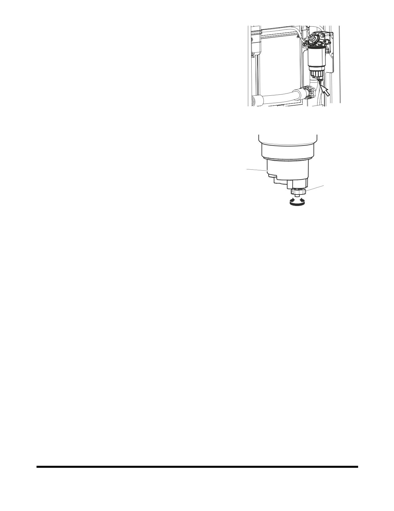
Check Fuel Prefilter and Drain Water As
Required
1.
A fuel prefilter is inside the left rear side access door.
2.
Open the access door on left rear side of the machine.
FG009554
Figure 23
3.
It is necessary to drain the collected water if the bowl is full
of water or sediment.
4.
Position a small container under fuel prefilter. Drain water
or sediment by opening drain valve (2, Figure 24) on
bottom of bowl (1).
1
NOTE:
Dispose of drained fluids according to local
regulations.
2
5.
Close drain valve.
open
close
FG000438
Figure 24
OP000599
Inspection, Maintenance and Adjustment
4-19
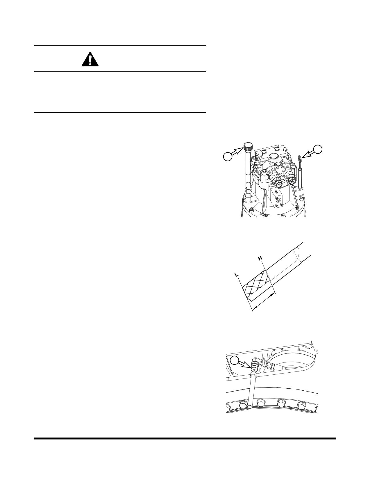
Check Oil Level of Swing Reduction
Device
WARNING!
The gear oil is very hot after the machine has been
operating. Shut all systems down and allow them to cool.
Before fully removing any motor case inspection port plug,
etc., loosen the plug slightly to allow pressurized air to
escape.
NOTE:
When checking level using a dipstick always remove
and wipe it clean before making final level check.
1.
Remove dipstick (1, Figure 25) and wipe the oil from the
dipstick with a cloth.
1
2
2.
Insert dipstick (1, Figure 25) fully into dipstick tube.
FG009555
Figure 25
3.
When dipstick is pulled out, oil level must be between
"HIGH" and "LOW" marks on dipstick.
NOTE:
If oil is above "HIGH" mark on dipstick, some
must be drained to proper level.
4.
If the oil does not reach the "L" mark on the dipstick, add oil
through fill port (2, Figure 25).
FG000419
Figure 26
5.
If the oil level exceeds the "H" mark on the dipstick, open
cap (3, Figure 27) of drain valve and connect hose (4) to
the valve. Drain the excessive oil into a suitable container.
3
NOTE:
Dispose of drained fluids according to local
regulations.
FG009556
Figure 27
Inspection, Maintenance and Adjustment
OP000599
4-20
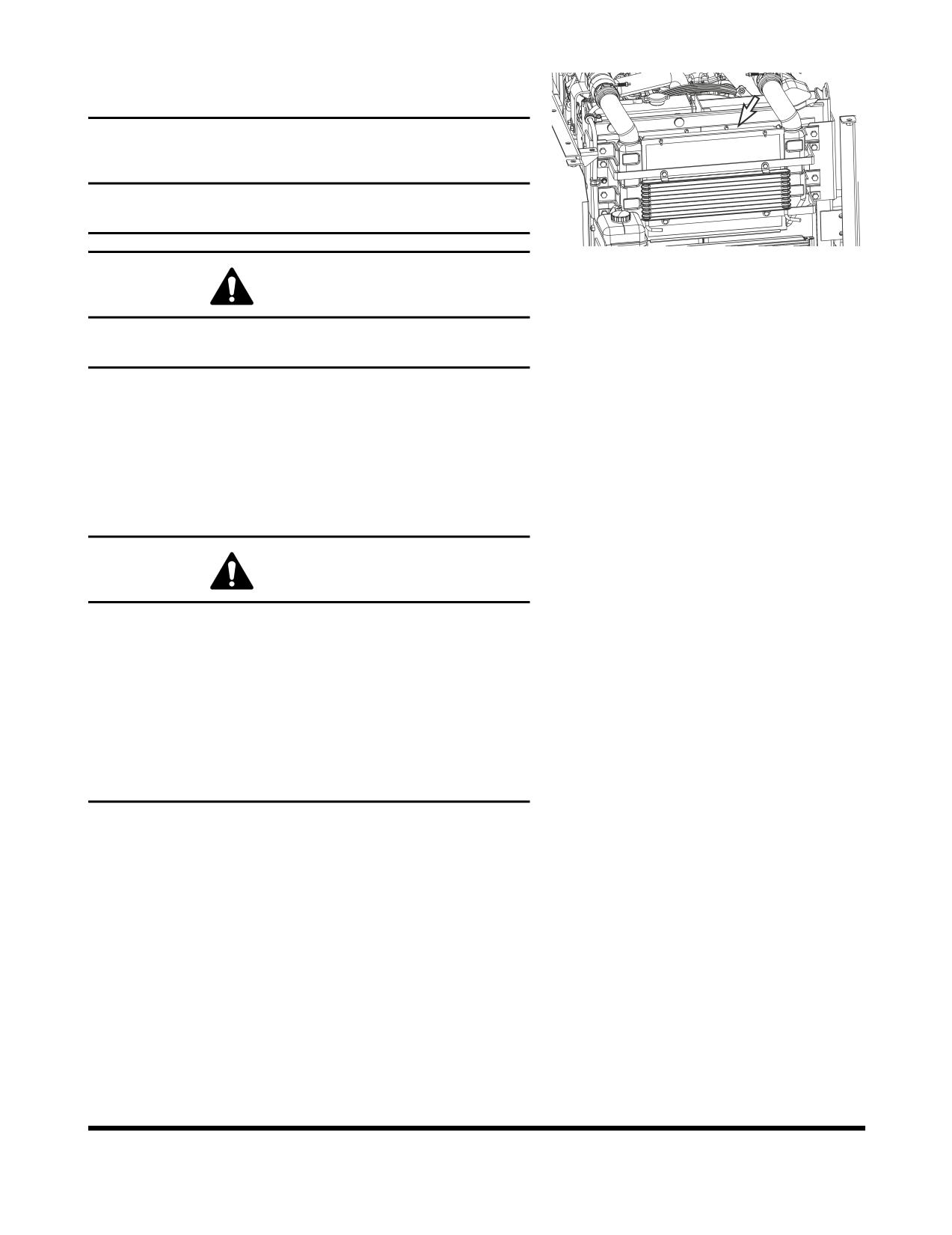
Clean Dust Net in Front of Oil Cooler and
Intercooler
IMPORTANT
If running excavator in dusty area, check
dust net
everyday and clean it if dirty.
FG006307
Figure 28
WARNING!
If using compressed air or water to clean the dust net, make
sure that proper eye protection is worn.
1.
Loosen the wing bolt(s) and remove dust net.
2.
Clean with compressed air or water.
Check Cooling System and Refill As
Required
WARNING!
Allow the engine to cool before releasing the radiator cap.
Make sure to loosen the cap slowly to release any
remaining pressure.
Radiator cleaning is performed while the engine is running.
Take extreme caution when working on or near a running
engine. Make sure to lock out and tag the controls notifying
personnel that service work is being performed.
Do not remove the radiator cap unless it is required.
Observe the coolant level in the coolant recovery tank.
NOTE:
Do not mix ethylene glycol and propylene glycol
antifreeze together. If the two are mixed, the
protection level will be reduced to the level of the
ethylene glycol.
OP000599
Inspection, Maintenance and Adjustment
4-21
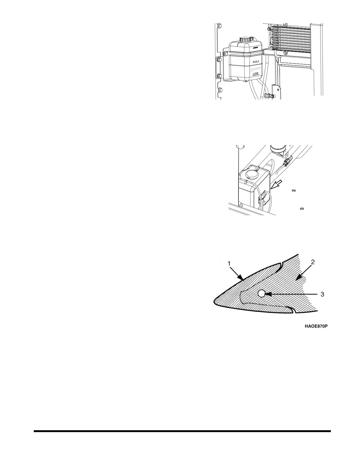
1.
When the engine is cold, remove the radiator cap and
check the coolant level inside the radiator. Do not rely on
the level of coolant in the coolant recovery tank. Refill
radiator as required. Refer to coolant concentration table.
(See page 4-77)
2.
Check to make sure that the coolant transfer line from the
coolant recovery tank to the radiator is free and clear of
obstructions, or not pinched.
3.
Observe the level of coolant in the coolant recovery tank.
The normal cold engine fluid level should be between
FG009558
"FULL" and "LOW" marks on tank.
Figure 29
4.
If the coolant is below the "LOW" mark, add coolant to this
tank.
Check Level of Window Washer Liquid
1.
Open left front access door and check fluid level in
windshield washer tank.
2.
Open fill cap and add fluid.
NOTE:
Use a washer liquid that is rated for all seasons.
This will prevent freezing during cold weather
operation.
FG009559
Figure 30
Inspect the Bucket Teeth and Side Cutters
for Signs of Wear
1.
On a daily basis, inspect the bucket teeth to make sure that
tooth wear or breakage has not developed.
2.
Do not allow the replaceable bucket teeth to wear down to
the point that the bucket adapter is exposed. See Figure
31.
NOTE:
These instructions are only for DOOSAN OEM
buckets. If you are using other manufacturers'
buckets, refer to their specific instructions.
Figure 31 1. POINT, 2. ADAPTER and 3.
PIN
Inspection, Maintenance and Adjustment
OP000599
4-22
Inspect Cooling Fan Blade
WARNING!
Personal injury can result from a fan blade failure. Never
pull or pry on the fan. This can damage the fan blade(s) and
cause fan failure.
1.
An inspection of the cooling fan is required daily. Check for
cracks, loose bolts, bent or loose blades, and for contact
Figure 32
between the blade tips and the fan shroud. Check the fan
to make sure it is securely mounted. Tighten the bolts if
necessary. Replace any fan that is damage.
Check Air Intake System
CAUTION!
Hot engine components can cause burns.
Avoid contact with hot engine components
1.
Park the machine on a level surface, lower the attachment
to the ground, set safety lever to "LOCK" position, and shut
HAOA050L
down engine.
Figure 33
2.
Check the engine intake hose, and hose bands for damage
and tightness.
3.
If damaged, wrinkled, or loose, replace or retighten or
contact your nearest DOOSAN dealer.
IMPORTANT
Severe engine damage will result from running with
unfiltered air.
Do not operate engine if any leaks or defects are found
FG006309
on air intake system.
Figure 34
Inspect Seat Belt for Proper Operation
OP000599
Inspection, Maintenance and Adjustment
4-23
Inspect the Structure for Cracks and
Faulty Welds
1.
During the daily walk-around inspection and when
greasing the machine, look for any visible damage to the
machine. Repair or replace any damaged parts before
operating the machine.
Check the Operation of All Switches
1.
Verify the working condition of all switches before starting
the engine.
Check the Operation of All Exterior Lights,
Horn and Control Console Indicator
and Monitor Lights
1.
Turn engine starter switch to the "I" (ON) position and
observe all of the indicator lights.
2.
Restore operation of any light bulbs that do not turn "ON"
at this time.
3.
Sound the horn. Repair or replace if required.
4.
Turn "ON" and inspect all exterior work lights. Replace any
monitors, burned out bulbs or cracked or broken housings
or lenses.
Start Engine, Check Starting Ability, and
Observe Exhaust Color at Start-up and
at Normal Operating Temperature.
Listen for Any Abnormal Sounds
Inspection, Maintenance and Adjustment
OP000599
4-24
Check Operation of All Controls
IMPORTANT
Cold weather operation requires that the operator fully
warm up the hydraulic oil before beginning machine
operation. Follow all warm up instructions listed in the
Operating Instruction section of this manual. Make sure to
cycle oil through all of the components, including all
cylinders, both travel motors and the swing motor. Cold
hydraulic oil in the lines and components needs to be
warmed before beginning full operation. If this is not done,
damage to the cylinders or hydraulic motors can occur.
1.
With the engine at rated speed, operate all of the controls.
2.
Follow cold weather hydraulic system warm-up
procedures.
3.
Note any slow operations or unusual movements.
Determine the cause and repair the fault before operating.
OP000599
Inspection, Maintenance and Adjustment
4-25
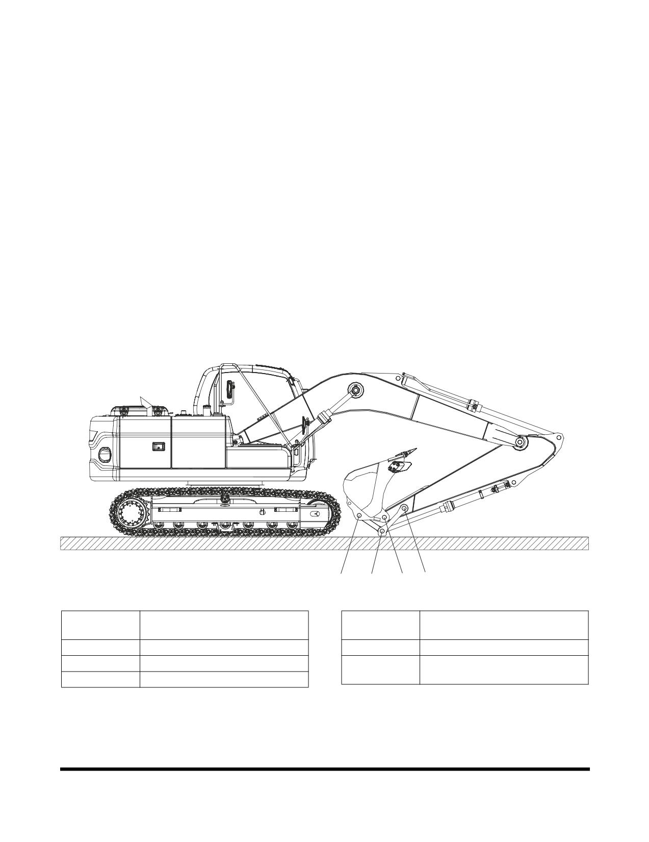
50 HOUR / WEEKLY SERVICE
Perform All Daily Service Checks
Grease Arm and Front Attachment Pins
Grease every 10 hours for first 100 hours and every 50 hours
thereafter.
NOTE:
If the unit has been running or working in water the
front attachment should be greased on a 10 hour /
daily basis.
•
Position machine as shown below and lower the front
attachment to the ground and shut down engine
•
Press the grease fitting and inject grease with the
grease gun on the marked point
•
After injection, clean off the old grease that has been
purged.
D
B,E
C
A
FG009560
Figure 35
Reference
Reference
Description
Description
Number
Number
A
Arm Link Joint Pin (1 Points)
D
Bucket Link Joint Pin (1 Point)
B
Link Joint Pin (2 Points)
E
Bucket Cylinder Rod Pin
(1 Point)
C
Arm Bucket Joint Pin (1 Points)
Inspection, Maintenance and Adjustment
OP000599
4-26
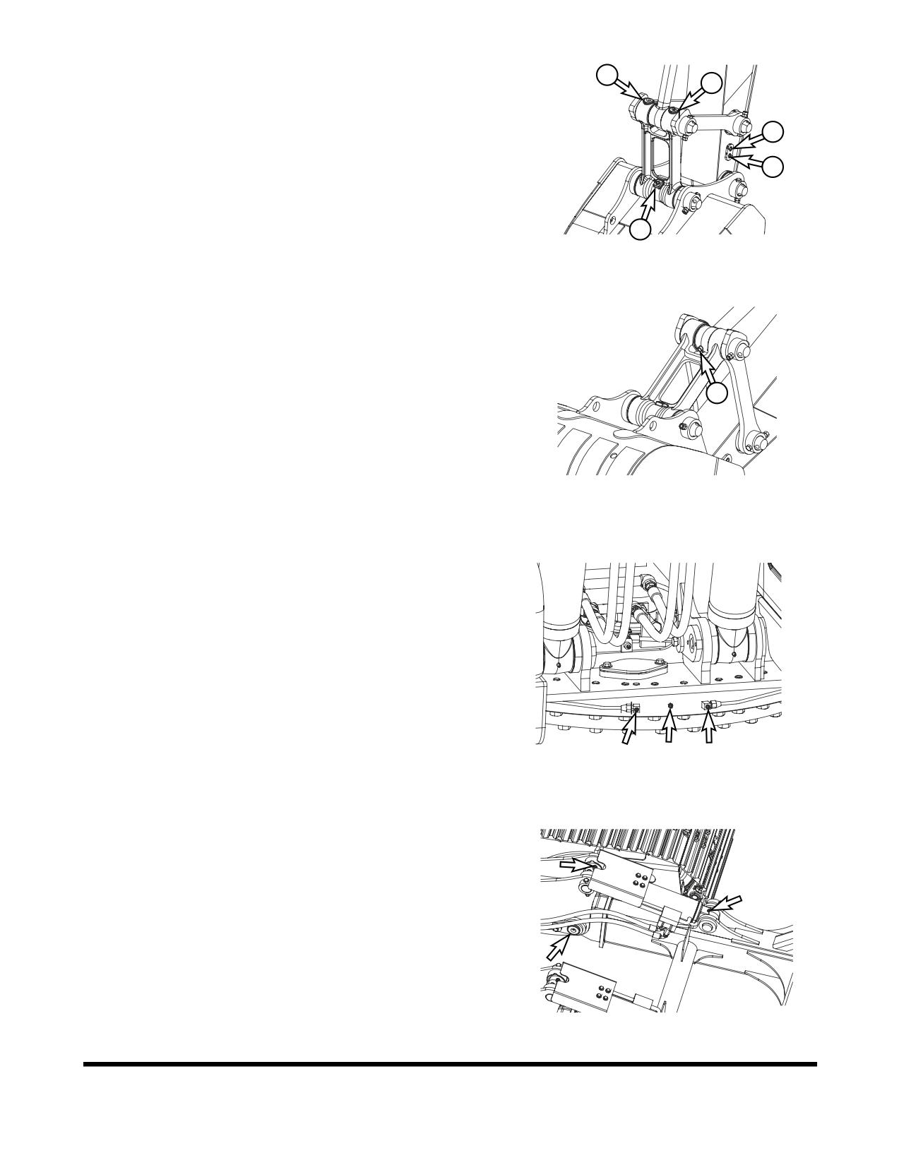
A.
Arm link joint pin (1 point)
B
B.
Link joint pin (2 points)
B
C.
Arm bucket joint pin (1 point)
A
D.
Bucket link joint pin (1 point)
C
D
FG009561
Figure 36
E.
Bucket cylinder rod pin (1 point)
E
FG009562
Figure 37
Grease Swing Bearing
1.
Position the machine on firm, level ground. Lower the front
attachment to the ground and shut down engine.
2.
There are three grease fittings for the swing bearing. Do
not over lubricate. Purge old grease with new. Remove all
purged grease.
FG009563
Figure 38
Grease Dozer Blade Pin (Optional)
NOTE:
Grease it per 10 hours during initial period of 100
hours after buying your new machine, after which
period grease it per 50 hours.
NOTE:
In case of performing work underwater, grease it per
10 hours irrespective of elapsed period.
1.
Lower dozer blade to the ground.
2.
Inject grease at total 6 points by 3 points per dozer cylinder
by means of using grease gun.
FG009564
Figure 39
3.
Neatly remove old grease that has leaked out after greasing.
OP000599
Inspection, Maintenance and Adjustment
4-27
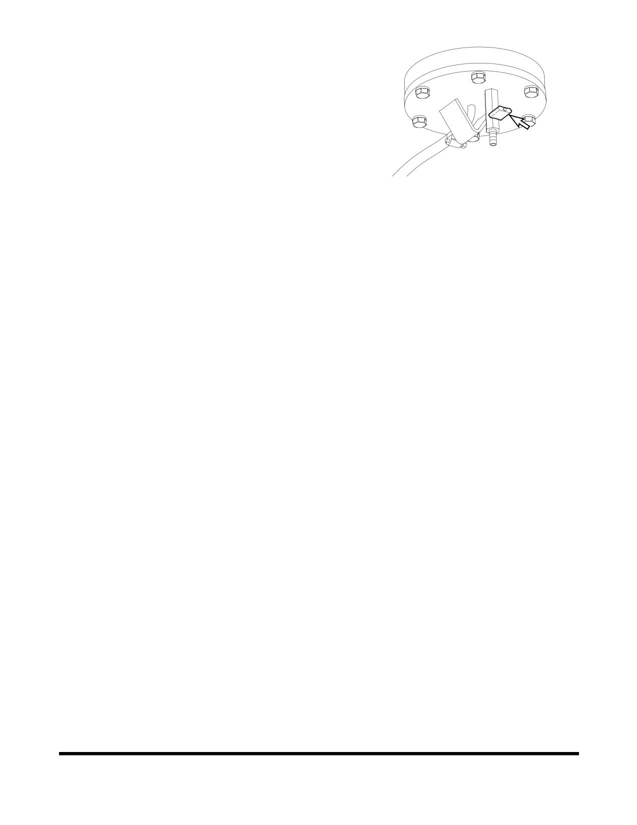
Drain Water and Sediment from Fuel Tank
1.
Perform this procedure before operating the machine.
2.
Drain water and sediment from bottom of fuel tank into a
suitable container.
NOTE:
Dispose of drained fluid according to local
regulations.
NOTE:
Always completely fill fuel tank at end of each
workday to prevent condensation from forming
on the inside walls of the tank.
FG000296
Figure 40
Check Engine Fan Belt for Cracks, Wear
and Correct Tension (After First 50
Hours)
1.
Inspect after first 50 hours of operation and every 250
hours thereafter. For details, See “Check Engine Fan Belt
Tension” on page 4-32.
Change Engine Oil and Filter (After First 50
Hours)
1.
Change engine oil and filter after first 50 hours of operation
or rebuild, then every 500 thereafter. For details, See
“Change Engine Oil and Filter” on page 4-37.
Inspect the Track Assemblies for Proper
Tension and Loose, Worn or Damaged
Parts (Links, Shoes, Rollers, Idlers)
1.
Do a daily walk-around inspection of all components
including the track assemblies. Look for missing, damaged
or excessively worn parts. See “Track Tension” on
page 4-82.
2.
Jack up each track and perform the two speed travel motor
test.
Inspection, Maintenance and Adjustment
OP000599
4-28
250 HOUR / MONTHLY SERVICE
Perform All Daily and 50 Hour Service
Checks
Change Swing Reduction Device Oil (Drain
and Refill After First 250 Hours)
NOTE:
Change swing reduction device oil after first
250
hours on a new machine and every 2,000 hours
thereafter (See page 4-52).
OP000599
Inspection, Maintenance and Adjustment
4-29
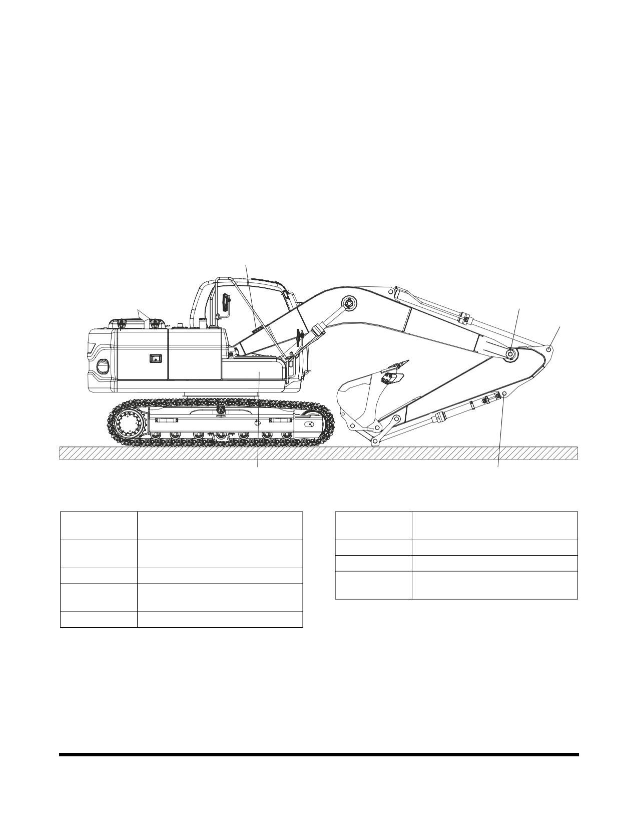
Grease Arm and Front Attachment Pins
Grease every 10 hours for first 100 hours and every 250 hours
thereafter.
NOTE:
If the unit has been running or working in water the
front attachment should be greased on a 10 hour /
daily basis.
•
Position machine as shown below and lower the front
attachment to the ground and shut down engine
•
Press the grease fitting and inject grease with the
grease gun on the marked point
•
After injection, clean off the old grease that has been
purged.
B,C,D
E
F
A
G
FG009723
Figure 41
Reference
Reference
Description
Description
Number
Number
A
Boom Cylinder Head Pin (2
E
Boom Arm Joint Pin (2 Points)
Points)
F
Arm Cylinder Rod Pin (1 Point)
B
Boom Foot Pin (2 Points)
G
Bucket Cylinder Head Pin
C
Boom Cylinder Rod Pin
(1 Point)
(2 Points)
D
Arm Cylinder Head Pin (1 Point)
Inspection, Maintenance and Adjustment
OP000599
4-30
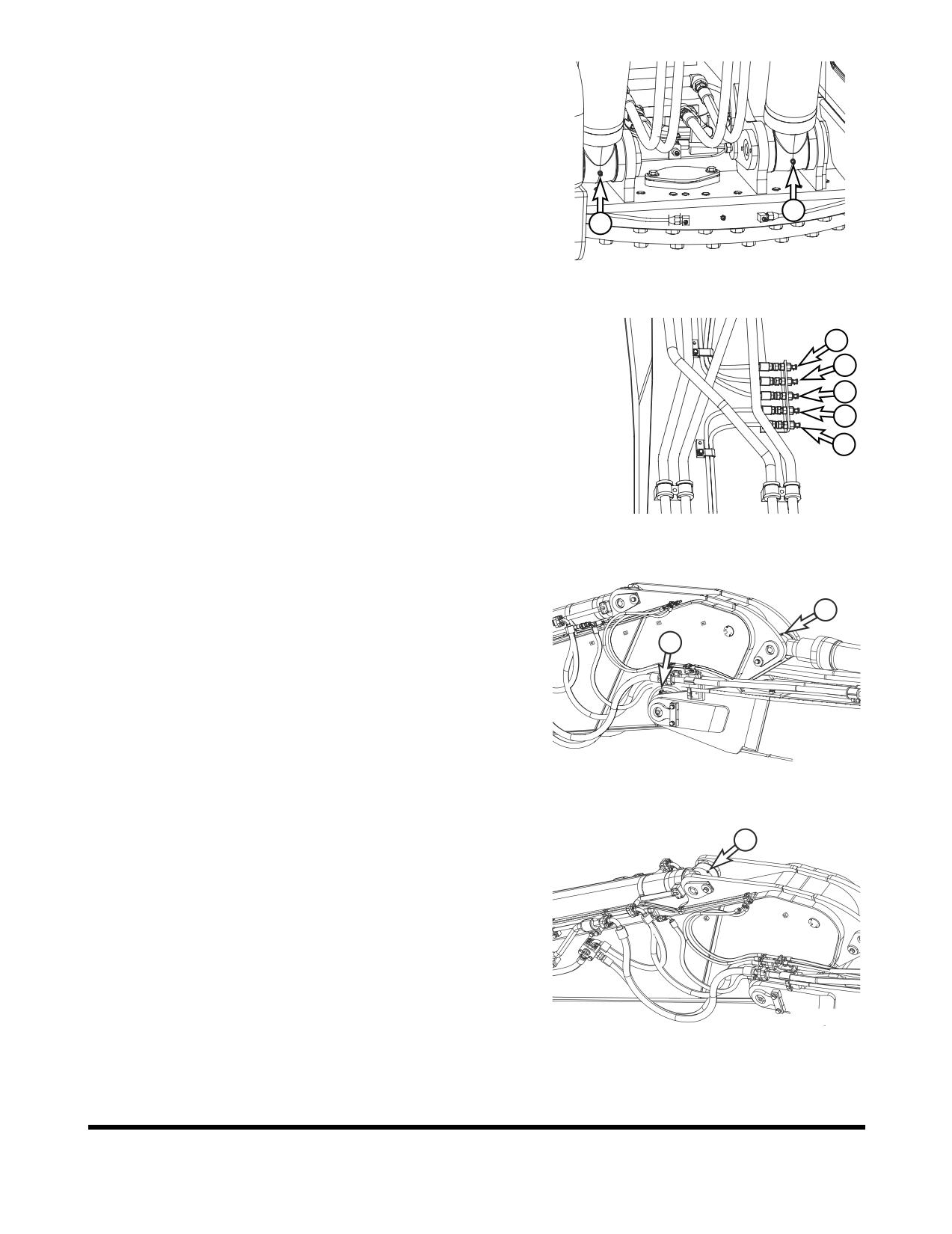
A.
Boom cylinder head pin (2 points)
A
A
FG009566
Figure 42
B.
Boom foot pin (2 points)
C.
Boom cylinder rod pin (2 points)
C
D
D.
Arm cylinder head pin (1 point)
C
B
B
FG009567
Figure 43
E.
Boom arm joint pin (2 points)
F.
Arm cylinder rod pin (1 point)
F
E
FG006458
Figure 44
G. Bucket cylinder head pin (1 point)
G
FG006459
Figure 45
OP000599
Inspection, Maintenance and Adjustment
4-31
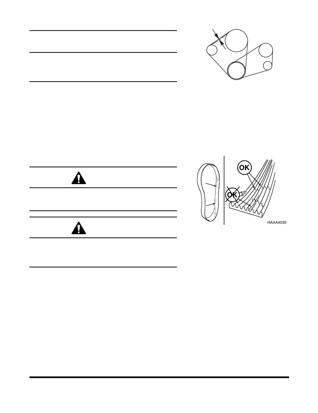
Check Engine Fan Belt Tension
FAN
10mm/10kg
COMPRESSOR
IMPORTANT
A loose fan belt can cause engine overheating, poor
ALTERNATOR
charging, and/or premature belt wear. A belt that is too tight
can cause damage to the water pump, alternator bearing or
belt.
CRANKSHAFT
FG000353
1.
Inspect every 250 hours. (Inspect after first 50 hours of
Figure 46
operation.)
2.
With the engine shut off, check the tension of the fan belt
by pressing downwards on the belt, midway between the
fan pulley and alternator pulley. The belt should flex
approximately 10 mm (0.4 in). See Figure 46. To adjust the
belt, loosen the alternator adjustment plate bolts, adjust the
belt tension and retighten the bolts.
Check Engine Fan Belt Wear
WARNING!
Keep clear of engine fan and fan drive belts when the
engine is running. Rotating fan and belt contact can cause
injury.
Figure 47
WARNING!
When checking, adjusting or replacing drive belts, care
must be taken to prevent accidental cranking of the engine.
Be sure the starter switch is in the "OFF" position and the
controls are tagged.
1.
Replace badly worn, greasy or severely cracked belts
immediately. These conditions prevent proper belt
function. Visually inspect the belt. Check the belt for
intersecting cracks. Transverse (across the belt width)
cracks are acceptable. Longitudinal (direction of belt
length) cracks that intersect with transverse cracks are not
acceptable. Replace the belt if it is frayed or has pieces of
material missing.
2.
Before installing new belts, make sure all pulley grooves
are clean and not worn. Replace pulley, if damaged, or if
the grooves are worn.
3.
All pulley support bearings, shafts, and brackets must be in
working order.
Inspection, Maintenance and Adjustment
OP000599
4-32
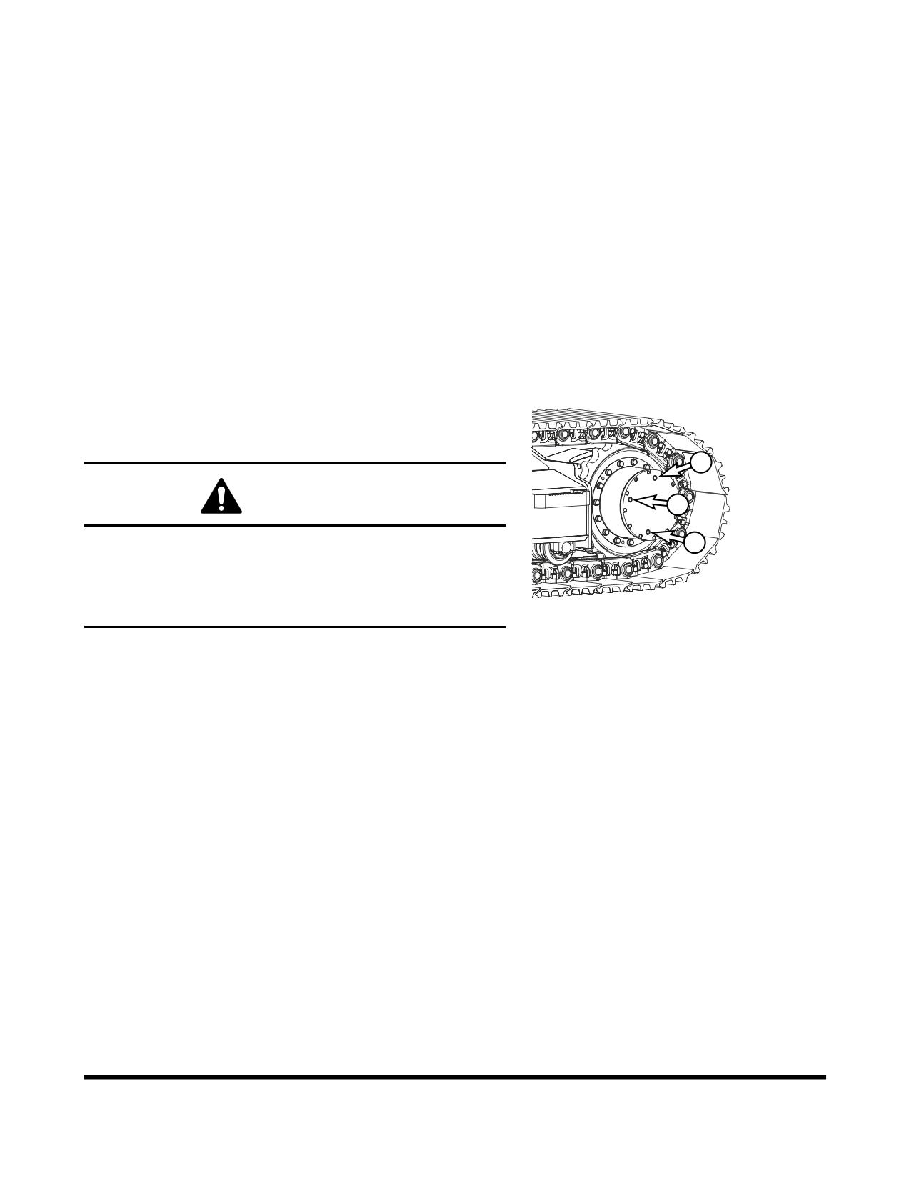
4.
When replacing belts and pulleys, pulley alignment must
be checked with belts tensioned and brackets securely
clamped. A misalignment that can be detected by the
naked eye is detrimental to belt performance.
5.
Do not force the belts into the pulley grooves by prying with
a screwdriver or pry bar. This will damage the belt side
cords which will cause the belts to turn and result in
complete destruction of the belts in operation.
6.
Belts on new machines and replacement belts lose their
tension as they seat into the pulley grooves. Check the
tension of new belts at 50 hour intervals until tension is
stabilized and thereafter, every 250 hours. If the tension
falls below the required minimum, the belt slips damaging
the belts and pulley grooves.
NOTE:
When operating in abrasive conditions, check
tension every 100 hours.
Check Oil Level in Travel Reduction
Device (One on Each Side of Unit)
3
WARNING!
1
2
The gear oil is very hot after the machine has been
operating. Shut all systems down and allow them to cool.
Before fully removing any motor case inspection port plug,
FG009568
etc., loosen the plug slightly to allow pressurized air to
escape.
Figure 48
1.
Make sure that the machine is on firm, level ground.
2.
Rotate the track until ports (1 thru 3, Figure 48) are in their
proper positions as shown.
3.
Loosen fill plug (3, Figure 48) slightly to allow pressurized
air to escape.
4.
Remove oil level plug (1, Figure 48).
5.
Check oil level. The oil should be near the bottom of the
level plug opening.
6.
Add oil through the fill plug (3, Figure 48) opening, if
necessary.
7.
Clean and install oil level and fill plugs (1 and 3, Figure 48).
8.
Repeat this procedure on the other travel reduction device.
OP000599
Inspection, Maintenance and Adjustment
4-33
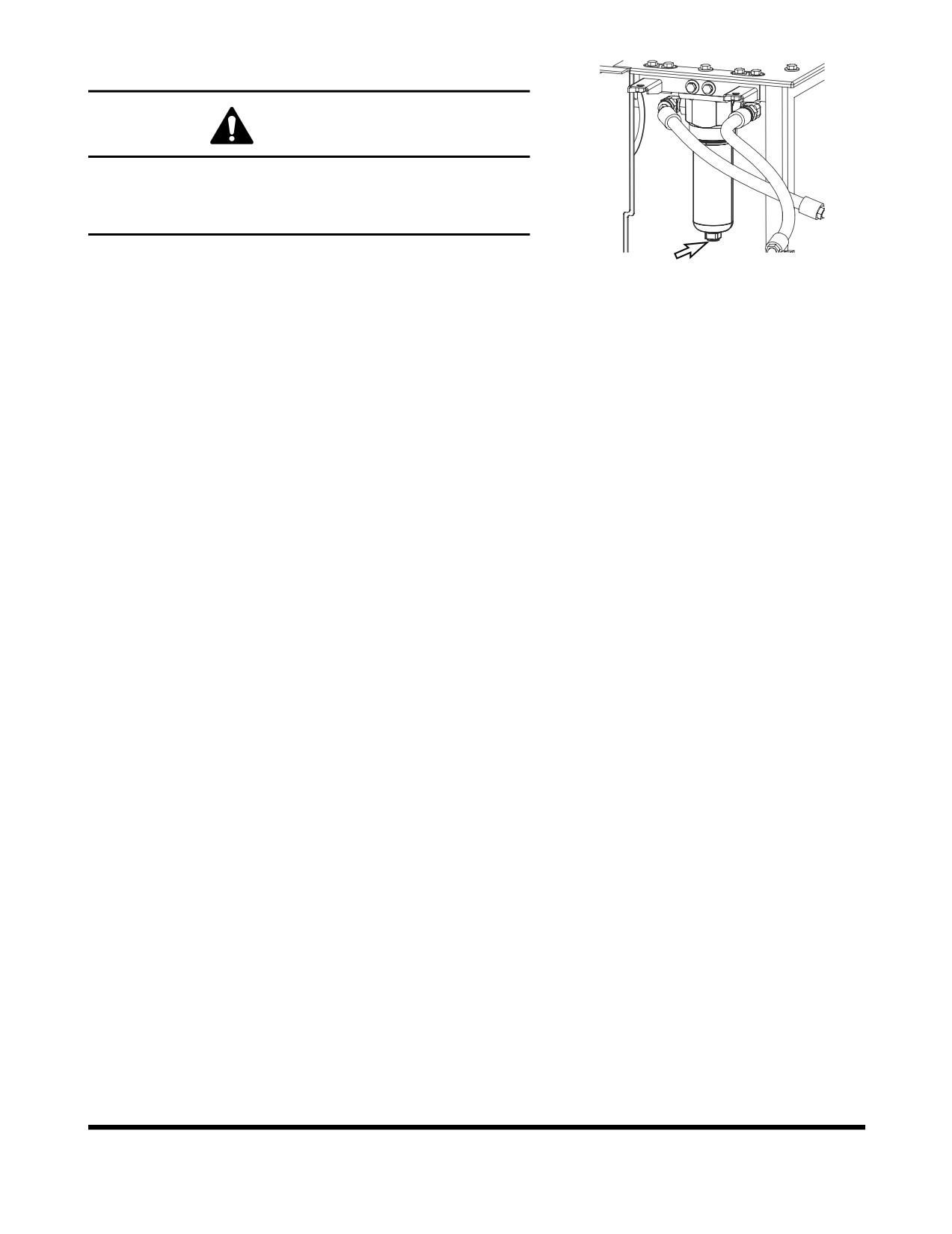
Change Breaker Filter Element (Optional)
WARNING!
The hydraulic oil will be hot after normal machine
operation.
Allow the system to cool down before changing pilot filter.
FG009569
1.
Position the machine on firm, level ground. Lower the front
attachment to the ground and shut down engine.
Figure 49
2.
Loosen the hydraulic oil tank breather cap to release
pressure.
3.
Locate breaker filter assembly (Figure 49).
4.
Position a container under the filter assembly. Remove the
drain plug and completely drain the assembly.
5.
Using a 30 mm spanner, unscrew filter housing from filter
bottom.
6.
Remove O-ring from filter head.
7.
Replace filter.
8.
Apply a small amount of oil around the entire O-ring and
install the filter housing on the filter head.
NOTE:
Tightening torque : 27 kg•m (265 Nm, 195 ft lb)
9.
Install drain plug in bottom of filter housing.
10. After changing breaker filter, vent air from pump and check
level of hydraulic oil tank.
Change Oil in Travel Reduction Device
(One on Each Side of Unit) (After First
250 Hours)
NOTE:
Drain and refill oil after first 250 hours of operation or
rebuild, and every 1,000 hours thereafter (See page
4-48).
Replace Hydraulic Oil Return Filter (After
First 250 Hours)
NOTE:
Replace hydraulic oil return filter after first 250 hours
of operation or rebuild, then every
1,000 hours
thereafter (See page 4-46).
Inspection, Maintenance and Adjustment
OP000599
4-34
Change Pilot Filter (After First 250 Hours)
NOTE:
Change pilot filter after first 250 hours and every
1,000 hours thereafter (See page 4-47).
Inspect Pins and Bushings of the Front
End Attachments for Signs of Wear
Check Fluid Levels in Batteries and
Battery Charge Levels
Inspect for Any Loose or Missing Nuts and
Bolts
Inspect Fuel System Hose Clamps
OP000599
Inspection, Maintenance and Adjustment
4-35
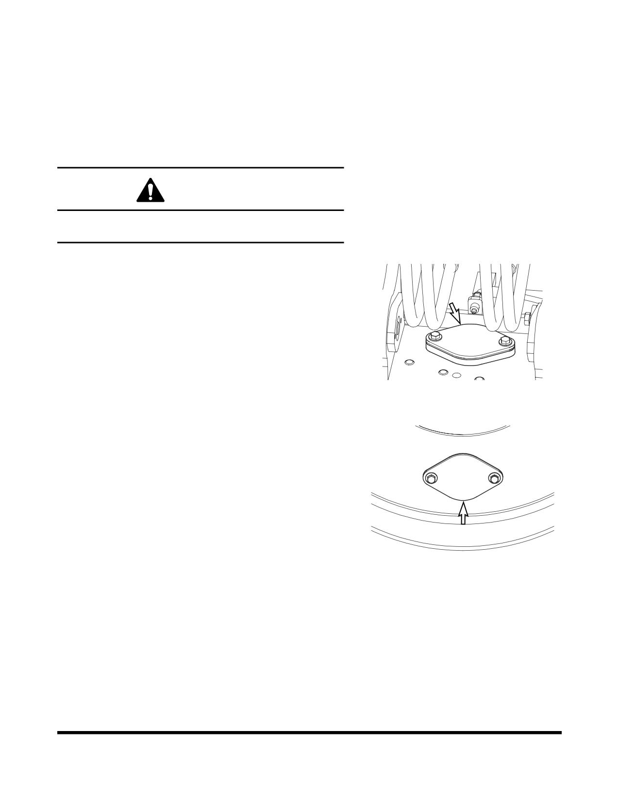
500 HOUR / 3 MONTH SERVICE
Perform All Daily, 50 and 250 Hour Service
Checks
Grease Swing Gear and Pinion
WARNING!
Greasing swing gear and pinion must be serviced by only
one person.
1.
Remove inspection cover and inspect the condition of the
grease. Make sure that water or other contaminants are
not noticeable.
NOTE:
The upper structure must be rotated a little at a
time so that the entire face of the swing gear
can be lubricated. Use extreme caution when
performing this operation.
FG009570
Figure 50
2.
If water or other contaminations are found, remove the
lower access cover so that the gear teeth can be
thoroughly cleaned and lubricated.
3.
Install access covers after lubricating gear teeth.
FG009571
Figure 51
Inspection, Maintenance and Adjustment
OP000599
4-36
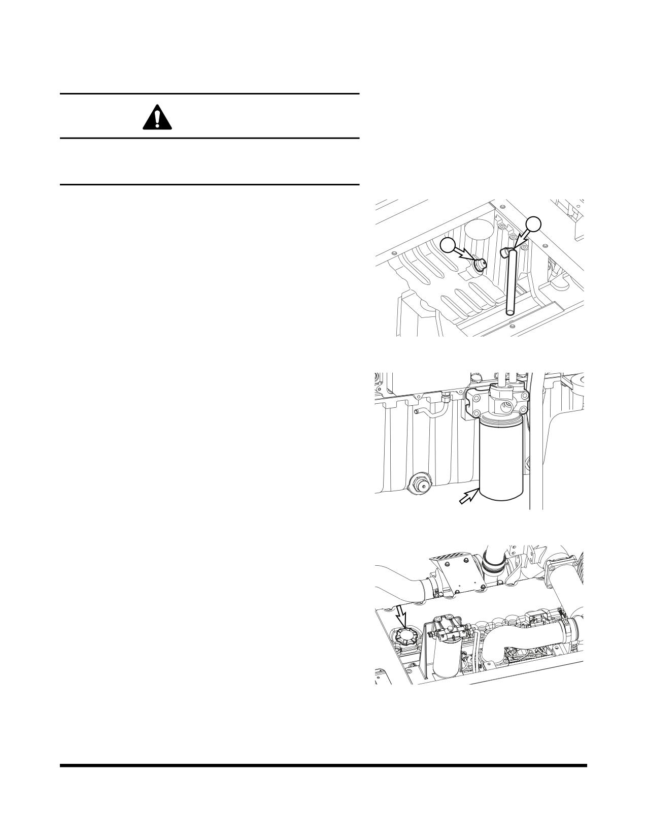
Change Engine Oil and Filter
NOTE:
Change engine oil and filter after first 50 hours of
operation or rebuild, then every 500 thereafter.
WARNING!
DO NOT change oil on a hot engine. Allow the engine to
cool down before attempting to change the engine oil and
filter to avoid burns by touching hot engine parts.
1.
Position a larger container under the engine. Remove cap
(1, Figure 52) and install hose (2) to drain the engine oil.
Remove hose (2) and install cap (1).
2
NOTE:
Dispose of drained fluids according to local
1
regulations.
FG003398
Figure 52
2.
Replace engine oil filter by using filter wrench. The engine
oil filter is a spin-on type. See Figure 53. Remove and
discard filter.
3.
Install new filter. Apply a small amount of oil around filter
gasket. Screw filter on head until gasket contacts head,
turn filter 1/2 turn more.
FG007057
Figure 53
4.
Refill the engine with the correct oil through the oil fill port
(Figure 54). Refer to the Lubrication Table of this manual
for the recommended oil for the operating conditions.
NOTE:
See “Fluid Capacities” on page 4-8. for
capacity.
5.
Start engine. Run engine for five minutes at "LOW IDLE,"
and check engine oil pressure light.
6.
Shut down engine. Look for signs of leaks at filter. Recheck
oil level after fifteen minutes.
FG006410
Figure 54
OP000599
Inspection, Maintenance and Adjustment
4-37
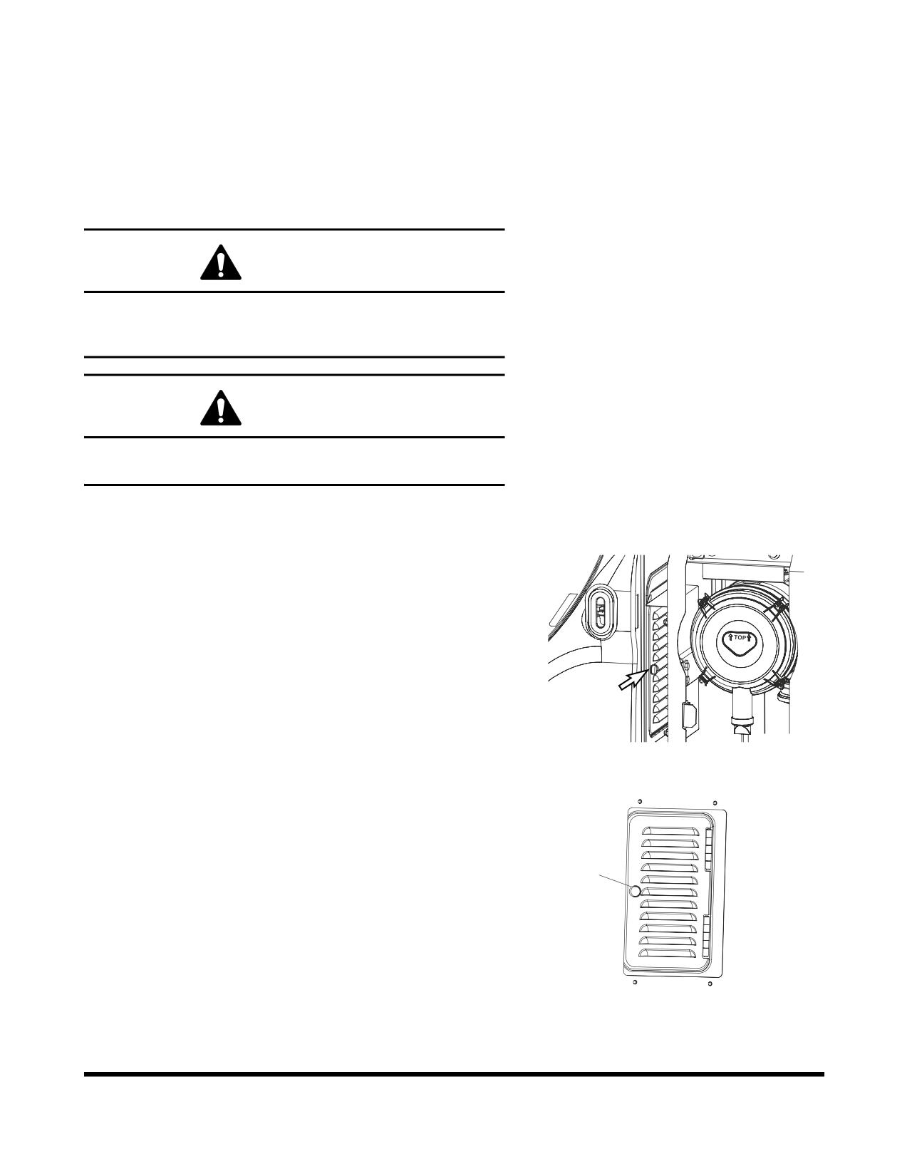
Clean Air-Conditioning Outer Filter
The unit is equipped with an air filtration system which filters out
dirt and dust particles from air being circulated into operator's
cabin. This filter should be cleaned out.
NOTE:
In the event that the unit is being operated in a dusty
environment, the cleaning and replacement should
be performed more frequently. If filter is damaged,
replace damaged filter with a new one.
WARNING!
All service and inspection of air-conditioning system
should be performed with the starter switch in the "O"
(OFF) position.
WARNING!
If using compressed air to clean the element, make sure
that proper eye protection is worn.
NOTE:
All right and left call outs are based on the operator
being seated in the operator's seat facing the front.
1.
Open the door in the left of the machine.
Doosan
FG009578
Figure 55
2.
Open the cover by turning the knob (1, Figure 56) in the
rear of the cabin.
1
FG000441
Figure 56
Inspection, Maintenance and Adjustment
OP000599
4-38
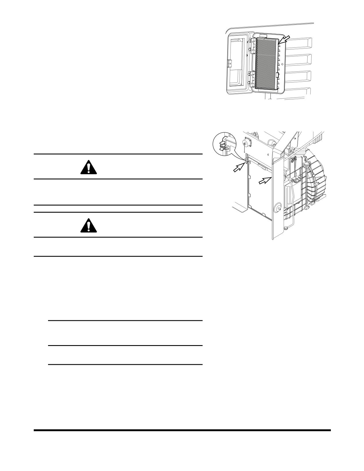
3.
Remove filter (Figure 57) and inspect for any damage.
4.
Use compressed air to clean filter. If filter is still dirty, then
change to new one.
5.
Reassemble in reverse order.
FG000342
Figure 57
Check and Clean Air-Conditioning Inner
Filter
WARNING!
All service and inspection of air-conditioning system
should be performed with the starter switch in the "O"
(OFF) position.
WARNING!
FG000422
If using compressed air to clean the element, make sure
Figure 58
that proper eye protection is worn.
1.
Remove the filter by pulling out ward the knob while
pressing the upper part and lower part of the filter handle
which is inside of the left rear part of the cabin.
2.
Use compressed air in the clean filter. If the filter is
damaged replaced by a new one.
If the filter is very dirty use a mild soap or detergent and
water to clean it.
IMPORTANT
If water was used to clean filter, be certain it is
completely dry before installing.
OP000599
Inspection, Maintenance and Adjustment
4-39
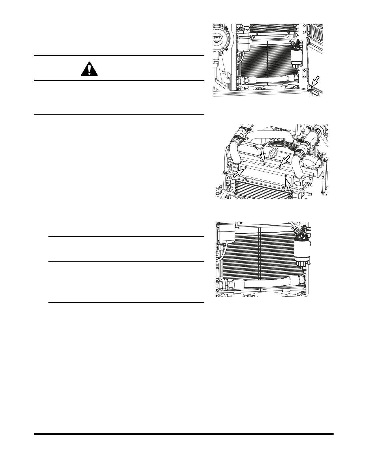
Clean Radiator, Oil Cooler, Intercooler,
Fuel Cooler and Air Conditioner
Condenser Core
WARNING!
If compressed air, steam or water hit your body directly,
there is danger of injury. Always wear protective glasses,
FG009572
mask and safety shoes during the cleaning precess. Make
Figure 59
sure that all extra personnel are clear of the work area.
1.
Open the rear left door and engine cover.
2.
Loosen the wing bolt(s) and remove dust net from in front
of oil cooler and intercooler.
3.
Clean the outside of the radiator and oil cooler, intercooler
and fuel cooler with compressed air, steam or water. Wash
from the outside of the engine compartment inwards.
Repeat the cleaning process from the inside of the engine
compartment outwards to remove all dirt and debris.
NOTE:
Clean dust net and install it after cleaning
radiator, oil cooler, intercooler and fuel cooler.
FG009573
Figure 60
4.
Clean air conditioner condenser core with compressed air,
steam or water.
IMPORTANT
To prevent damage to the cores, apply compressed air
from an appropriated distance. Damaged core may
cause water leakage or overheating. In a dusty site,
check the core daily, irrespective of the maintenance
interval.
FG009574
Figure 61
Inspection, Maintenance and Adjustment
OP000599
4-40
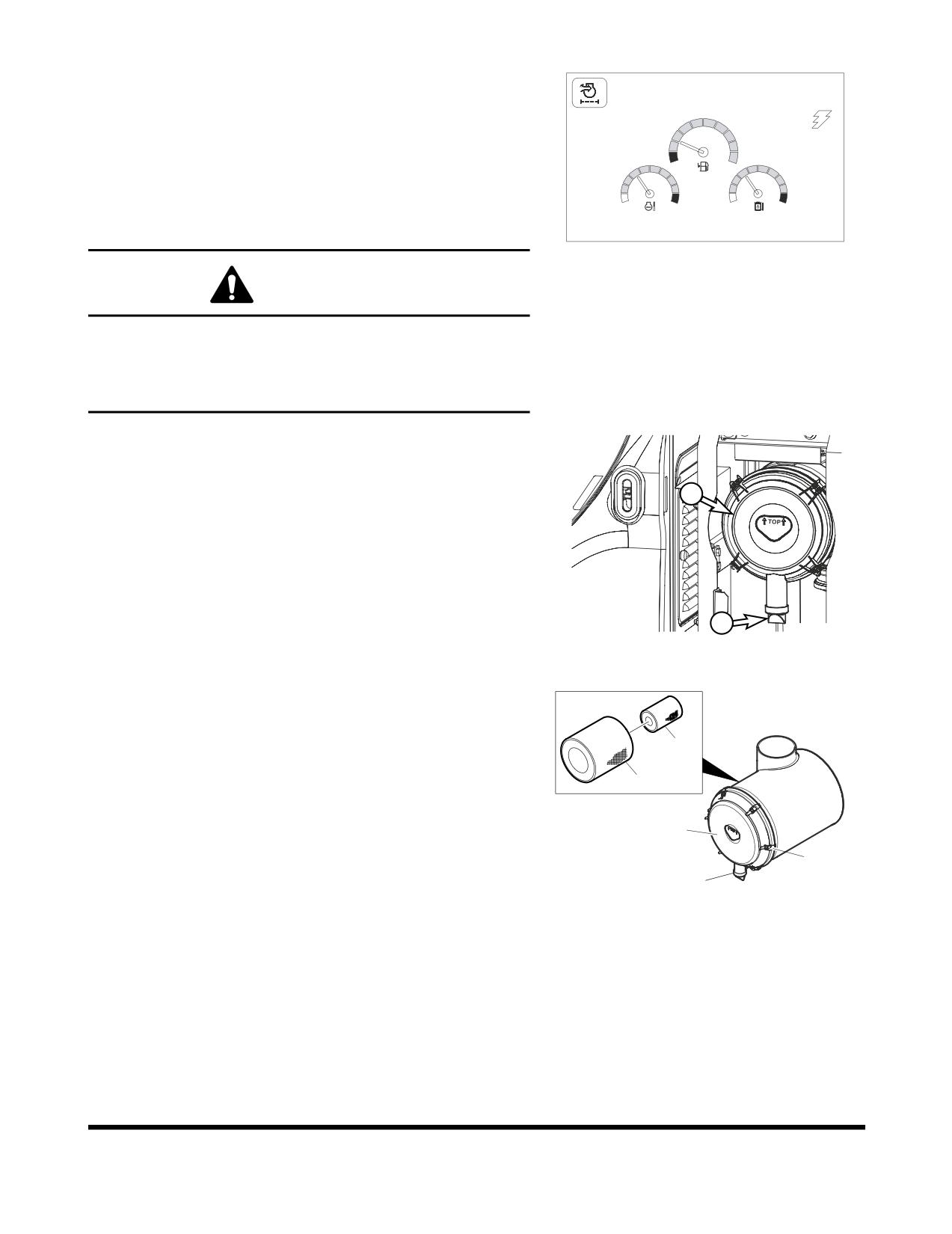
Clean Outer Filter of Air Cleaner
02/05 [MO] 11:30
NOTE:
Clean outer filter every 500 hours / 3 months of
service.
NOTE:
If air cleaner clogged warning light (Figure 62) on
instrument panel comes "ON" the air cleaner must be
E
F
serviced.
C
H
C
H
NOTE:
When working in severely dusty conditions, the
service interval should be shortened.
E/G SPEED 1700 RPM
FG000264
Figure 62
WARNING!
Never clean or attempt to remove the air cleaner filter if the
engine is running.
If using compressed air to clean the filter, make sure that
proper eye protection is worn.
1.
Locate the air cleaner assembly.
NOTE:
When it reaches every 500 hours or If indicator
light (Figure 62) on instrument panel comes
2
"ON" the air cleaner must be serviced.
NOTE:
Replace outer filter after cleaning 5 times or
Doosan
every 2,000 hours / 1 year of service.
2.
Remove and clean rubber evacuator valve (1, Figure 63)
from bottom of air cleaner housing cover (2). Inspect seal
lips for wear or damage. Replace valve if necessary.
1
FG009575
NOTE:
Install evacuator valve with lips parallel to the
Figure 63
cover.
3.
Remove the access cover (2, Figure 64) by loosening the
latches (3).
4.
Remove the outer filter (4, Figure 64) from the housing. Do
5
not remove inner filter (5).
4
2
3
1
FG000702
Figure 64
OP000599
Inspection, Maintenance and Adjustment
4-41
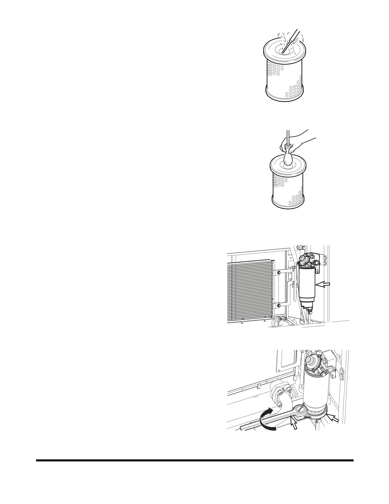
5.
Clean the outer filter (4, Figure 64) by blowing compressed
air from the inside of the filter towards the outside. Do not
use more than 205 kPa (30 psi) air pressure.
HAOC570L
Figure 65
6.
Check outer filter by shinning a light through it. If small
holes or thinner parts are found on the element after
cleaning it, replace the filter.
7.
Clean the inside of the air cleaner body and the inside of
the air cleaner cover. Do not use compressed air.
8.
Properly install the air filter and cover.
9.
After filter service be sure to install cover with arrows
pointing "UP."
NOTE:
If after cleaning the outer filter, the air cleaner
FG000412
clogged indicator remains "ON," replace the
Figure 66
outer and inner filters. Do not clean inner filter.
Change of Fuel Prefilter
1.
Open the left rear side door to access fuel prefilter.
2.
Position a small container under prefilter. Drain fuel by
opening drain valve on bottom of filter.
NOTE:
Dispose of drained fluids according to local
regulations.
FG000413
Figure 67
3.
Remove the bowl using supplied tool.
4.
Remove the cartridge.
FG000436
Figure 68
Inspection, Maintenance and Adjustment
OP000599
4-42