Doosan DX140LC. Operation and Maintenance Manual (2007) - page 5
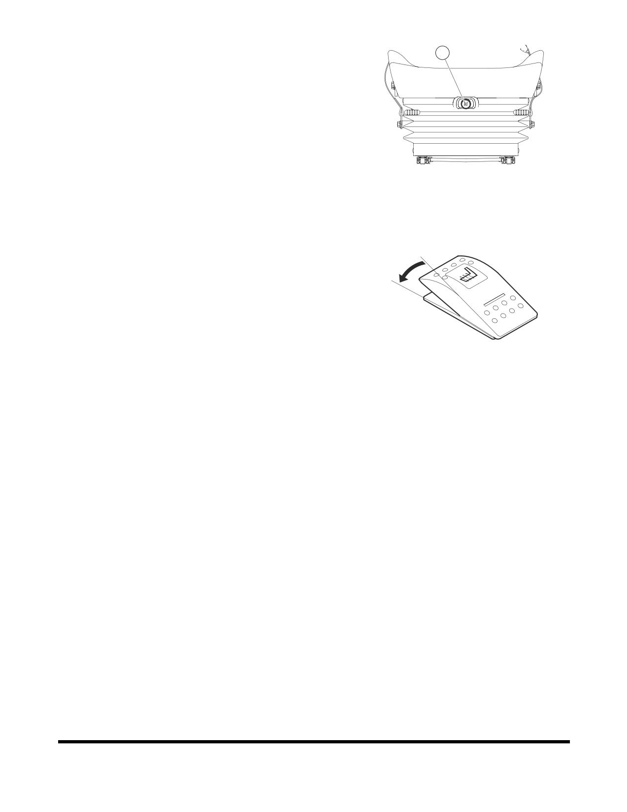
12. Air Suspension Seat (Optional)
12
The operator seat is also available with air suspension for
even better comfort. The switch (12, Figure 134) in the
middle of the seat can be used to adjust the air cushion. If
the switch is pressed, the seat become harder, and pulling
it out makes the seat softer, when the air is bleed out.
FG000187
Figure 134
13. Heating the Operator's Seat (Optional)
The air suspension seat can be heated. The switch on the
O
left control stand is used to warm the seat. When heating is
not needed or seat is warmed, turn the switch to "OFF"
I
position.
FG000034
Figure 135
Operating Controls
OP000597
2-64
CEILING COVER
NOTE:
If the machine is equipped with the optional
transparent ceiling cover never use any chemical
cleaners on its surface. Only use warm water to wash
dust and dirt from its surfaces, and after that, dry it
with a soft fabric towel.
FG000189
Figure 136
Opening the Ceiling Cover
1.
Lower bucket to ground.
2.
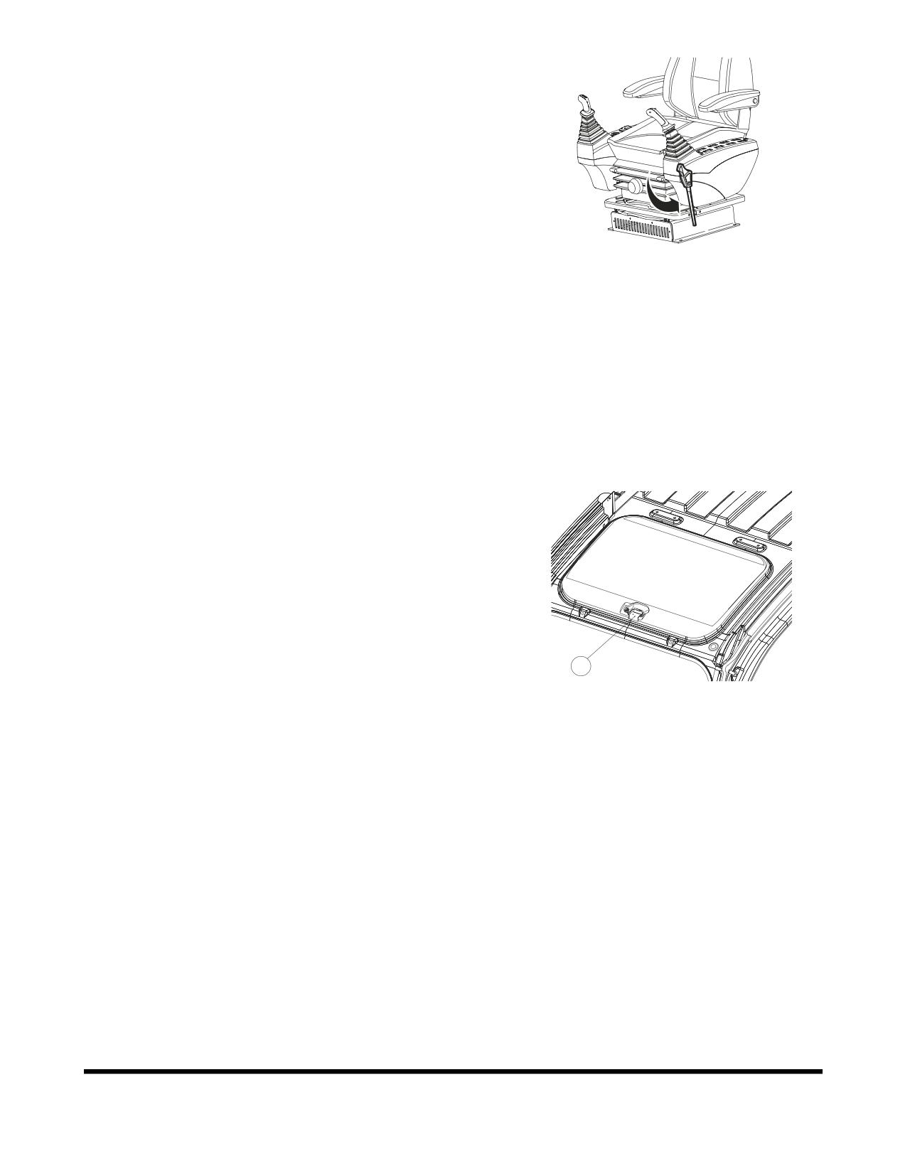
Set safety lever (Figure 136) on "LOCK."
3.
Pull the lock (1, Figure 137) in front center of ceiling cover
and push it up with handle.
Closing the Ceiling Cover
1.
Lower bucket to ground.
2.
Set safety lever (Figure 136) on "LOCK."
3.
Pull down cover with the handle (Figure 137) so that the
lock (1) can be locked in the bracket in the ceiling frame.
1
FG000190
Figure 137
OP000597
Operating Controls
2-65
FRONT WINDOWS
WARNING!
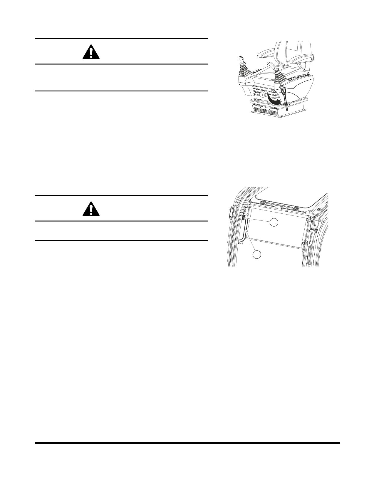
When leaving operator's seat, set the safety lever to
"LOCK" position (Figure 138), if not a serious accident
could occur by accidentally moving the work levers.
FG000189
Figure 138
Front Upper Window
The front upper window can be housed in the cabin's ceiling.
Opening the Window
WARNING!
2
When stowing front window in the cabin roof, make sure
both release levers (1, Figure 139) are latched.
1.
Lower bucket to ground.
1
2.
Set safety lever (Figure 138) on "LOCK."
FG000192
3.
Set engine speed control dial to "LOW IDLE." Allow engine
Figure 139
to idle for three - five minutes.
4.
Shut down engine by turning key to "O" (OFF) position.
5.
Hold the window handles (1, Figure 139), then pull the lock
levers (2) to release the lock. The top of the front window
will come out.
6.
Pull window up, and push it against lock pin at the rear of
the cabin. Make sure that it is securely latched.
7.
Check that lock levers are securely latched in the lock
position.
NOTE:
When the front upper window is open, never
extend your head or body through the window
frame.
NOTE:
If the window happens to fall with a strong
impact against the machine, while some part of
your body is extended out of the cabin, it may
result in bodily injury.
Operating Controls
OP000597
2-66
Closing the Window
WARNING!
Be careful that your hands are not caught in window frame.
1.
Lower bucket to ground.
2.
Set safety lever (Figure 138) on "LOCK," and shut down
1
2
engine.
FG000193
3.
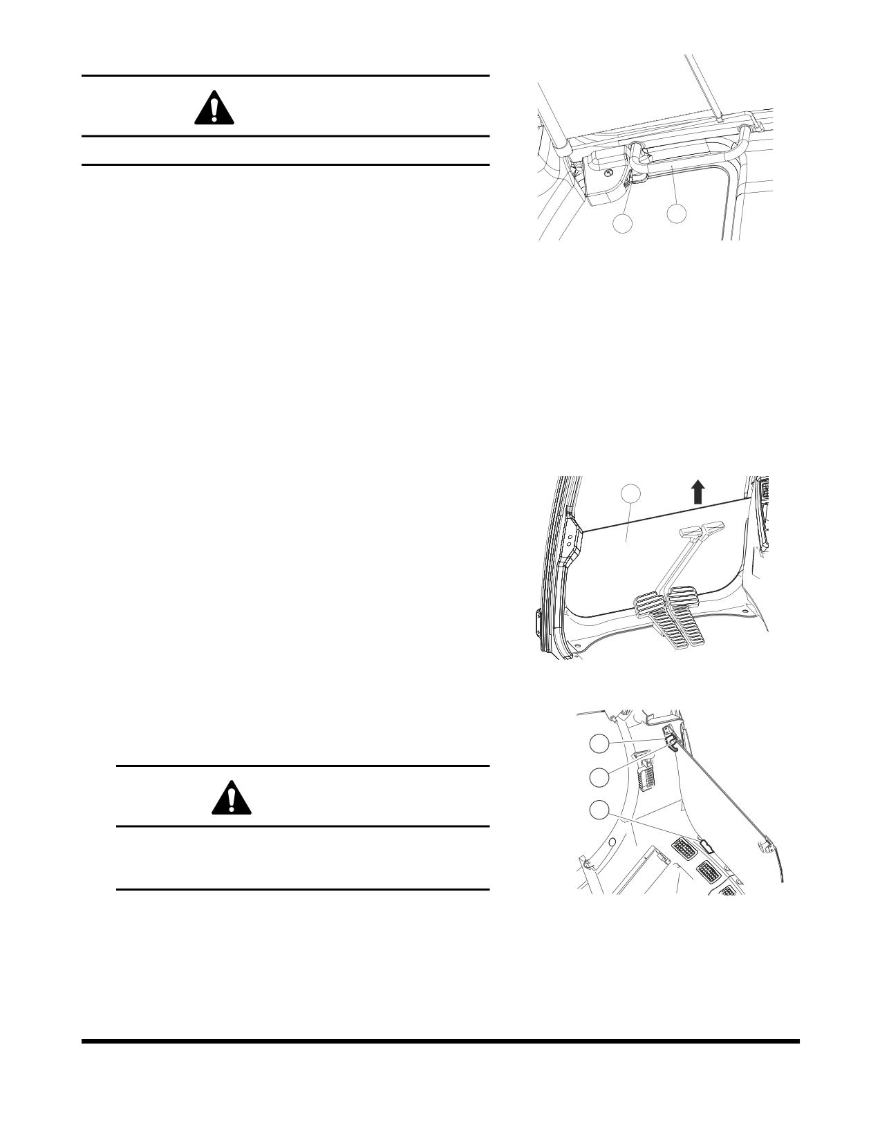
Holding upper handles (1, Figure 140) of front window with
Figure 140
left and right-hand, pull lock levers (2, Figure 140) to
release the lock.
4.
Push window forward, and lower it slowly.
5.
When the bottom of the window, reaches the top of the
front bottom window, push the front window to engage the
lock (2, Figure 139).
6.
Check that lock levers are securely latched in the lock
position.
Front Bottom Window
1
The front bottom window can be removed and stored in the rear
of the cabin.
1.
After stowing the front upper window in the cabin ceiling,
remove bottom window (1, Figure 141) from cabin in
direction of the arrow.
FG000194
Figure 141
2.
Set bottom window in rubber holders (2, Figure
142)
behind operator's seat. Secure window with left and right
knobs (3) with push button (4).
3
4
WARNING!
2
Never have wet hands when handling a window. Never
drop window or let it come into contact with other
parts of the machine.
FG001345
Figure 142
OP000597
Operating Controls
2-67
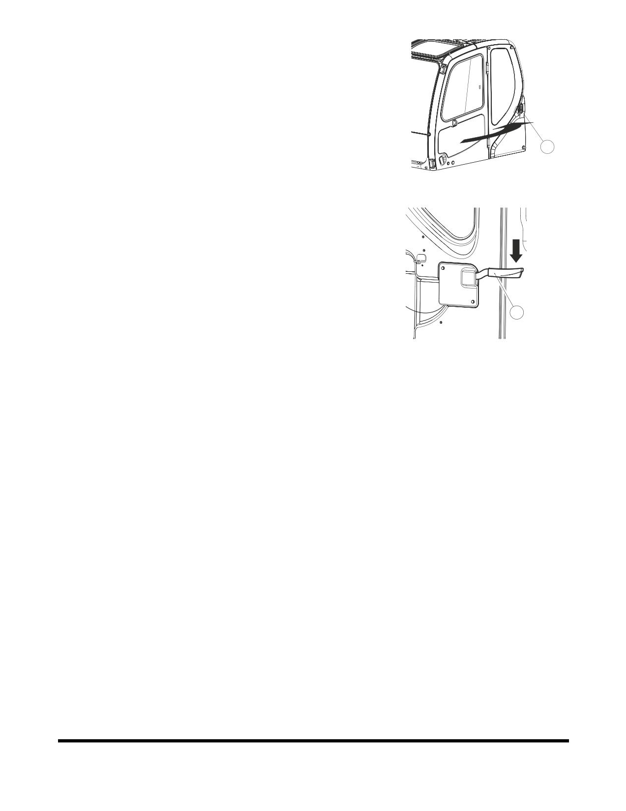
DOOR SIDE LATCH
1.
The door side latch (1, Figure 143) is used to secured the
door to the side of the cabin when it is opened.
NOTE:
Keep the door closed and locked when machine
is not in use.
1
FG000196
Figure 143
2.
To release door from side of cabin, push the latch lever (2,
Figure 144) down. The latch lever is to the left of the
operator's seat.
2
FG000673
Figure 144
Operating Controls
OP000597
2-68
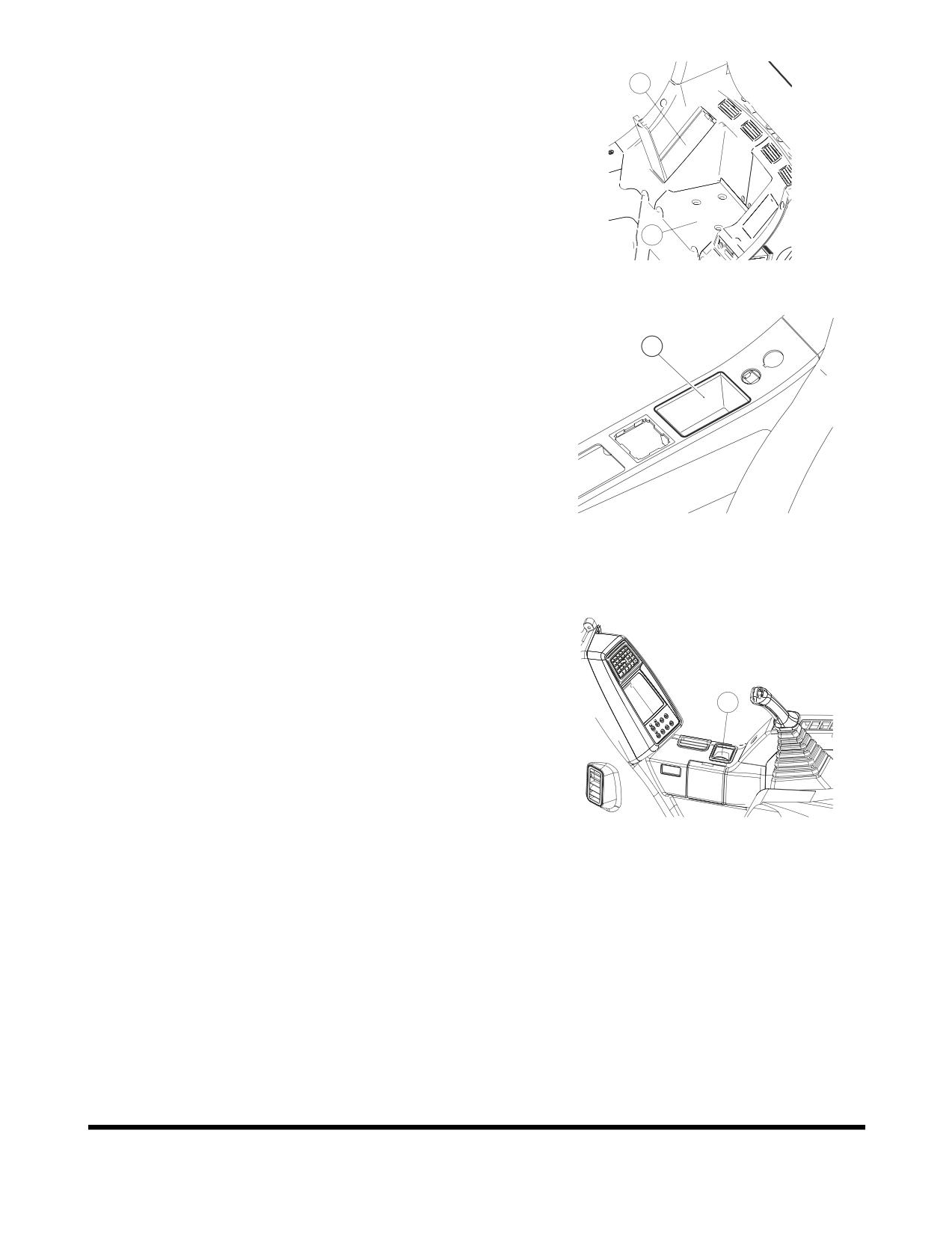
CABIN STORAGE
2
COMPARTMENTS
There are two storage compartments behind the operator's seat.
The large compartment
(1, Figure
145) is for storing
nonperishable items.
The covered other one (2, Figure 145) is interconnected with the
air conditioner. So, it can be supplied with either warm or cool air
1
when air conditioner is turned "ON."
FG000209
Figure 145
There is a separate small tray (3, Figure 146) on the right side of
operator's seat.
3
FG000675
Figure 146
ASHTRAY
An ashtray (1, Figure 147) is to the right side of the operator's
seat on the side of the cabin. Always close ashtray after putting
out a cigarette.
1
FG000200
Figure 147
OP000597
Operating Controls
2-69
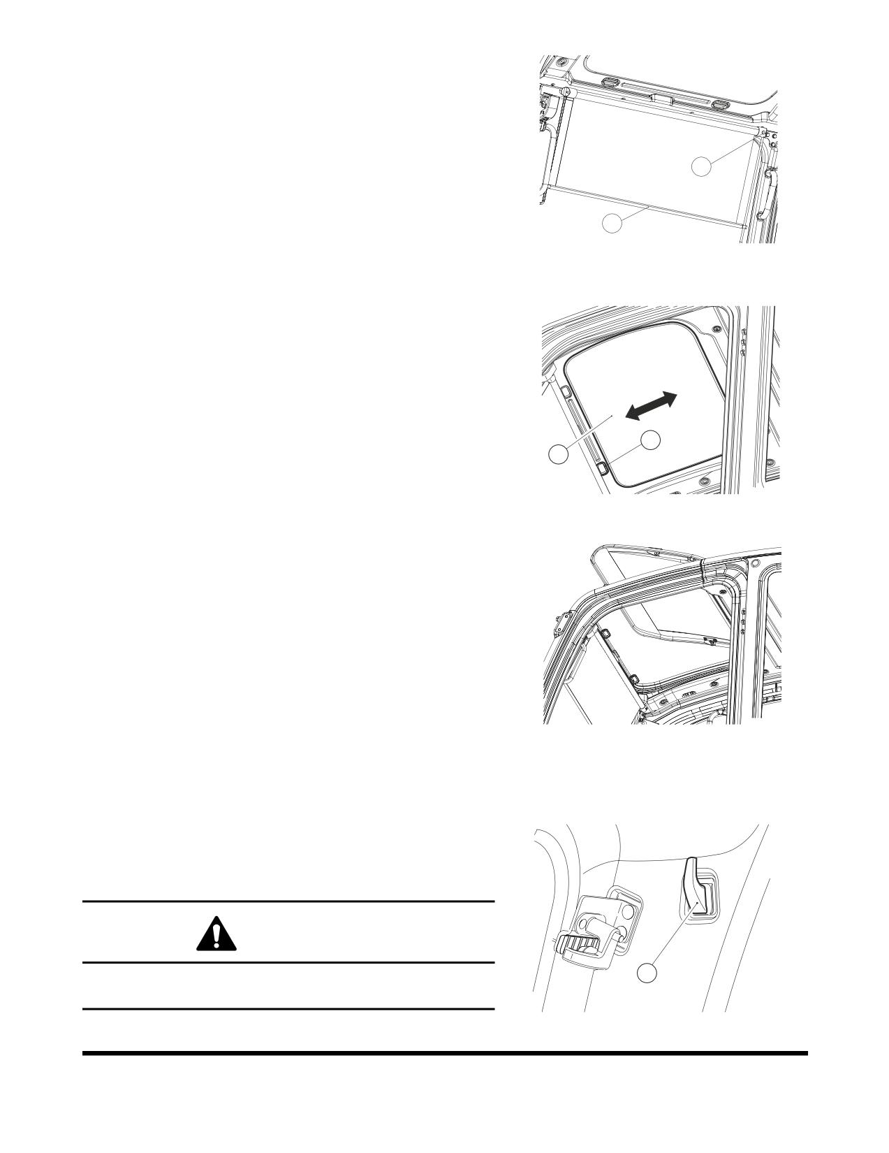
SUN VISOR
The sun visor can be used to reduce the amount of sunlight
coming through the front window and ceiling.
When wanting to reduce the amount of sunlight coming in the
front window, pull bar (1, Figure 148) down.
2
When not wanting protection, hold the bar with left-hand and
push the release button (2, Figure 148) with right-hand. This will
allow the visor to retract.
1
F
G0
00201
NOTE:
Do not allow the visor to roll back up without holding
Figure 148
it. Not holding it may result in damage to the visor and
retract mechanism.
Ceiling sun visor
(3, Figure
149) slides forward and
backwards.Move it with handle (4) on each side.
4
3
FG000676
Figure 149
When opening the ceiling cover (if equipped), push the sun visor
into its compartment (Figure 150).
FG000204
Figure 150
HANGER
A hanger (1, Figure 151) is located on the upper left side of the
operator's compartment.
WARNING!
1
Do not hang anything that will easily fall down, or will
impair your view out of the cabin.
FG000210
Figure 151
Operating Controls
OP000597
2-70
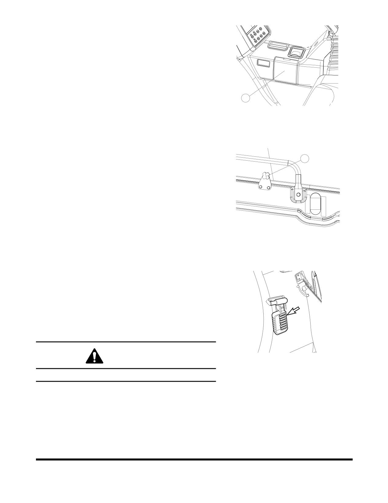
CUP HOLDER
There is a cup holder on the right side of the compartment (1,
Figure 152). Open the access cover and lower it to a horizontal
position.
1
FG000205
Figure 152
DOOR WINDOW HOLDER
1
When the machine is being operated with the cabin door window
opened, window vibration can be reduced by tightening knob (1,
Figure 153) against the window.
FG000206
Figure 153
EMERGENCY GLASS BREAKING
TOOL
The excavator is equipped with a glass breaking tool. It is to the
upper right corner of the cabin. This tool can be used in case of
an emergency situation which requires the breaking of glass to
exit from the cabin. Grip the handle firmly and use the sharp
point to break the glass.
FG000178
WARNING!
Figure 154
Protect your eyes when breaking the glass.
OP000597
Operating Controls
2-71
MISCELLANEOUS ACCESS
COVERS AND DOORS
Side Door
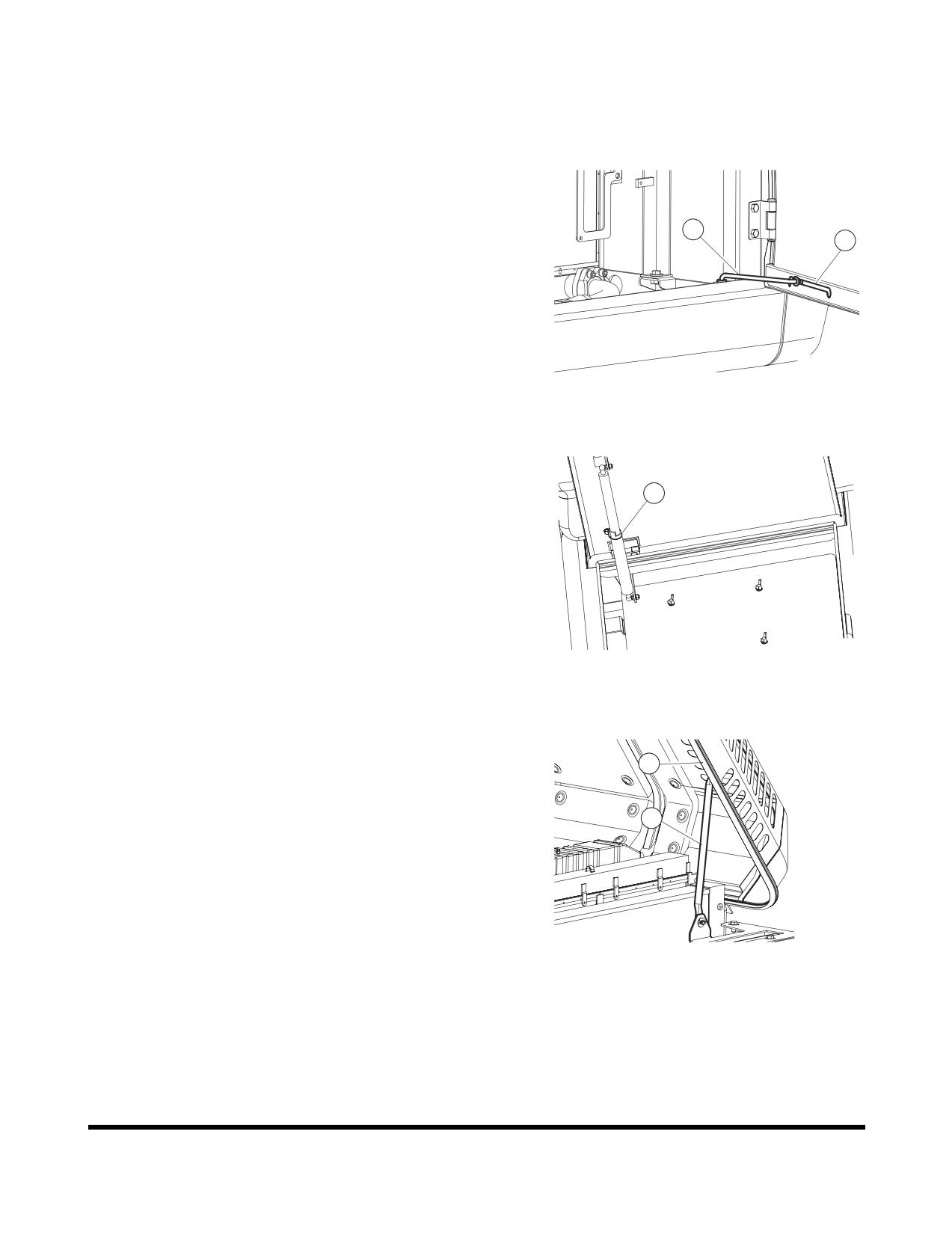
Open the side access door and slide prop rod (1, Figure 155) in
slot (2) until it locks at the end of slot.
1
2
FG000165
Figure 155
Battery Box Door
1
Opening
Open door until locking device (1, Figure 156) latches.
Closing
While holding door, press locking device to release lock and
close door.
FG006301
Figure 156
Engine Cover
2
Open the cover and slide prop rod (1, Figure 157) in the slot (2)
until it locks in notch at the end of slot to support the cover.
1
To close cover, move end of prop rod out of notch so it can slide
in slot.
FG000167
Figure 157
Operating Controls
OP000597
2-72