Doosan DX140LC. Operation and Maintenance Manual (2007) - page 4
5.
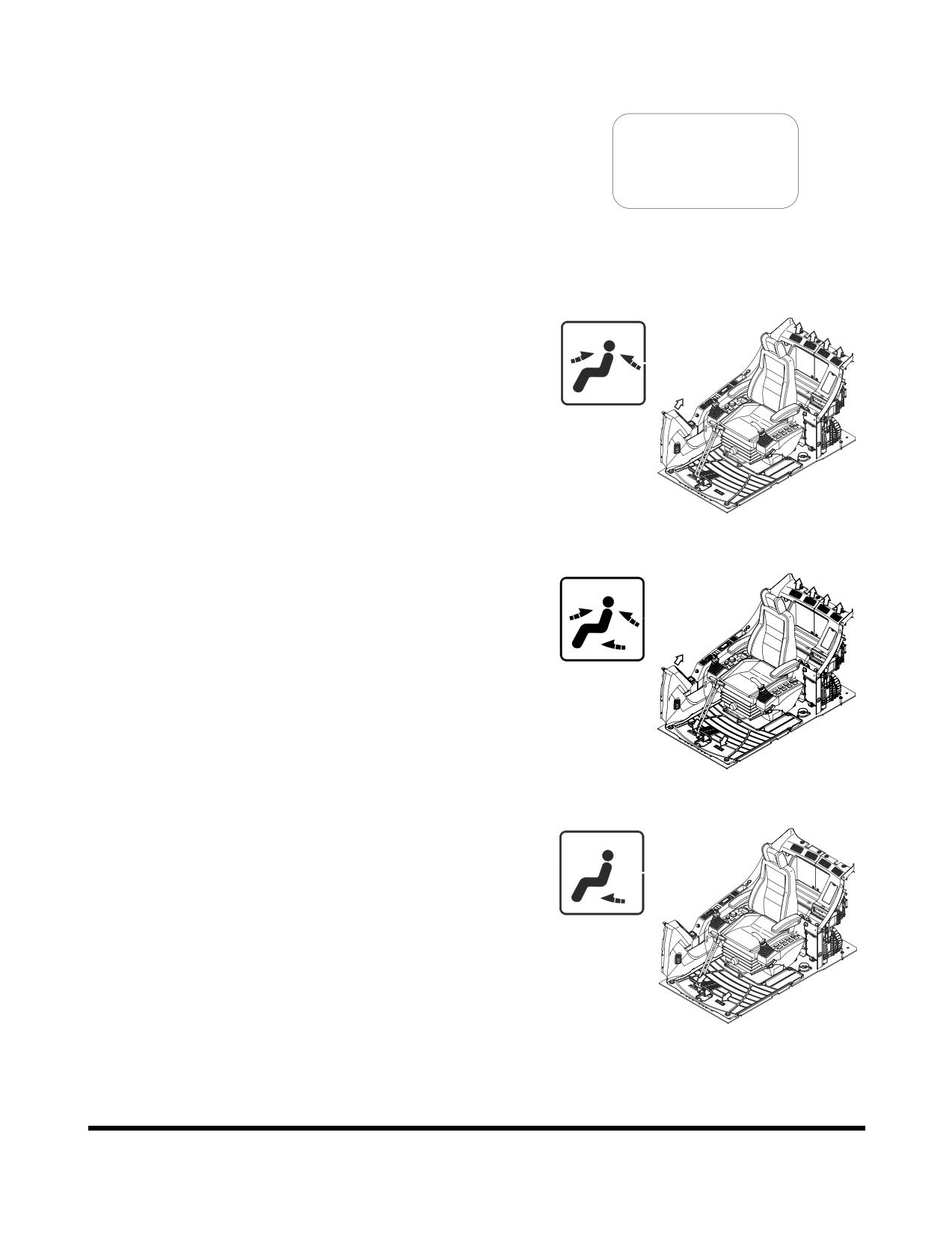
Mode Selector Button
This button is used to select which combination air outlets
will be used.
MODE
FG000096
Figure 111
A.
Used to direct air flow to upper portion of operator's
cabin from both the front and rear.
FG000099
Figure 112
B.
Used to direct air flow to upper portion of operator's
cabin from both the front and rear. It will also deliver
air to the lower portion of operator's cabin from under
the operator's seat.
FG000097
Figure 113
C.
Used to direct air flow to lower portion of operator's
cabin and feet.
This mode is mainly used for heating.
FG000100
Figure 114
Operating Controls
OP000597
2-54
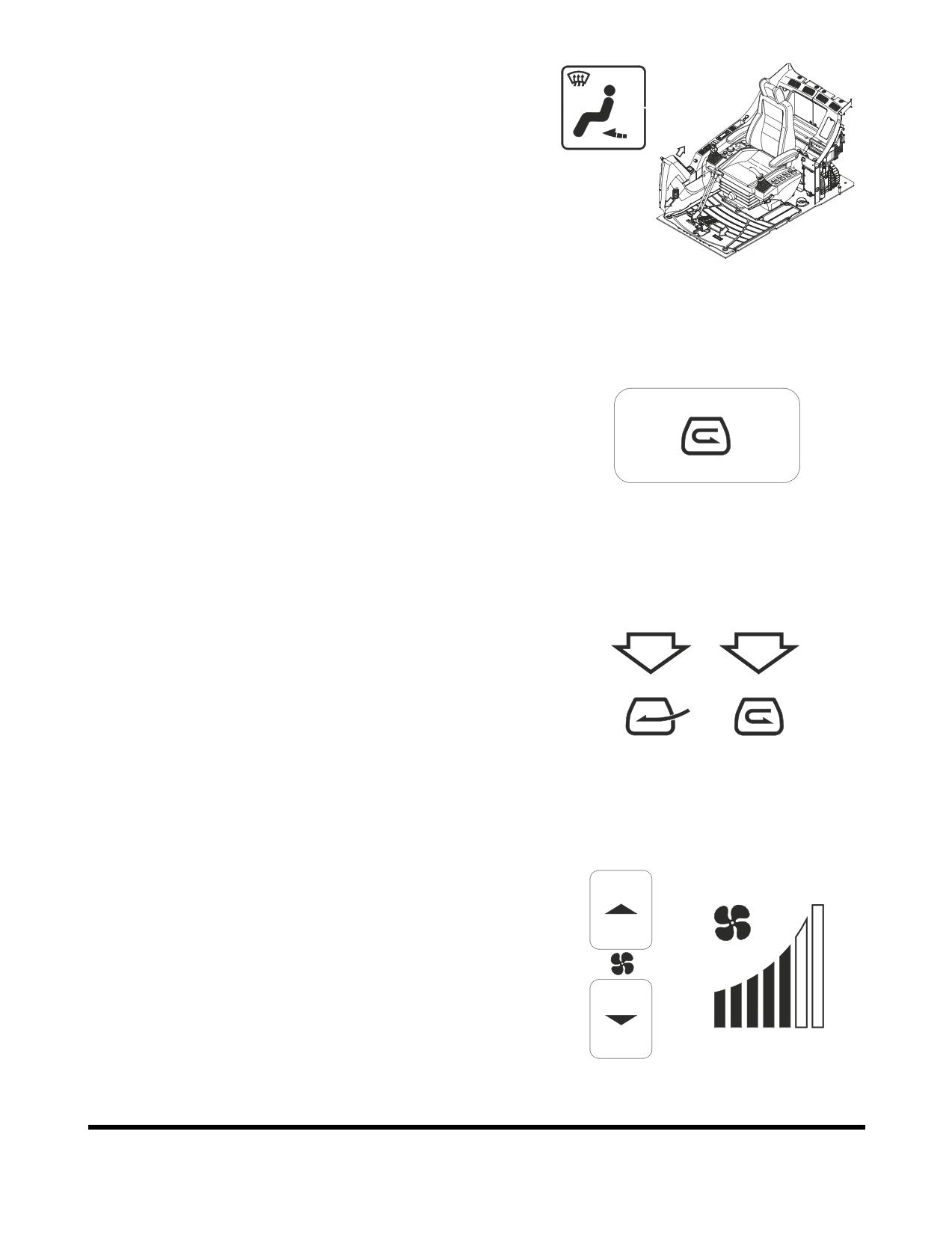
D.
Used to direct air flow to the front window and to
operator's feet.
FG000098
Figure 115
6.
Air Inlet Selector Button
This button is used to select fresh air from outside the
cabin, or recirculate air within the cabin.
Pressing this switch enables the choice between fresh air
and recirculating air within the operator's compartment.
The select mode is displayed on the LCD.
FG000101
Figure 116
A.
"A" Symbol
- Draws fresh air into operator's
compartment. Used to exchange air within the
operator's compartment with fresh air. Used to
remove condensation or ice on window (Winter /
A
B
Rainy Season).
B.
"B" Symbol - Recirculates air within the operator's
compartment. Used to quickly warm or cool the
operator's cabin.
FG000102
Figure 117
7.
Fan Speed Selector Buttons
These buttons are used to control the speed of the blower
fan.
Momentarily, pressing a button, changes the speed one
stage.
Continuously pressing and holding a button, repeatedly
changes the speed.
FG000103
Figure 118
OP000597
Operating Controls
2-55
8.
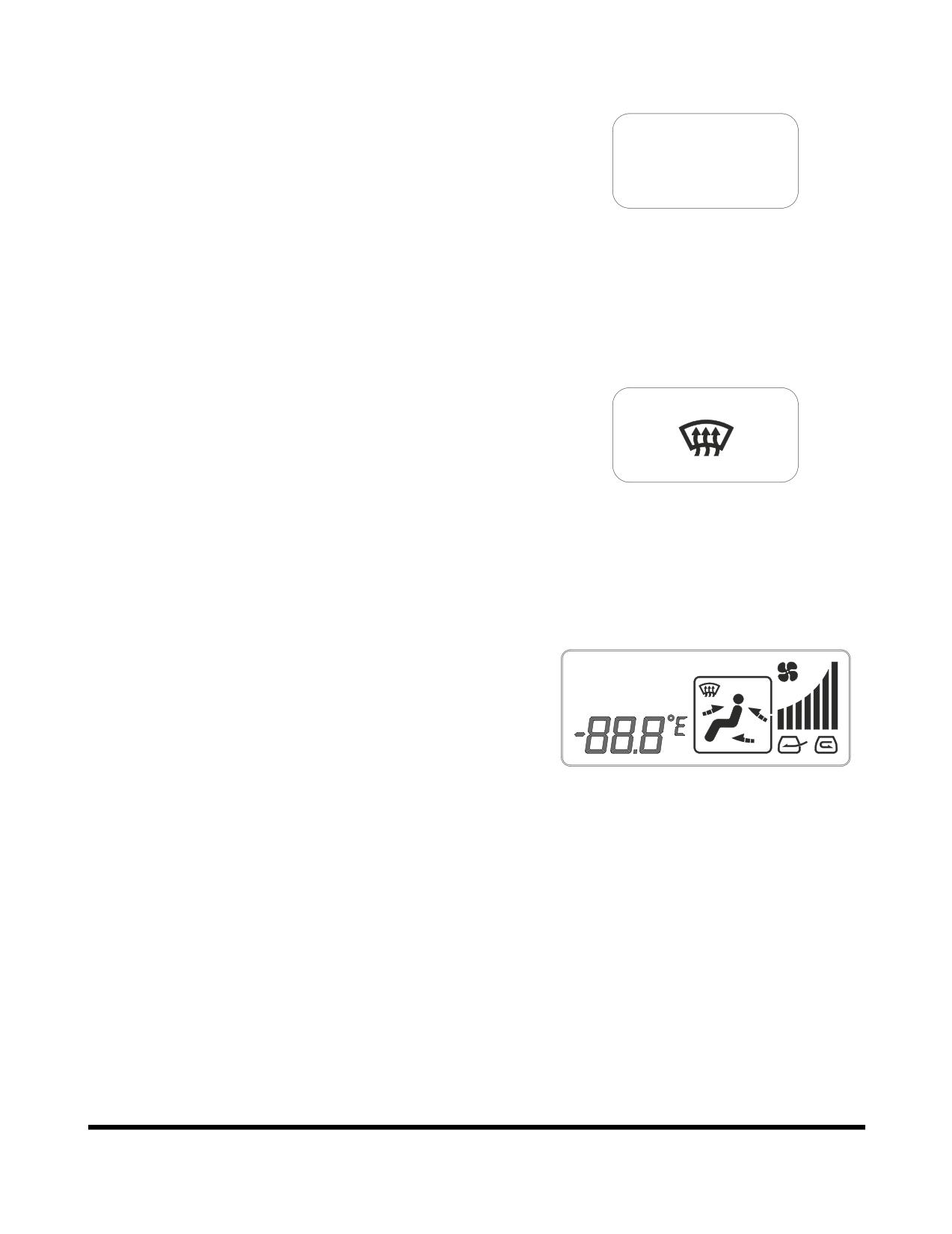
Air Conditioner Button
This button is used to turn the air conditioner "ON" or
"OFF."
When this function is activated, an "A/C" is displayed in the
upper left corner of the LCD.
A/C
FG000105
Figure 119
9.
Defroster Button
Used to direct air flow to front window.
FG000106
Figure 120
10. LCD Display
This display shows the current setting.
A/C
OUTSIDE
AUTO
MAX
Memory Function
The air conditioner panel has a memory function. When the
starter switch is turned "OFF" the settings for the panel, will be
stored. When the excavator is started, the last stored setting will
be used.
FG000107
Figure 121
Additional Operating Instructions
A proper indoor temperature in summer is 5 - 6°C (10 - 12°F)
less than the outdoor temperature.
Operate the air conditioner for twenty - thirty minutes a week to
circulate the refrigerant in the system.
NOTE:
The blower button should be on "Three Bars."
If operating the air conditioner or heater for a long time, operate
the air inlet selector button, and when smoking, vent the air to
the outside to prevent irritation to eyes.
Operating Controls
OP000597
2-56
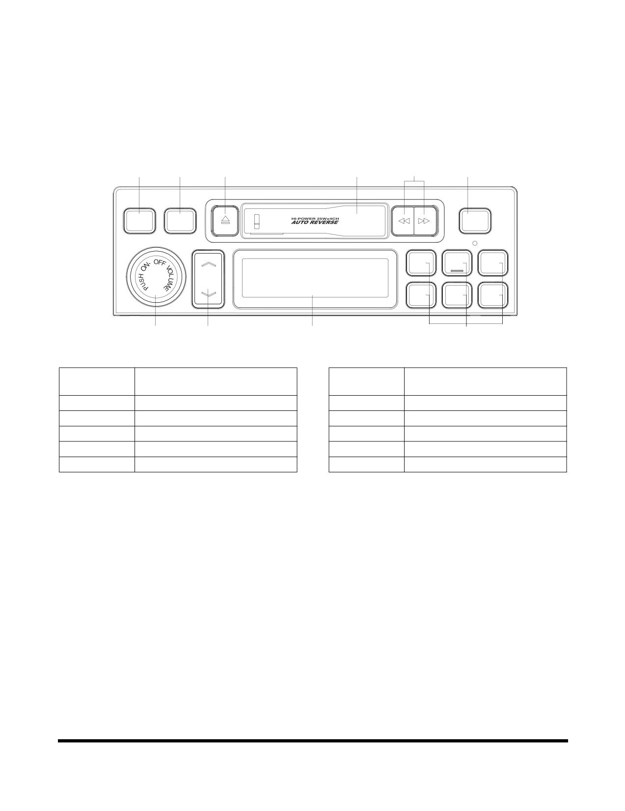
STEREO
Before operating the stereo or CD player, read operation manual
enclosed with stereo.
Stereo
2
3
7
9
8
5
P
ROGRA
M
AST
SOUND
AM/FM
SCAN
1
2
3
TUNE
4
5
6
1
4
10
6
FG000108
Figure 122
Reference
Reference
Description
Description
Number
Number
1
Power / Volume Control
6
Preset Station
2
Sound Mode Selector
7
Tape Ejection
3
Band Selection
8
Fast Forward / Rewind
4
Tuning Up / Down
9
Tape Loading Slot
5
Scan Function / Auto Store
10
LCD
OP000597
Operating Controls
2-57
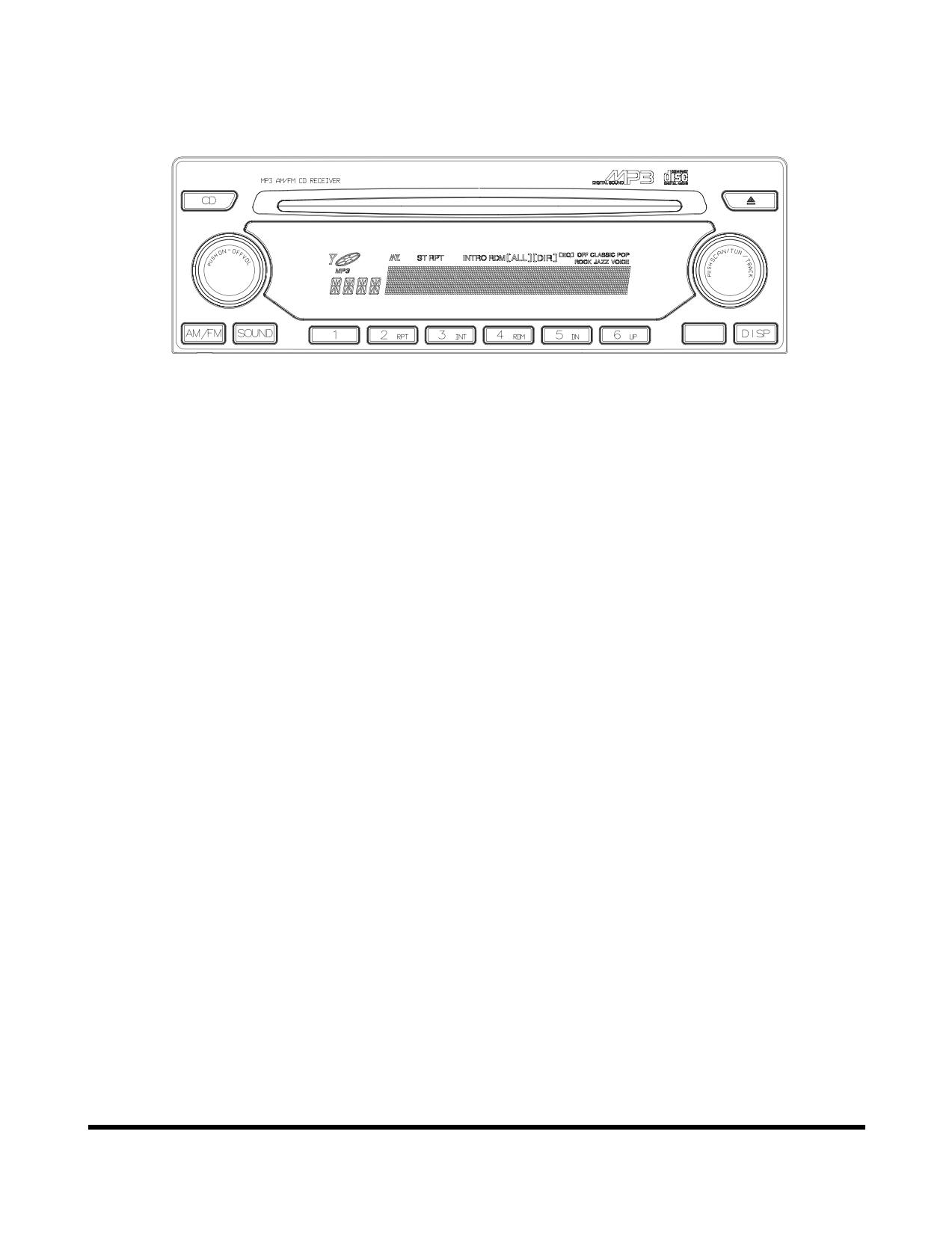
CD Player (Optional)
AST/DIR
FG000109
Figure 123
Operating Controls
OP000597
2-58
MISCELLANEOUS ELECTRICAL
DEVICES
Cabin Light
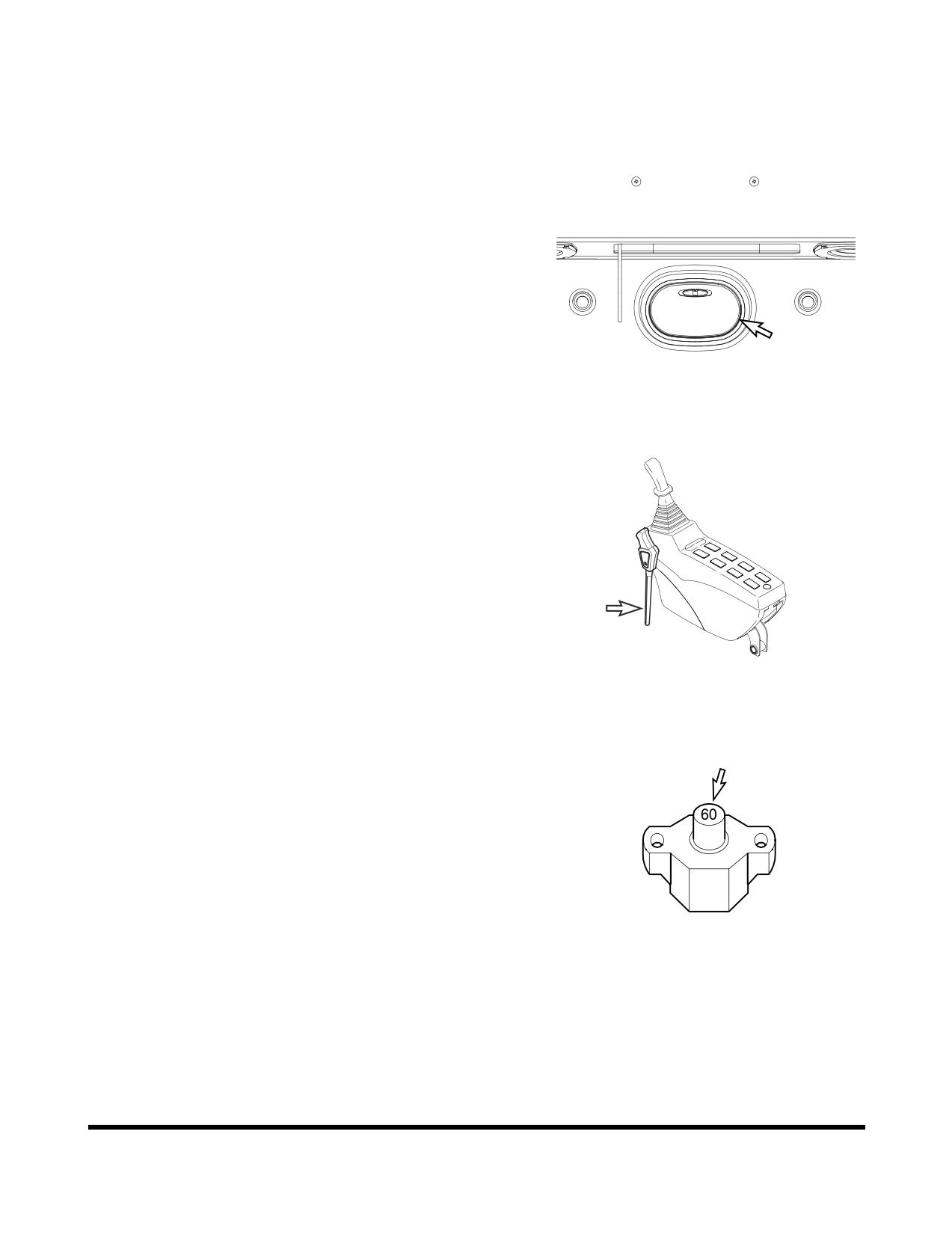
A light is installed on the top of the operator's compartment.
The light will work despite starter switch position.
NOTE:
If light is left "ON" for a long time while the engine is
not running, the battery will be discharged.
FG000417
Figure 124
Pilot Cutoff Switch
When the safety lever is put into the "LOCK" position, the switch
deactivates the work and travel levers. With the work and travel
levers deactivated, no digging/operational work can be done.
FG000211
Figure 125
Circuit Breaker
A main circuit breaker is in the battery box. It will automatically
cut off in case of an electrical short circuit or overload. This will
prevent the electric wiring and components from being burned or
damaged.
If the circuit breaker is cut off, check all related circuits, this
means something is wrong in the electric circuit.
After maintenance, press the red button for normal operation of
circuit breaker.
HAAE2110
Figure 126
OP000597
Operating Controls
2-59
Fusible Link
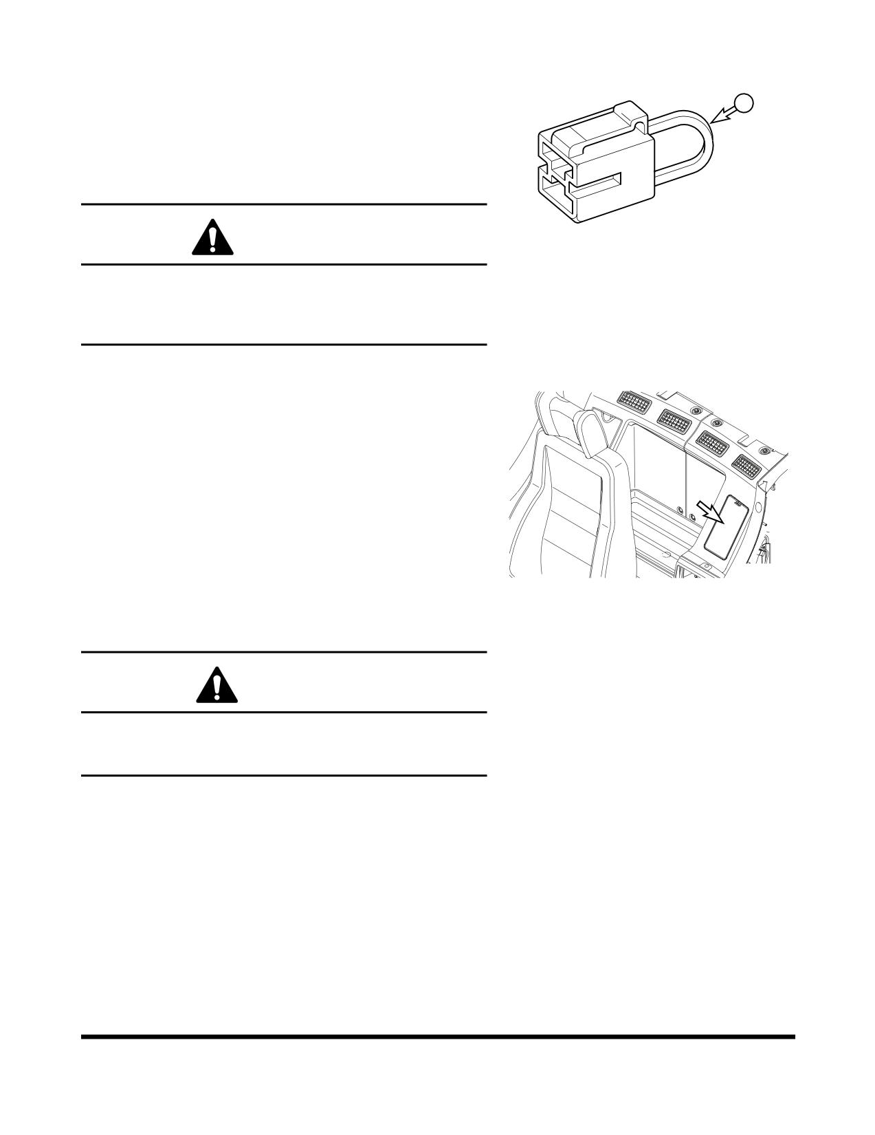
A fusible link is in the battery box.
A
If the engine does not crank, first check that the starter switch is
turned "ON" and that no power is available (No indicator lights
will light.). Check that the "A" portion (Figure 127) of the fusible
link is not broken or burned through. Replace the fusible link if
damage and investigate cause.
HAAE2120
WARNING!
Figure 127
When changing the fusible link, replace the fusible link with
the same capacity part. Otherwise, a fire could break out in
the wiring harness and/or other components of the circuit.
Always use original DOOSAN parts.
Fuse Boxes
There are two fuse boxes (Figure 128) on the left side of the
heater box. The fuses prevent electrical devices from
overloading or shorting.
A decal attached to the inside of the fuse box access cover
indicates the function and amperage of each fuse.
NOTE:
For a further explanation see “Fuse Boxes” on
page 2-60.
Spare fuses are mounted on the inside of fuse box access
FG000110
cover.
Figure 128
Change a fuse if the element separates. If the element of a new
fuse separates, check the circuit and repair the circuit.
CAUTION!
Always replace fuses with the same type and capacity fuse
that was removed. Otherwise, electrical damage could
result.
Operating Controls
OP000597
2-60
SEAT ADJUSTMENT
WARNING!
Adjust the seat position before starting operations or after
changing the operator.
Always fasten your seat belt while operating machine.
Adjust the seat so that the control levers and pedals can be
operated freely and easily with the operator back against
the backrest.
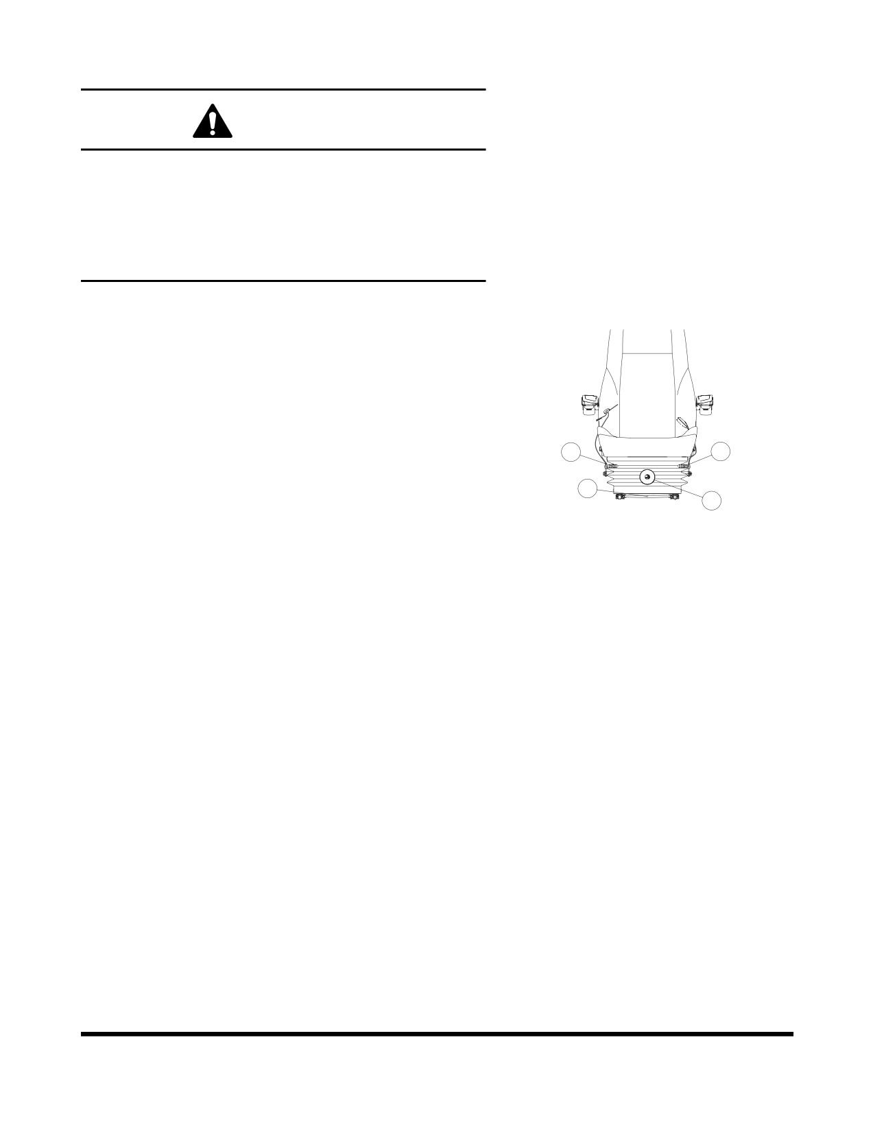
1. Forward / Backward Adjustment
Holding lever (1, Figure 129), raise it up, move the seat to
the desired position. Release lever to lock the seat in the
selected position. Adjustment range is 200 mm (7.9 in).
2. Seat Tilt and Height Adjustment
4
2
1
Forward Tilt
3
FG000183
Push lever (2, Figure 129) down to adjust the angle of the
Figure 129
front of the seat. There are four positions that it can be set
at.
Rear Tilt
Pull lever (2, Figure 129) up to adjust the angle of the rear
of the seat. There are four positions that it can be set at.
Seat Height
It is possible to move the seat up or down by combining
adjustments forward and rear tilt. Adjust the seat according
to operator's size and work conditions. Height adjustment
is 60 mm (2.4 in).
3. Suspension Adjustment
Turning knob
(3, Figure
129) to right makes the
suspension harder. Turning knob to left makes the
suspension softer. Adjust according to operator's weight by
checking the weight indicator dial. Adjustment range is
from 50 - 120 kg (110 - 265 lb).
OP000597
Operating Controls
2-61
4. Reclining Position Adjustment
Pulling up the right lever (4,Figure 129) allows the seat
backrest to be moved forward or backward.
Sit with your back against the seat back when adjusting it.
If your back is not touching the seat back, the seat back
may suddenly move forward.
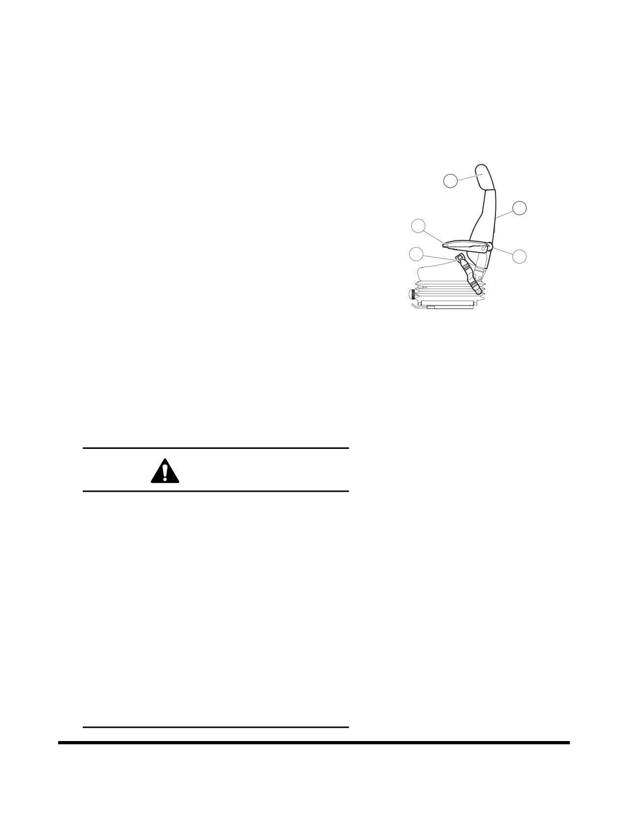
5. Armrest Angle Adjustment
The angle of each armrest can be adjusted by turning a
7
dial (5, Figure 130) on bottom of armrest. When adjusting
the angle, manually raise the armrest before turning the
9
dial.
5
8
6
6. Lumbar Support Adjustment
A lumbar support is located in the seat back.
Turn the dial (6, Figure 130) counterclockwise to increase
FG000778
the force of the lumbar support
Figure 130
7. Headrest
The headrest (7, Figure 130) can be adjusted forward/
backward and up/down. Move it by holding both sides.
8. Seat Belt
WARNING!
The seat belt is for the operator's safety and should
always be worn. Before driving the machine, adjust the
seat to the desired position for maximum comfort and
machine control, then fasten the seat belt. Seat belts
must be worn across the pelvic region and adjusted
snugly to lessen the chance and severity of injury in
case of an accident. Never fasten a seat belt across the
abdomen.
Under no circumstances should the operator be
standing in the cabin when operating the excavator.
Do not adjust the seat position while the vehicle is
moving because a loss of control may result. Stop the
machine, apply the parking brake, and then adjust the
seat.
Always, check the condition of seat belt and belt
bracket before fastening it. Do not use it with twists in
it. Replace belt or bracket if damaged or worn.
Operating Controls
OP000597
2-62
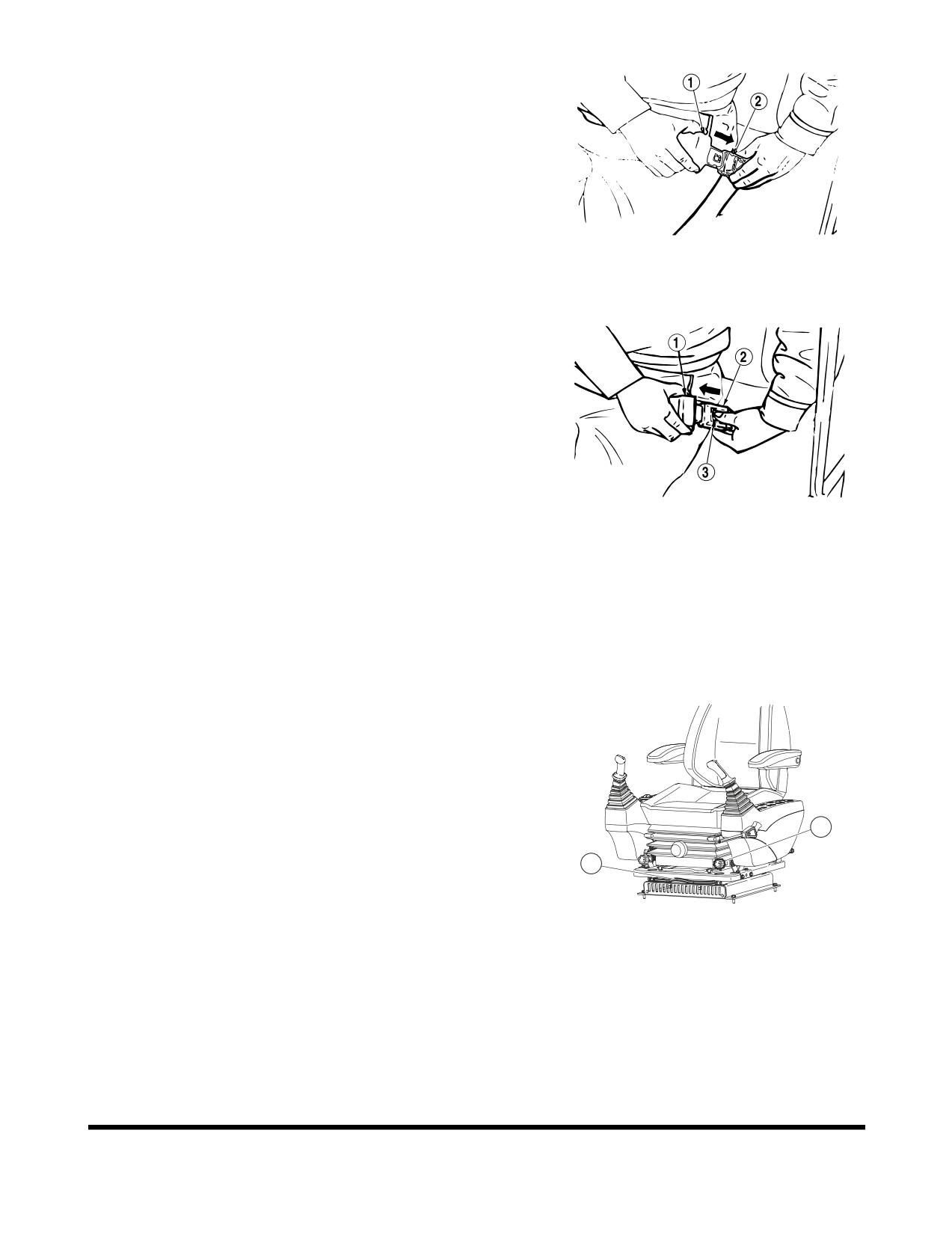
Seat Belt Locking and Unlocking
Insert belt end (1, Figure 131) into the buckle (2). Pull the
belt to check that belt end is locked into buckle.
Adjust belt length so that it comfortably tight against the
operator's pelvic region (hipbone).
HAOB140L
Figure 131
Press the button (3, Figure 132) in the center of buckle (2)
and pull out belt (1) to unlock.
HAOB150L
Figure 132
9. Seat Back-pocket
The seat has a seat back pocket. It is used for storing the
operation and maintenance manual.
10. Left and Right Control Stand
Adjustment
For operator's convenience, the right and left control
stands and seat can slide together, within a 160 mm
(6.3 in) forward or backward travel distance.
Holding lever (10, Figure 133), raise it up, set the seat to
11
desired position. Release lever to lock the seat in the
selected position.
10
FG000185
Figure 133
11. Left and Right Control Stand Height
Adjustment
The left and right dials (11, Figure 133) at the lower part of
the seat can be turned to adjust the elevation height of
each control stand.
It can be used to adjust the height of the control joystick.
OP000597
Operating Controls
2-63