Doosan DX140LC. Operation and Maintenance Manual (2007) - page 2
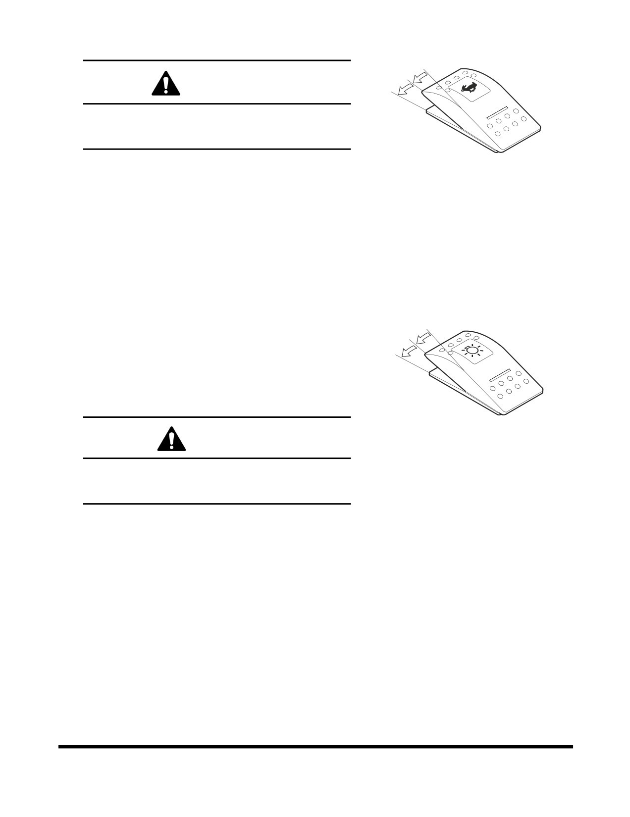
7. Travel Speed Selector Switch
O
I
WARNING!
II
Do not operate the travel speed selector switch when
unit is in motion. Temporary loss of control could
result.
This switch activates the automatic speed range for travel.
FG000023
O. In this position, "LOW" travel speed is selected.
Figure 14
I.
In this position, "HIGH" travel speed is selected.
II.
In this position, "AUTOMATIC" travel speed is
selected. The travel speed automatically changes
between "LOW" or "HIGH" range, depending on
engine speed and travel motor loads.
8. Light Switch
This switch is used to turn "ON" the lights.
O
I
O. In this position, all lights are "OFF."
II
I.
In this position, all illumination lights of the instrument
panel and the control switches are turned "ON."
II.
In this position, all illumination lights and work lights
are turned "ON."
FG000024
CAUTION!
Figure 15
Do not leave instrument panel or work lights "ON"
when the engine is not running. Leaving lights "ON"
with the engine shut down will discharge batteries.
Operating Controls
OP000597
2-14
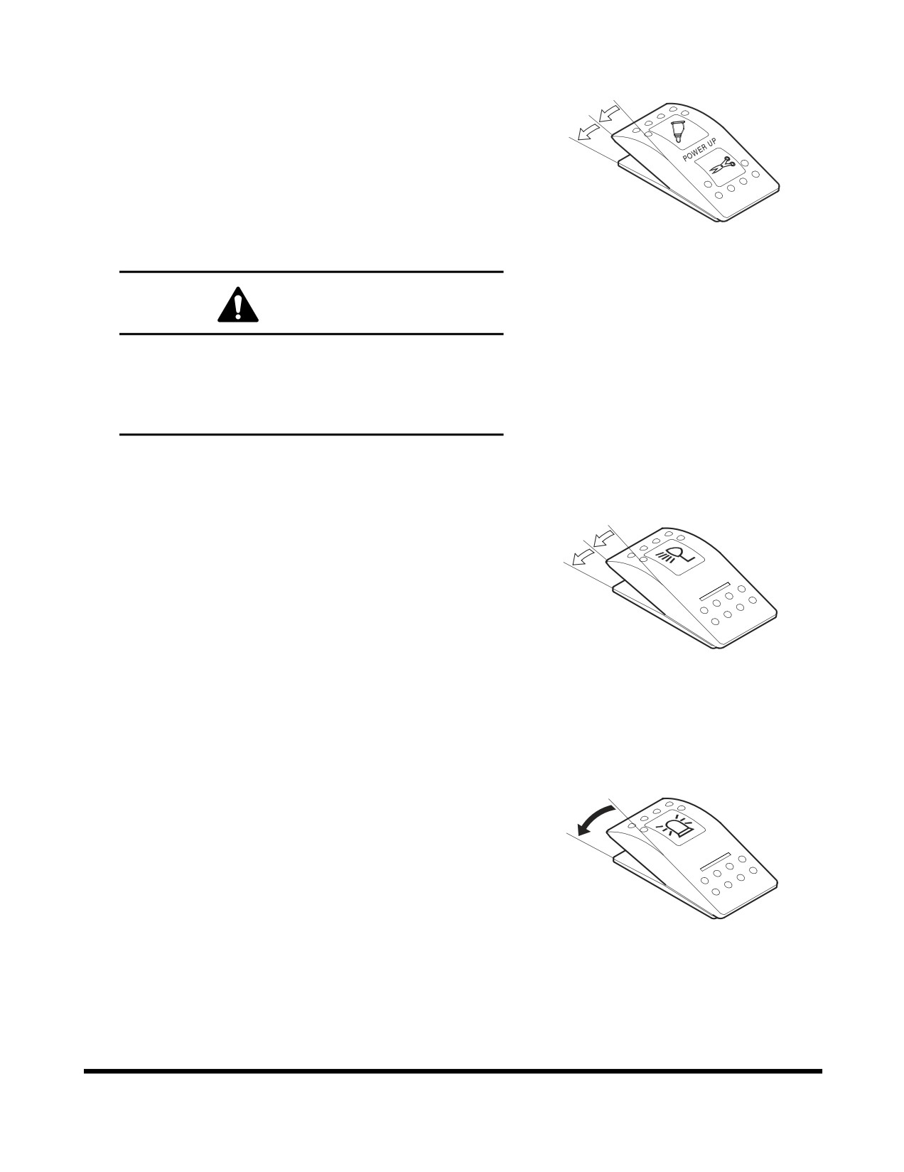
9. Breaker / Boost / Shear Selector
Switch
I
O
This switch is used to either select the breaker, power
II
boost, or shear.
O. In this position, a hydraulic pressure rise will be
activated when pressing the button on the right-hand
work lever (joystick).
I.
In this position, shear is activated.
FG000025
II.
In this position, breaker is activated.
Figure 16
WARNING!
Before using any attachment in a work application, be
sure to check its functional control. Make sure that the
desired movement or action is being activated by the
control. e.g. opening/closing, CW/CCW, crowd/dump,
etc.
10. Cabin Work Light Switch (Optional)
This switch is used to control the cabin work lights, if unit is
O
equipped with them.
I
II
O. In this position, all cabin work lights are turned "OFF."
I.
In this position, the front cabin work lights on the front
top of cabin will turn "ON."
II.
In this position, the front cabin work lights on the front
top of cabin and rear cabin work lights on rear top of
cabin will turn "ON."
FG000026
Figure 17
11. Warning Light Switch (Optional)
If unit is equipped with a warning light, push this switch to
O
activate it.
I
O. In this position, the warning light is turned "OFF."
I.
In this position, the warning light turns "ON" and will
start flashing.
FG000027
Figure 18
Operating Controls
OP000597
2-15
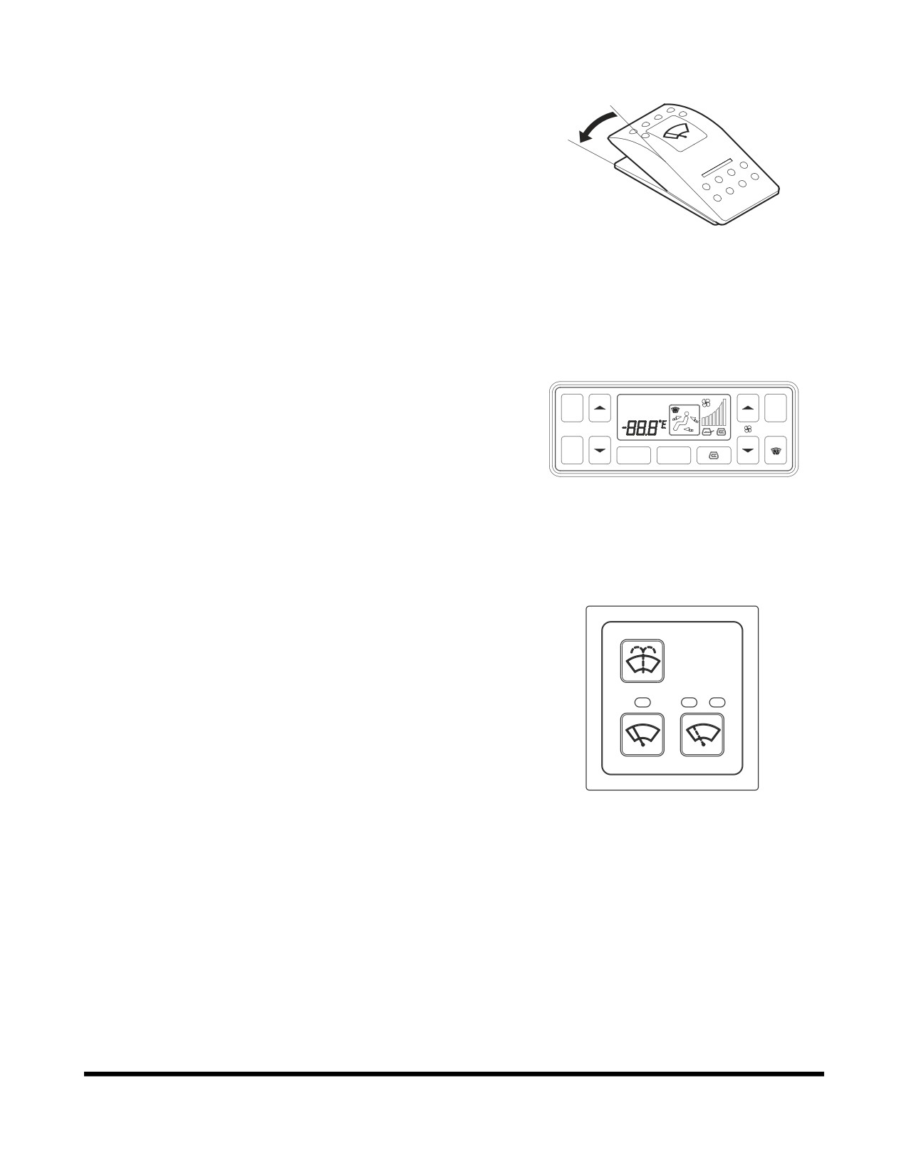
12. Lower Wiper Switch (Optional)
This switch is used to control the lower front window wiper.
O
O. In this position, lower windshield wiper is "OFF."
I
I.
In this position, lower windshield wiper runs at a
constant speed.
NOTE: Operating wiper without washer fluid or when
there is sand or dirt present will damage the
window and wiper.
FG000028
Figure 19
13. Heater and Air Conditioner Control
Panel
This panel is used to control air conditioner and heater in
A/C
OUTSIDE
operator's compartment. Refer to
“Heater and Air
AUTO
AUTO
MAX
A/C
Conditioner Control Panel” on page 2-51 for more details.
TEMP
OFF
SEL
MODE
FG000029
Figure 20
14. Wiper Switch Panel
This panel is only for operation of the upper windshield
wiper. When the wiper stops running, it moves to right side
of the cabin, resting in its support.
NOTE: When the front window is lifted, the wiper motor
will not operate.
FG000308
Figure 21
Operating Controls
OP000597
2-16
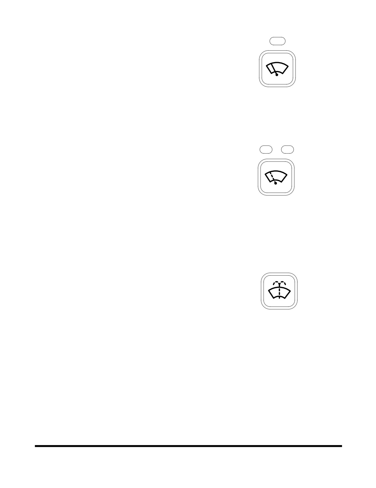
Constant Speed Button
Pressing the button turns "ON" the windshield wiper. An
indicator light above the button will turn "ON" indicating
that the wiper is "ON." The wiper will run at a constant
speed.
Pressing the button again, turns "OFF" the windshield
wiper.
FG000241
Figure 22
Intermittent Speed Button
Pressing button once (first time):
Windshield wiper runs approximately on a three
second intermittent cycle. The left side indicator light
will turn "ON."
Pressing button again (second time):
Windshield wiper runs approximately on a six second
intermittent cycle. The right side indicator light will
turn "ON."
FG000242
Pressing button again (third time):
Figure 23
Turns "OFF" the windshield wiper. Both indicator
lights will be turned "OFF."
Windshield Washer Button
Pressing the washer button will spray windshield washer
fluid onto the windshield. Use only the proper windshield
washer fluid in the system.
NOTE: Do not operate the windshield washer without
any fluid. If operate without any fluid, the
washer motor may be damaged. Check level in
washer tank, and add fluid as required.
NOTE: Using soapy water or synthetic detergent
instead of window cleaning fluid, may damage
FG000243
the wiper blade or painted surfaces. Use
Figure 24
standard window cleaning fluid: SSK703
Operating Controls
OP000597
2-17
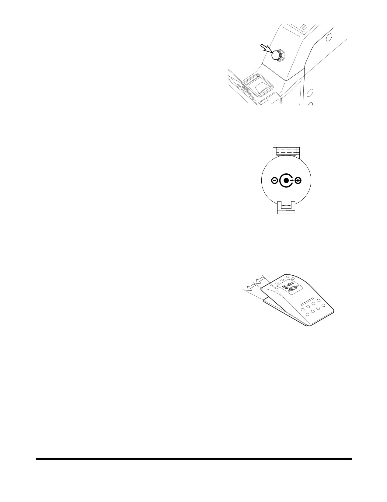
15. Cigarette Lighter
Push the lighter all the way into the socket and release
your hand. After pushing it in, it will be ejected when it is
heated. If it does not eject after a short time, pull it out and
have it serviced.
NOTE: This cigarette lighter is for
24V only. Never
connect a 12V electrical device to the lighter.
FG000030
Figure 25
16. Power Socket for 12 Volt
This is a power socket for only 12V DC devices.
This socket can be used for charging a cellular phone or
powering a small 12V DC electrical device.
Open the cap when using it.
12 V
NOTE: This socket is designed for small electrical
capacity devices. Do not use this socket for
large electrical capacity devices. Thus, damage
can be avoided.
HAAE1990
Figure 26
17. Travel/Swing Alarm Switch (Optional)
If unit is equipped with a travel/swing alarm buzzer, push
O
this switch to active it, whenever swinging or traveling.
I
O. In this position, the travel/swing alarm system is
II
turned "OFF."
I.
In this position, the travel alarm will only sound, when
the machine is moving.
II.
In this position, the travel/swing alarm will sound
while swinging and traveling, if equipped with a swing
FG000031
alarm device.
Figure 27
NOTE: If machine is only equipped with a travel
alarm device, the alarm will not sound
when swinging although the switch is in
the "II" position.
Operating Controls
OP000597
2-18
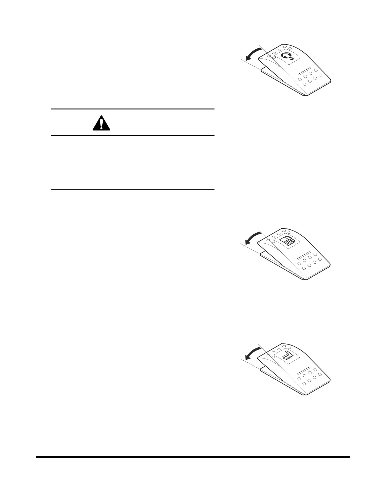
18. Overload Warning Switch (Optional)
If unit is equipped with an overload warning device, push
O
this switch to activate it.
O. In this position, the overload warning device is turned
I
"OFF."
I.
In this position, when a load is lifted that reaches the
machine safe lifting limit, a warning light on the
instrument panel will turn "ON" and a warning buzzer
will sound.
FG000032
Figure 28
WARNING!
To prevent injury, do not exceed the rated load
capacity of the machine. If the machine is not on level
ground, load capacities will vary. There may be local
government regulations about the use of excavators
for lifting objects.
Please observe these regulations.
19. Fuel Heater Switch (Optional)
This switch is used to activate the fuel heater system.
O
When the switch is activated, the fuel is warmed,
depending upon the temperature of the fuel.
I
NOTE: If the fuel temperature is above 5°C (41°F),
heating system is not activated.
O. In this position, the fuel heater system is turned
"OFF."
I.
In this position, the fuel heater system is turned "ON."
FG000033
Figure 29
NOTE: The starter switch must be "ON."
20. Seat Warmer Switch (Optional)
If the seat is equipped with the optional seat warmer, push
O
this switch to activate it.
I
When the seat is warmed, the warmer is automatically
turned "OFF."
O. In this position, the seat warmer is turned "OFF."
I.
In this position, the seat warmer is turned "ON."
NOTE: The starter switch must be "ON" with the engine
FG000034
running, for the heater to operate.
Figure 30
Operating Controls
OP000597
2-19
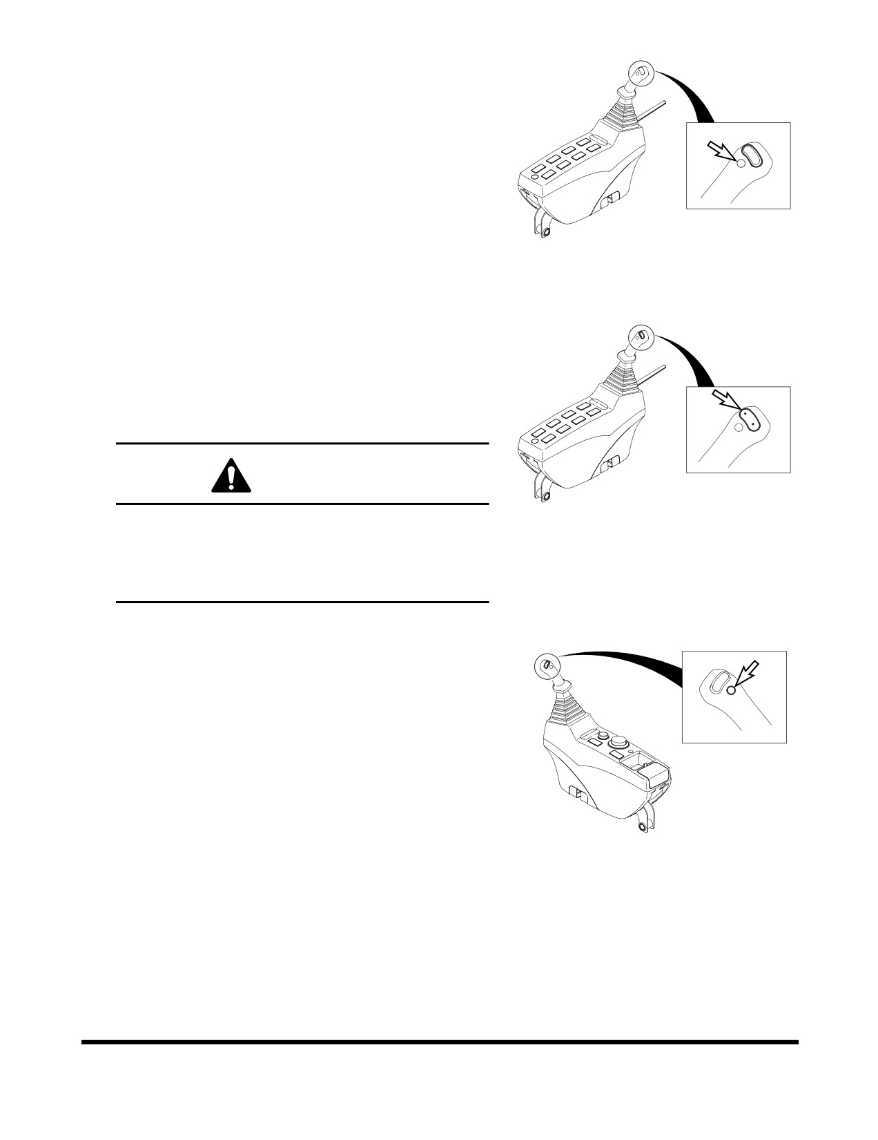
21. Horn Button (Left-hand Work Lever)
Press the lower button on the top of the left-hand work
lever (joystick) to sound horn.
NOTE: The starter switch must be "ON."
FG002084
Figure 31
22. Rotating Buttons
For a machine equipped with an attachment that rotates,
press the upper two buttons on the top of the left-hand
work lever (joystick) to rotate the attachment clockwise or
counterclockwise. Left button is for counterclockwise and
the right one is for clockwise.
WARNING!
FG000382
Figure 32
Before using any attachment in a work application, be
sure to check its functional control. Make sure that the
desired movement or action is being activated by the
control. e.g. opening/closing, CW/CCW, crowd/dump,
etc.
23. Booster Button (Right-hand Work
Lever)
Press the lower button on the top of the right-hand work
lever (joystick) to boost the hydraulic pressure. Refer to the
“Boost Mode” on page 3-22.
NOTE: This button works with the breaker/boost/shear
selector switch. See “9. Breaker / Boost / Shear
Selector Switch” on page 2-15.
FG000036
Figure 33
Operating Controls
OP000597
2-20
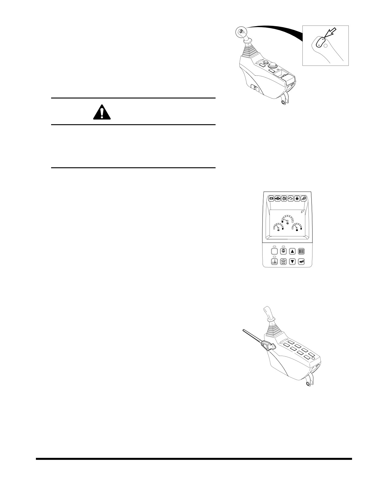
24. Shear Buttons
For a machine equipped with shear, press the two upper
buttons on the top of the right-hand work lever (joystick) to
open or close the shear. Left button is for closing (crowd),
right button is for opening (Dump).
NOTE: These buttons work with the breaker/boost/
shear selector switch. See “9. Breaker / Boost /
Shear Selector Switch” on page 2-15.
FG000383
Figure 34
WARNING!
Before using any attachment in a work application, be
sure to check its functional control. Make sure that the
desired movement or action is being activated by the
control. e.g. opening/closing, CW/CCW, crowd/dump,
etc.
25. Instrument Panel
CHECK
See “Instrument Panel” on page 2-24.
02/05 [MO] 11:30
E
F
C
H
C
H
E/G SPEED
1700
RPM
POWER
AUTO
1
2
3
4
ESC
5
6
7
8
FG000037
Figure 35
26. Safety Lever
See “Safety Lever” on page 3-13.
FG000038
Figure 36
Operating Controls
OP000597
2-21

27. Photo Sensor
The photo sensor detects the radiant energy of the sun.
In auto mode the air conditioner will automatically adjust
the air temperature based on to the detected radiant
energy.
FG000399
Figure 37
Operating Controls
OP000597
2-22
Operating Controls
OP000597
2-23
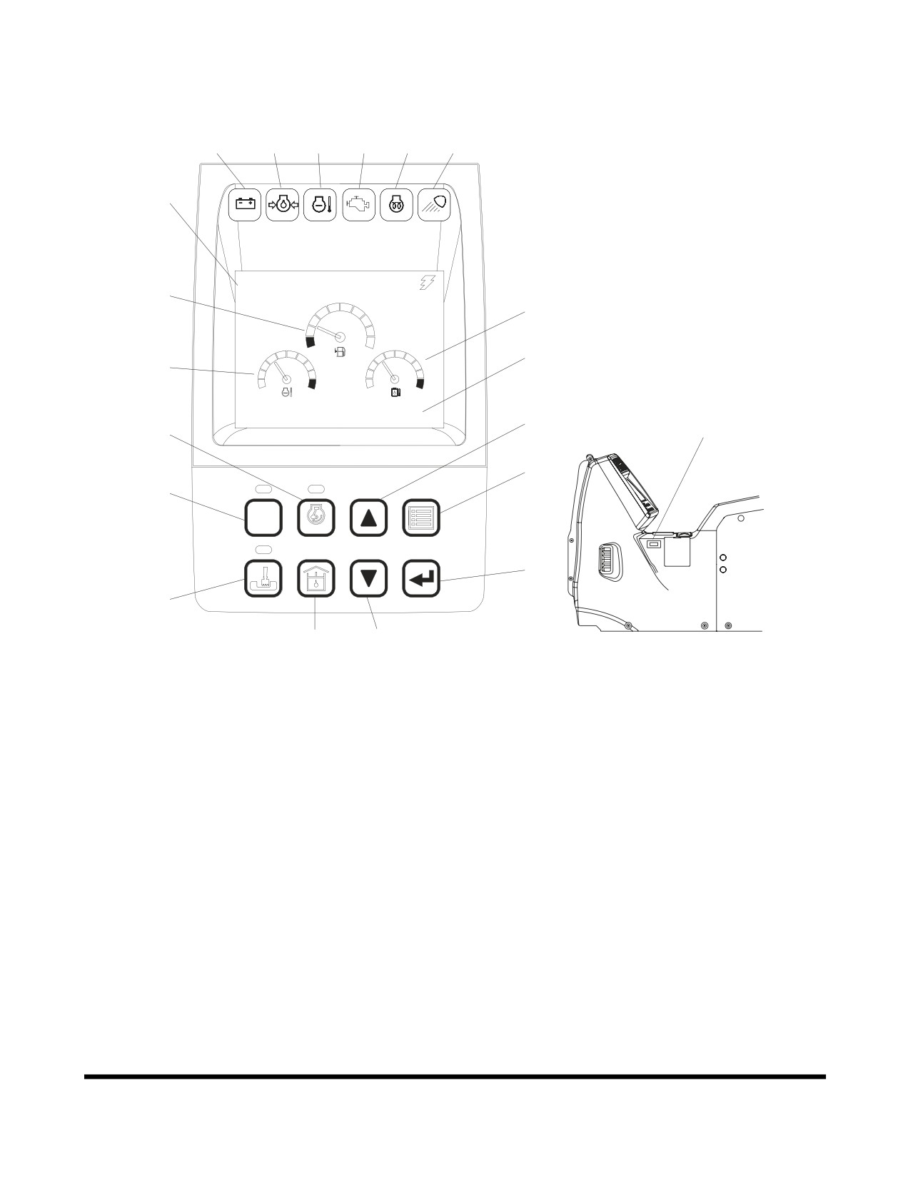
INSTRUMENT PANEL
7
8
9
10
11
12
5
CHECK
02/05 [MO] 11:30
1
3
E
F
4
2
C
H
C
H
E/G SPEED
1700
RPM
17
6
15
19
13
POWER
AUTO
1
2
3
4
ESC
20
14
5
6
7
8
16
18
FG000039
Figure 38
Operating Controls
OP000597
2-24
Reference
Reference
Description
Description
Number
Number
1
Fuel Gauge
12
Work Light Indicator Light
2
Engine Coolant Temperature
13
Power Mode Selector Button
Gauge
(See page 2-36)
3
Hydraulic Oil Temperature
14
Trenching Mode Selector Button
Gauge
(See page 2-37)
4
Multifunction Gauge And Graphic
15
Auto Idle Selector Button
Information Area (See page
(See page 2-37)
2-31)
16
Flow Control Button
5
Digital Clock
(See page 2-37)
6
Hour Meter
17
Up Arrow Button
(See page 2-38)
7
Charge Warning Light
18
Down Arrow Button
8
Engine Oil Pressure Warning
(See page 2-39)
Light
19
Display Selector Button
9
Engine Coolant Temperature
(See page 2-39)
Warning Light
20
Selection Button
10
Engine Check Warning Light
(See page 2-39)
11
Preheat Indicator Light
Functional check
When the engine starter switch is turned to the "I" (ON) position,
all gauge bands, switch/button indicator lights and indicator/
warning lights will turn "ON" and the alarm buzzer will sound
about two seconds.
During this functional check, a LOGO will appear on the multi
function gauge in the graphic information area (3 and 4, Figure
38).
Password Activated
If a password has already been set and the system has been
"LOCKED," the password display will appear on the screen once
the functional check has been completed. Enter the password
into the text area and then engage the starter.
NOTE: Refer to
“Set Password
(Lock and Unlock)” on
page 2-45, for further details.
CAUTION!
If the password does not match the stored password, the
engine will not start.
Operating Controls
OP000597
2-25
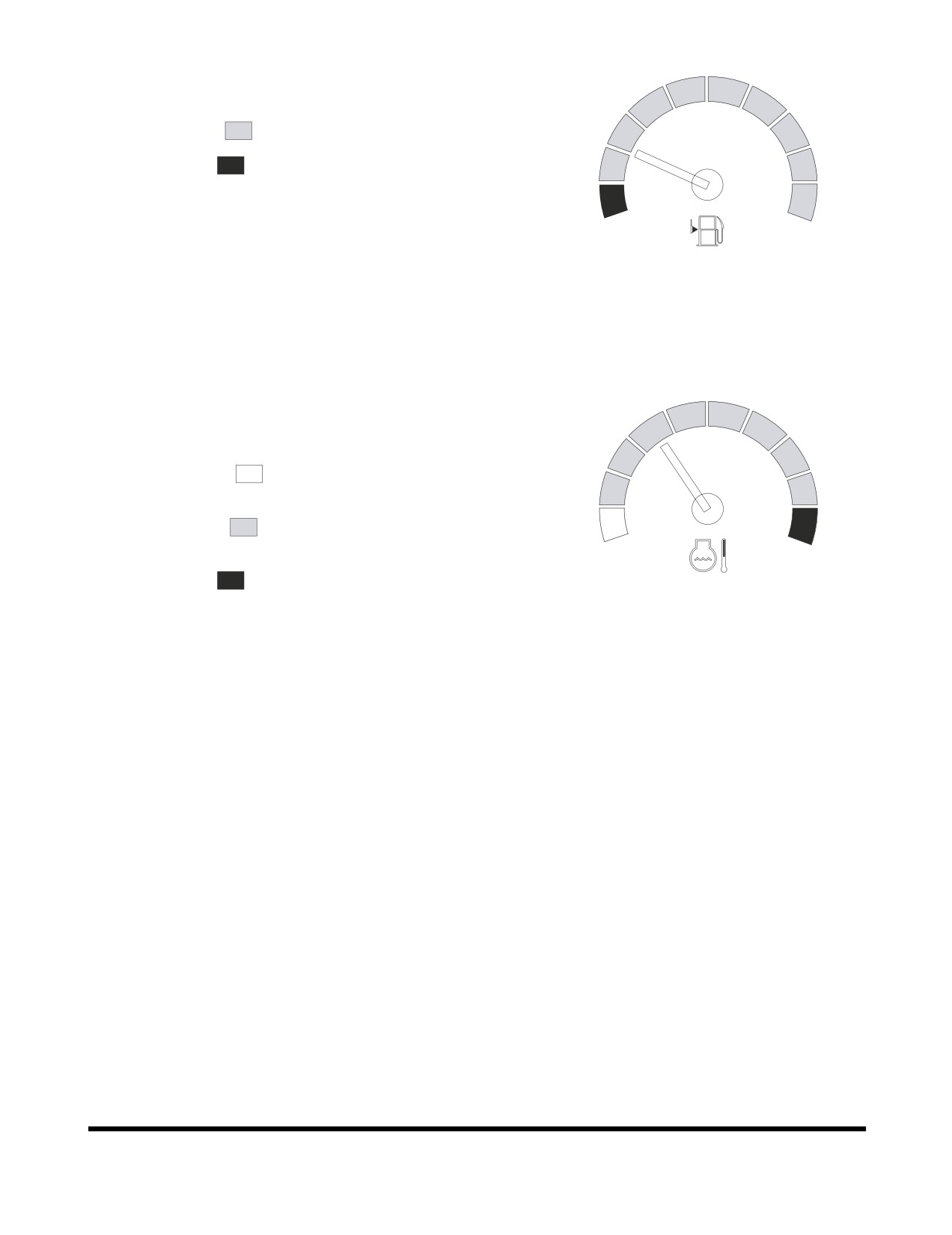
1. Fuel Gauge
Shows remaining fuel quantity in tank.
BLUE ZONE (
) - Indicates a normal fuel quantity.
RED ZONE (
) - Indicates that the fuel level is low.
If the gauge pointer moves into the red zone, the fuel level
symbol will turn "ON," and be display in the screen. Stop
E
F
operation and immediately and add fuel.
FG000040
NOTE: See “Abnormal State Warning Symbols” on
page 2-33, for location of this warning symbol
Figure 39
and others.
Check the fuel level on firm, level ground.
2.
Engine Coolant Temperature Gauge
The colored bands indicate the temperature of the engine
coolant.
WHITE ZONE (
) - Indicates temperature is lower than
the normal operating temperature.
BLUE ZONE (
)
- Indicates temperature is within the
C
H
normal operating range.
RED ZONE (
) - Indicates temperature is too high.
FG000041
Figure 40
During operation, the pointer must be in the blue zone.
If the gauge pointer moves into the red zone, the engine
coolant temperature warning light will turn "ON," a warning
buzzer will sound, and the engine speed will be
automatically reduced. Allow the engine to run at low idle
speed until the temperature gauge registers in the blue
zone again. When the blue zone is reached, allow the
engine to idle for an additional three - five minutes before
shutting down the engine. If not allowed to idle, heat surge
may develop which will damage the engine. Allowing the
engine to idle will dissipate heat. Check the coolant level,
look for a loose fan belt, inspect for debris around radiator,
and so on.
When the temperature reaches the normal range, the
engine speed will automatically recover.
Operating Controls
OP000597
2-26
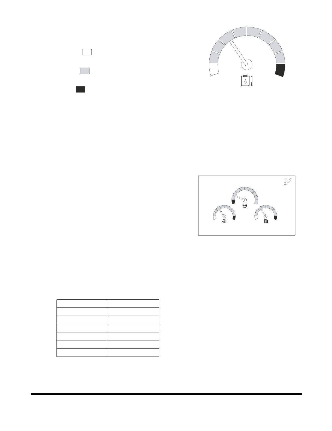
3. Hydraulic Oil Temperature Gauge
The colored bands indicate the temperature of the
hydraulic oil
WHITE ZONE (
) - Indicates temperature is lower than
the normal operating temperature.
BLUE ZONE (
)
- Indicates temperature is within the
C
H
normal operating range.
RED ZONE (
) - Indicates temperature is too high.
FG000042
Figure 41
During operation, the pointer must be in the blue zone.
If the gauge pointer moves into the red zone, the hydraulic
oil temperature symbol will turn "ON," and be display in the
screen. Allow the engine to run at low idle speed until the
temperature gauge registers in the blue zone again.
NOTE: See “Abnormal State Warning Symbols” on
page 2-33, for location of this warning symbol
and others.
4. Multifunction Gauge and Graphic
02/05 [MO] 11:30
Information Area
See “Multifunction Gauge and Graphic Information” on
page 2-31. This section will have a more in-depth
E
F
explanation of the display area.
C
H
C
H
E/G SPEED 1700 RPM
FG000043
Figure 42
5. Digital Clock
A digital clock, shows the current time. The displayed
contents are as follows.
Display
Description
MM/DD [W] HH:mm
MM
Month
DD
Date
W
Day
HH
Hour
FG000044
mm
Minute
Figure 43
A (P)
AM (PM)
Refer to the “Setting Main Menu” on page 2-38 for time
setting.
Operating Controls
OP000597
2-27
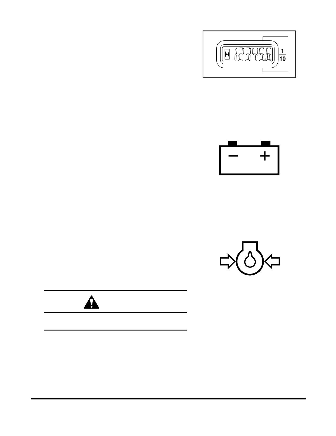
6. Hour Meter
The hour meter is used to indicate the total number of
running hours on the engine. The meter will flash every
four seconds when the engine is running to indicate that it
is functioning properly.
HAOA601L
Figure 44
7. Charge Warning Light
This indicator light will turn "ON" when the engine starter
switch is turned "ON," and should go "OFF" after the
engine starts. If it does not turn "OFF," shut the engine
down immediately and determine the cause of the
problem.
HAOA610L
Figure 45
8. Engine Oil Pressure Warning Light
This indicator light will turn "ON" when the engine starter
switch is turned "ON," and should go "OFF" after the
engine starts. For example, if the engine oil pressure
becomes too low, the light will turn "ON" and a warning
buzzer will sound. If this happens, shut the engine down
immediately and determine the cause of the problem. If
you continue to work when this light is "ON," it will result in
serious engine damage.
HAOA620L
Figure 46
CAUTION!
If you continue to work when this light is "ON," it will
result in serious engine damage.
Operating Controls
OP000597
2-28
9.
Engine Coolant Temperature Warning
Light
If engine coolant overheats, this light will turn "ON," an
alarm will sound, and the engine speed will be
automatically reduced, until coolant temperature drops. Do
not turn engine "OFF" because this will cause coolant
temperature to rise and may cause engine to siege due to
heat surge.
NOTE: Check the engine coolant temperature gauge. If
HAOD350L
the gauge pointer moves into the red zone, the
Figure 47
engine coolant temperature warning light will
turn "ON," a warning buzzer will sound, and the
engine speed will be automatically reduced.
Allow the engine to run at low idle speed until
the temperature gauge registers in the blue
zone again. When the blue zone is reached,
allow the engine to idle for an additional three -
five minutes before shutting down the engine. If
not allowed to idle, heat surge may develop
which will damage the engine. Allowing the
engine to idle will dissipate heat. Check the
coolant level, look for a loose fan belt, inspect
for debris around radiator, and so on.
When the temperature reaches the normal
range, the engine speed will automatically
recover.
10. Engine Check Warning Light
This indicator light will turn "ON," when the engine needs to
be check.
NOTE: If this light turns "ON" stop the machine and
repair the cause of the fault.
CHECK
FG000045
Figure 48
Operating Controls
OP000597
2-29
11. Preheating Indicator Light
In cold weather this light indicates that the engine preheat
function is operating.
When this indicator light turns "OFF," it means that the
engine preheat cycle has been completed.
HAAE2000
Figure 49
12. Work Light Indicator Light
The indicator light indicates that the work lights are turned
"ON."
HB4O2003
Figure 50
Operating Controls
OP000597
2-30
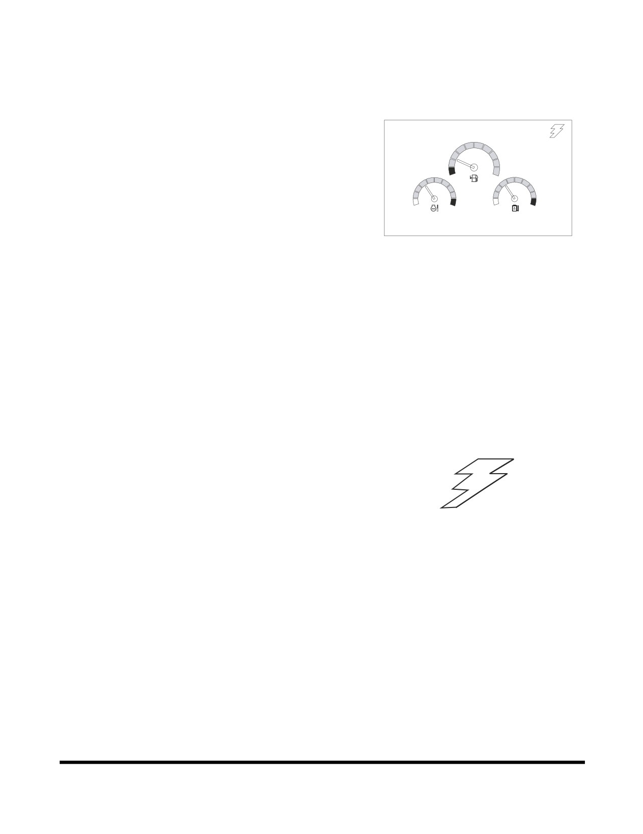
MULTIFUNCTION GAUGE AND
GRAPHIC INFORMATION
When the engine starter switch is turned to the "I" (ON) position,
a LOGO will appear on the display screen for about two
02/05 [MO] 11:30
seconds.
When the LOGO disappears, the multifunction gauge and
graphic information screen will appear.
E
F
The engine rpm is normally displayed at the bottom of the
screen when the starter switch is first turned "ON." Each time the
C
H
C
H
display selector button (19, Figure 38) is pressed, the digital
readout changes in the following sequence; Engine speed
E/G SPEED 1700 RPM
(RPM) -> Battery voltage (VOLT) -> Front pump pressure (BAR)
FG000043
-> Rear pump pressure (BAR).
Figure 51
NOTE: See Figure 54 thru Figure 57.
A digital clock is located at the top of the display.
By using a combination of the mode selector buttons,
information for filters and oils can also be displayed.
The display can also be set for the desired language.
Refer to the “Setting Main Menu” on page 2-38 for the language
selection and information display sequences.
Communication Indicator
Indicates the condition of communication between main
controller and instrument panel.
1.
Normal Condition:
The symbol will sequentially move like lightening.
NOTE: See Figure 54 thru Figure 57.
2.
Abnormal Condition:
If the symbol is not displayed, it means there is a
FG000047
communication error.
Figure 52
NOTE: See Figure 53.
Operating Controls
OP000597
2-31
Communication Error Warning
If a communication error is generated between e-EPOS
controller and instrument panel, this symbol will be displayed.
When this symbol is displayed, contact a DOOSAN distributor or
sales agency.
NOTE: If a communication error occurs during operation, the
last mode setting is stored. e.g. power mode, work
mode and auto idle are stored during failure.
NOTE: When starter switch is turned to the "I" (ON) position
FG000048
during a state of communication error failure, the
Figure 53
e-EPOS controller will default to the following modes.
Power mode: Standard mode
Working mode: Digging mode
Auto idle: "ON" (Selection state)
Engine Speed
The engine speed is numerically displayed.
E/G SPEED 1700 RPM
FG000049
Figure 54
Battery Voltage
The battery voltage is numerically displayed. With the engine
running, the reading should be between 26V - 30V.
When the starter is engaged or the preheat system is being
used, the voltage can temporarily drop below 24V, but this is a
BATTERY 28.0 VOLT
normal condition.
FG000050
Figure 55
Operating Controls
OP000597
2-32
Front Hydraulic Pump Pressure
The front pump pressure is numerically displayed.
NOTE: This pump is closest to engine flywheel housing
or is the upper one of hydraulic pump.
FRONT PUMP 320 BAR
It displays the reading in BARs.
FG000051
Figure 56
Rear Hydraulic Pump Pressure
The rear pump pressure is numerically displayed.
NOTE: This pump is the farthest from engine flywheel
housing or is the lower one of hydraulic pump.
REAR PUMP 313 BAR
It displays the reading in BARs.
FG000052
Figure 57
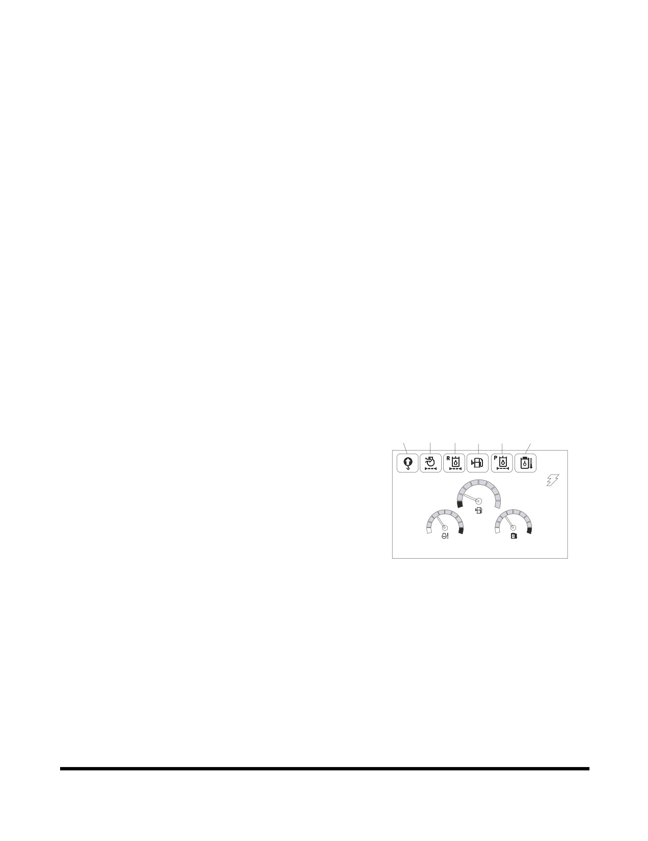
Abnormal State Warning Symbols
6
5
4
3
2
1
1.
Hydraulic Oil Overheating Warning
2.
Pilot Filter Clogged Warning
3.
Fuel Shortage Warning
E
F
4.
Return Filter Clogged Warning
5.
Air Cleaner Clogged Warning
C
H
C
H
6.
Overload Warning (Optional)
E/G SPEED 1700 RPM
FG001088
Figure 58
Operating Controls
OP000597
2-33