Doosan DX140LC. Operation and Maintenance Manual (2007) - page 3
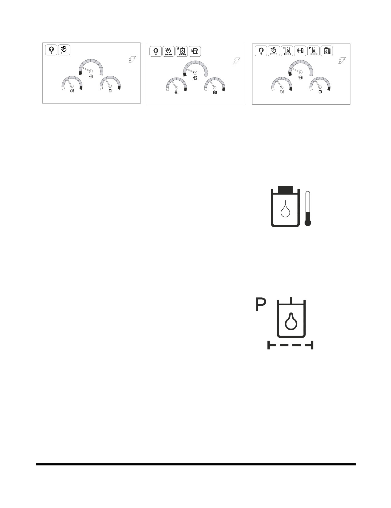
Examples of Warning Display
02/05 [MO] 11:30
02/05 11:30
E
F
E
F
E
F
C
H
C
H
C
H
C
H
C
H
C
H
E/G SPEED 1700 RPM
E/G SPEED 1700 RPM
E/G SPEED 1700 RPM
FG000059
FG000060
FG000061
<2 kinds of warning display>
<4 kinds of warning display>
<6 kinds of warning display>
Figure 59
1.
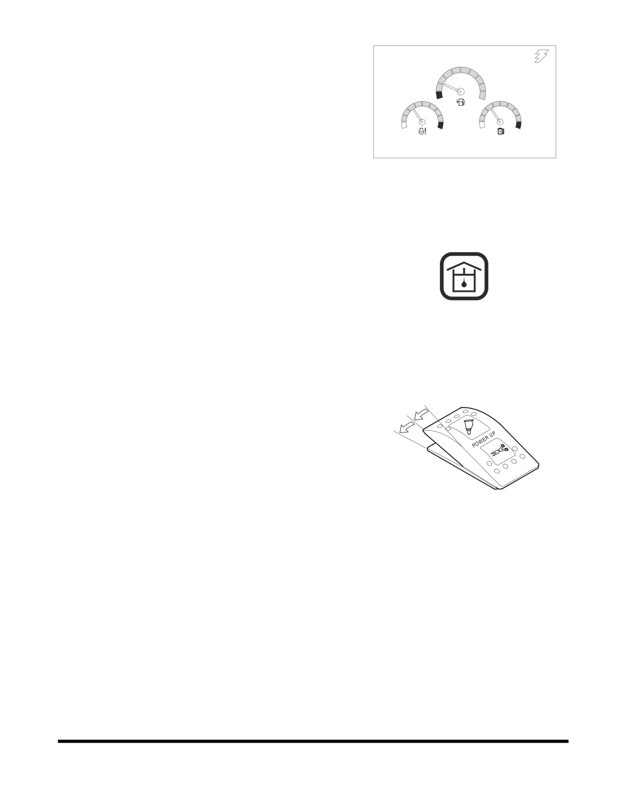
Hydraulic Oil Overheat Warning
If the hydraulic oil temperature is too high, this symbol
appears on the screen.
FG000056
Figure 60
2.
Pilot Filter Clogged Warning
This symbol indicates when the pilot filter clogged.
If this symbol is displayed, immediately stop operation and
replace the pilot filter.
After the pilot filter has been serviced, restart machine
operation to remove the warning symbol.
FG000055
Figure 61
Operating Controls
OP000597
2-34
3.
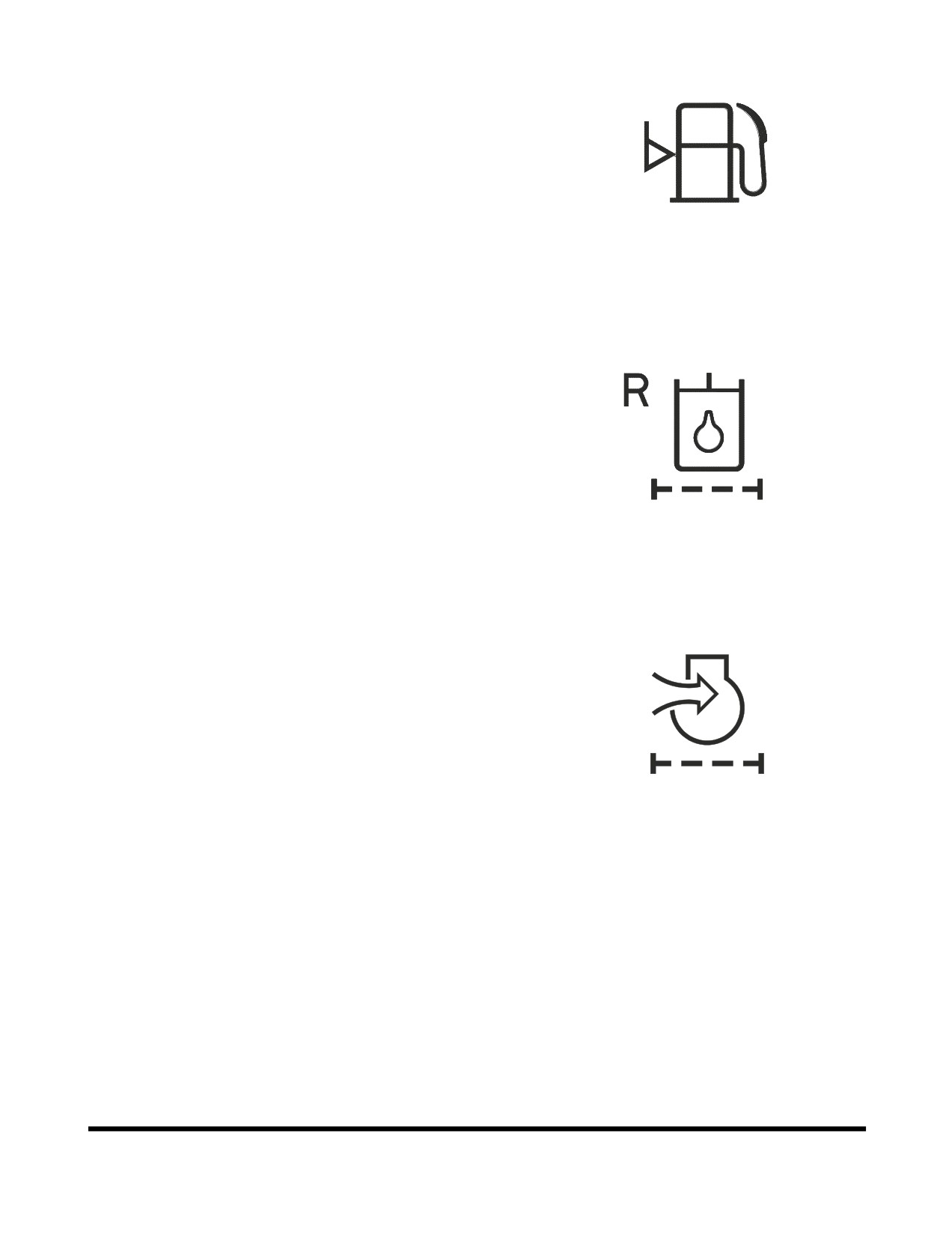
Fuel Shortage Warning
If the fuel quantity is too low, this symbol appears on the
screen.
If this light turns "ON," add fuel as soon as possible.
FG000057
Figure 62
4.
Return Filter Clogged Warning
This symbol indicates when the hydraulic return filter is
clogged.
If this symbol is displayed, immediately stop operation and
replace the return filter.
After the return filter has been serviced, restart machine
operation to remove the warning symbol.
FG000054
Figure 63
5.
Air Cleaner Clogged Warning
This symbol indicates when the air cleaner is clogged.
If this symbol is displayed, immediately stop operation and
replace or clean the air filter.
After the air filter has been serviced, restart machine
operation to remove the warning symbol.
FG000053
Figure 64
Operating Controls
OP000597
2-35
6.
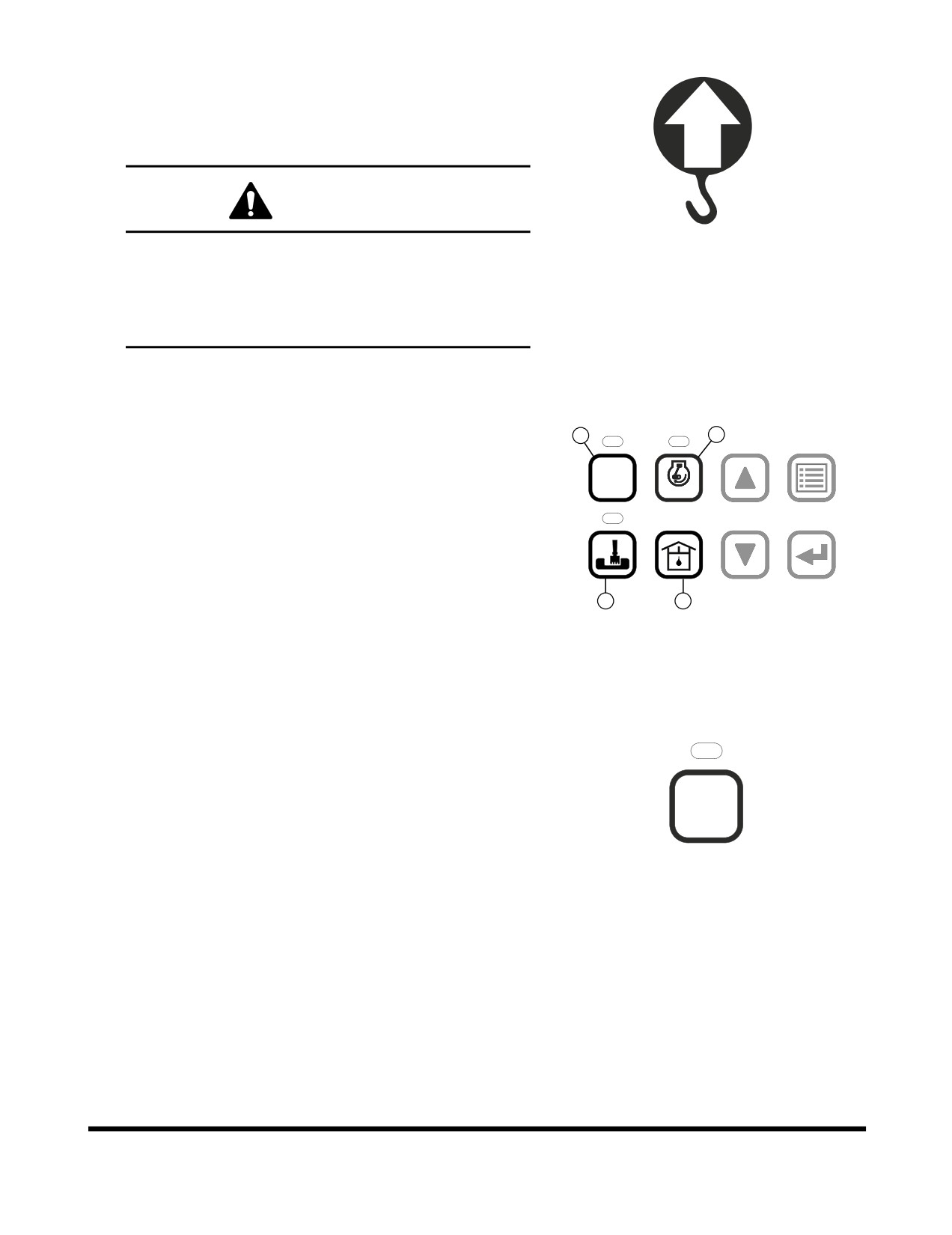
Overload Warning (Optional)
If the overload warning switch is turned "ON," and this
symbol appears on the screen and the warning buzzer
sounds, that indicates that overloaded condition is
occurring. Immediately reduce the load.
WARNING!
If this warning appears on the screen and a warning
FG000253
buzzer sound, reduce the load immediately.
Figure 65
If you continue to work, the machine can be turned
over or damage to hydraulic components and
structural parts could occur.
MODE SELECTOR BUTTONS
1
3
1.
Power Mode Selector Button
POWER
2.
Trenching Mode Selector Button
AUTO
1
2
3
4
ESC
3.
Auto Idle Selector Button
4.
Flow Control Button
5
6
7
8
2
4
FG001338
Figure 66
1. Power Mode Selector Button
This power mode is suitable for heavy-duty work that
requires a high operating speed. Push this button to turn
power mode "ON" or "OFF."
When the power mode button is pushed to the "ON"
POWER
position, an indicator light above it turns "ON."
1
When the power mode button is pushed again, it is turned
"OFF" and the power mode is deactivated and returns to
the standard operating mode.
FG000063
When turning the engine starter switch to the "I" (ON)
Figure 67
position, the power mode is automatically defaulted to
"Standard Mode."
NOTE: For further details, see "“Mode Selection” on
page 3-20.
Operating Controls
OP000597
2-36
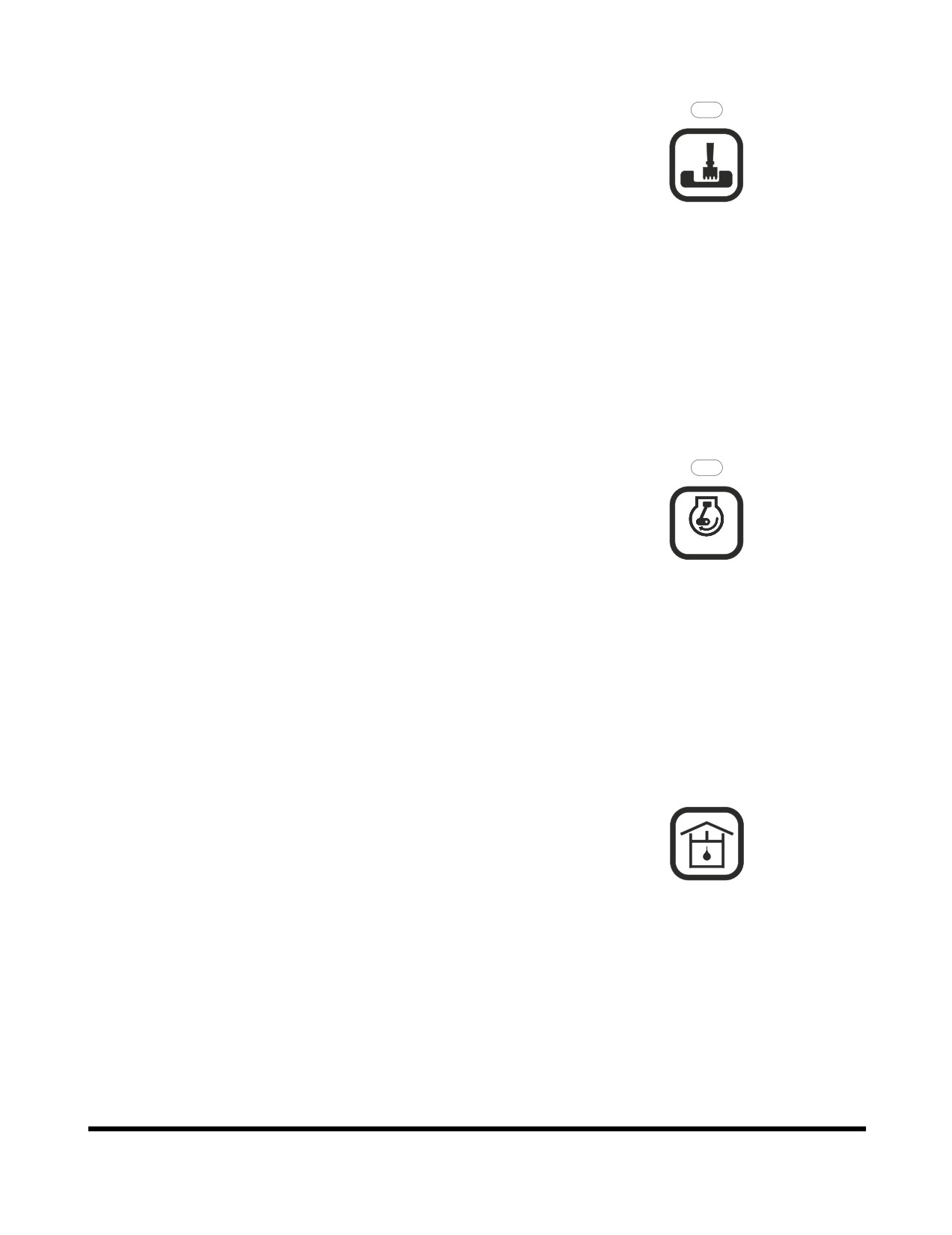
2. Trenching Mode Selector Button
This work mode is suitable for smooth trench or smooth
trench wall. Push this button to turn trenching mode "ON"
or "OFF."
When the trenching mode button is pushed to the "ON"
position, an indicator light above it turns "ON."
5
When the trenching mode button is pushed again, it is
turned "OFF" and the trenching mode is deactivated and
returns to the digging mode.
FG000064
When you turn the engine starter switch to the "I" (ON)
Figure 68
position, the work mode is automatically defaulted to
"Digging Mode."
NOTE: For further details, see "“Mode Selection” on
page 3-20.
3. Auto Idle Selector Button
When the auto idle system is activated, the engine will
automatically reduce speed to "IDLE" approximately four
seconds after all of the control levers are in the neutral
position. This system is designed to reduce fuel
consumption and noise.
AUTO
When the auto idle selector button is pushed to the "ON"
2
position, an indicator light above it turns "ON."
When the auto idle selector button is pushed again, it is
FG000065
turned "OFF" and the engine speed will return to the
Figure 69
setting of the engine speed dial and will remain at this
speed despite control lever position, until the engine speed
dial is moved.
4. Flow Control Button
When the button is pushed, you can control the hydraulic
oil flow rate.
The flow control button is used to set the flow rate of pump
to match the installed tool/attachment for optimal
performance, without damaging it.
6
NOTE: For further details, see "“Flow Control” on
page 2-47.
FG000066
Figure 70
Operating Controls
OP000597
2-37
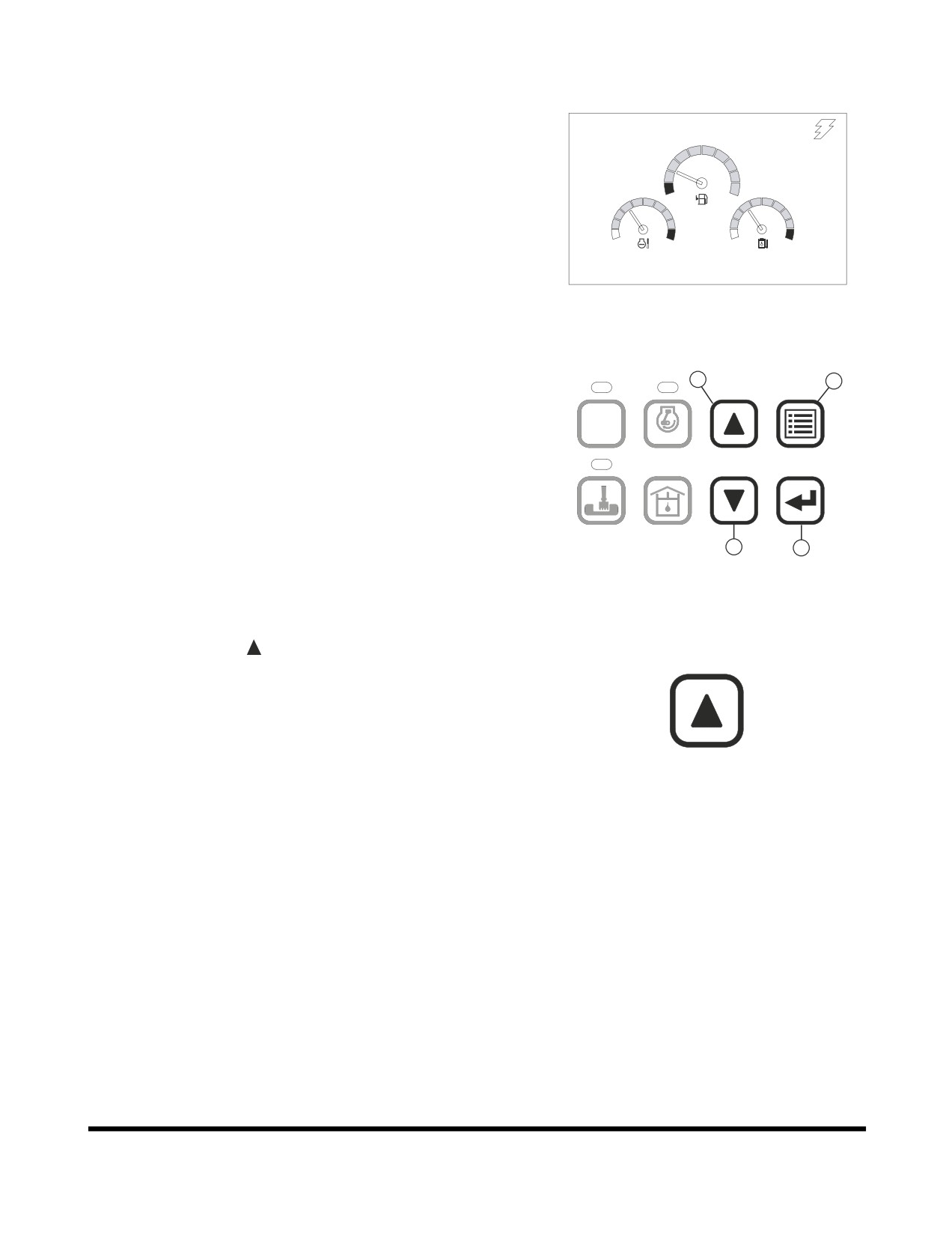
SETTING MAIN MENU
By using a combination of the selector buttons (Figure 72), you
can review and set the contents of the display screen. Items
02/05 [MO] 11:30
such as language, time and filter/oil information can be checked,
and if necessary, set with new information.
E
F
C
H
C
H
E/G SPEED 1700 RPM
FG000043
Figure 71
1
3
POWER
AUTO
1
2
3
4
ESC
5
6
7
8
2
4
FG001339
Figure 72
1. Up Arrow Button
Up arrow button (
), is used to move a menu item "Up" or
to the "Left."
3
FG000068
Figure 73
Operating Controls
OP000597
2-38
2. Down Arrow Button
Down arrow button (
), is used to move a menu item
"Down" or to the "Right."
7
FG000069
Figure 74
3. Display Selector Button (ESC - Escape)
Display selector button
(
), is used to change the
displayed information on the screen. Each time the display
selector button is pressed, the digital readout changes.
NOTE: When setting the main menu, this button is used
as the menu / exit button (ESC). To access the
4
menus the button must be pressed and held for
ESC
three seconds.
NOTE: When this button is used for menu / exit button,
FG000070
it is used to access to main menu or return to a
Figure 75
previous screen from each submenu.
4. Selection Button
Selection button (
), is used to set a menu or clear the
operating hour of filter/oil.
8
FG000071
Figure 76
Operating Controls
OP000597
2-39
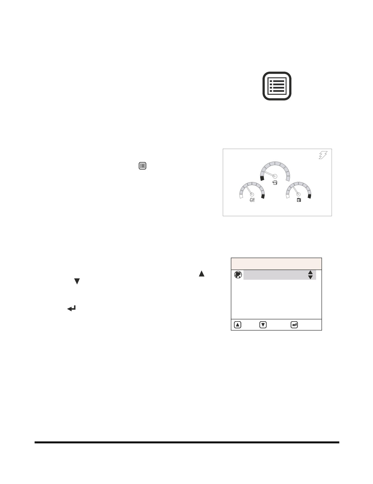
Display Selection and Escaping
Display Selection
When the display button (Figure 77) is pressed for more than
three seconds, the main menu screen (Figure 79) is displayed.
In the normal display screen, the engine speed (rpm), battery
voltage
(volt), front pump pressure
(bar), and rear pump
pressure (bar) can be displayed.
4
ESC
FG000070
Figure 77
ESC Button
02/05 [MO] 11:30
The screen will return from the main menu to the normal display
screen, by again pressing the "ESC" (
) button.
NOTE: If more than twenty seconds are spent in any menu,
E
F
without changing the screen, it will return to the
normal display screen.
C
H
C
H
E/G SPEED 1700 RPM
FG000043
Figure 78
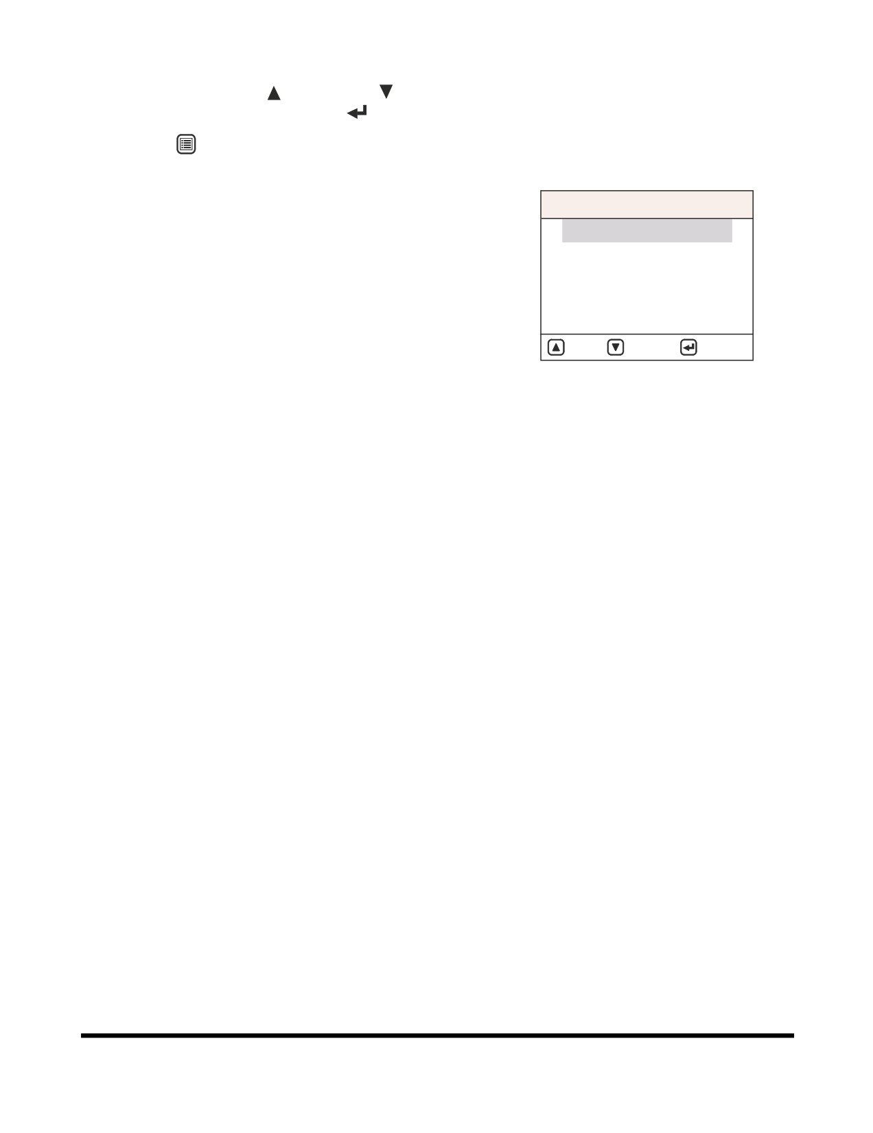
Main Menu
MAIN MENU
The menu selection can be changed by pressing the "UP" (
)
1. Language
or "DOWN" (
) buttons. The selected menu item will be
2. Set Clock
highlighted, and a cursor will appear by the menu item.
3. Filter / Oil Info
When the selected menu item is highlighted, press the
4. Adjust Display
"SELECT" (
) button to enter the next submenu.
5. Set Password
1.
“Language” on page 2-41.
: UP
: DOWN
: SELECT
2.
“Set Clock” on page 2-41.
FG000072
3.
“Filter / Oil Info” on page 2-42.
Figure 79
4.
“Adjust Display” on page 2-44
5.
“Set Password (Lock and Unlock)” on page 2-45
Operating Controls
OP000597
2-40
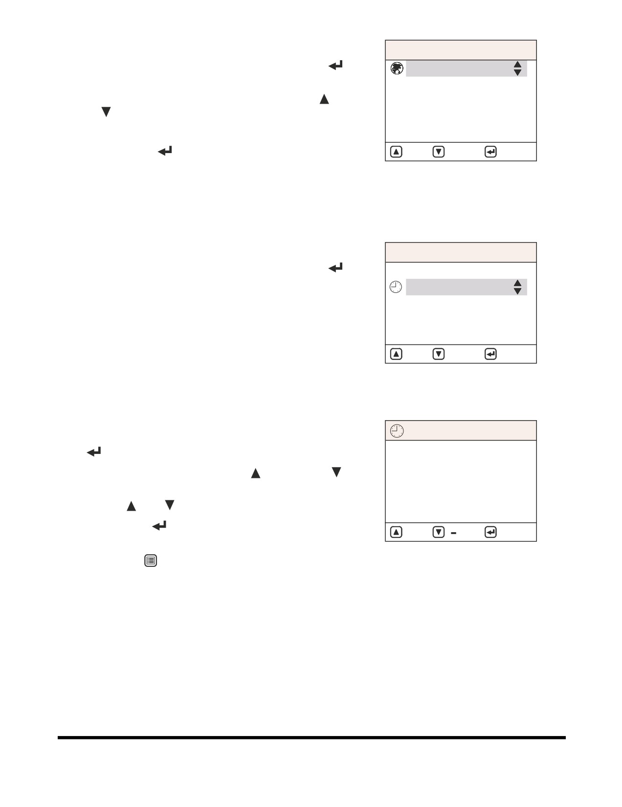
Language
MAIN MENU
When the cursor is on "Language," press the "SELECT" (
)
1. Language
button. The language submenu will appear.
2. Set Clock
The desired language can be selected by using the "UP" (
) or
3. Filter / Oil Info
"DOWN"(
) buttons.
4. Adjust Display
The display can be set for the desired language.
5. Set Password
Press the "SELECT" (
) button to set the selected language.
: UP
: DOWN
: SELECT
FG000072
NOTE: If more than twenty seconds are spent in the menu,
without changing the screen, it will return to the
Figure 80
normal display screen.
Set Clock
MAIN MENU
When the cursor is on "Set Clock," press the "SELECT" (
)
1. Language
button. The set clock submenu will appear.
2. Set Clock
NOTE: If more than twenty seconds are spent in the menu,
3. Filter / Oil Info
without changing the screen, it will return to the
4. Adjust Display
normal display screen.
5. Set Password
: UP
: DOWN
: SELECT
FG000075
Figure 81
Setting Method
SET CLOCK
1.
Move the cursor to desired number by using the "SELECT"
(
) button. When selected the number will flash.
2.
Set the time by using the "UP"
(
) or "DOWN"(
)
06:05
buttons.
2004 06/29
•
"+" (
), "-" (
): Increase or decrease number.
•
"MOVE" (
): Confirm and move the cursor to next
: +
:
: MOVE
number.
FG000076
•
"ESC" (
): Exit to the main menu.
Figure 82
Operating Controls
OP000597
2-41
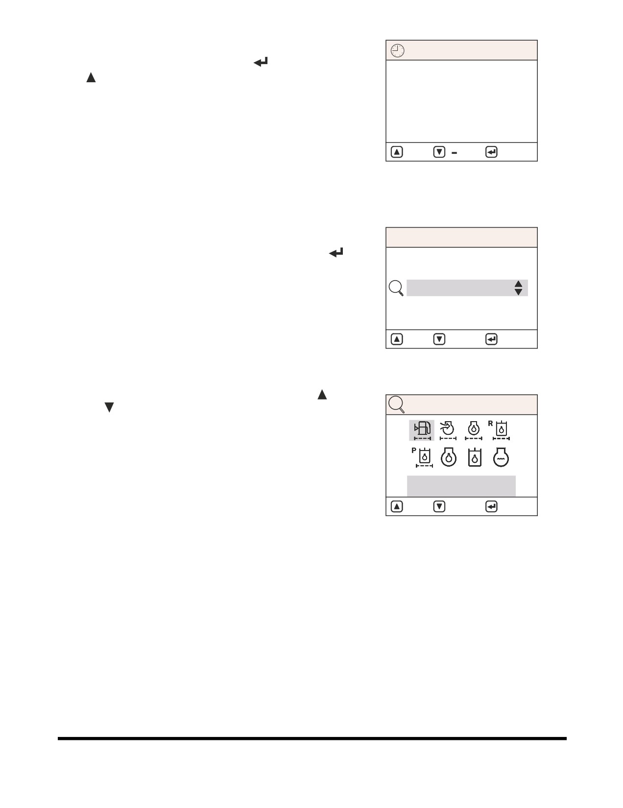
'00' Minute Setting
SET CLOCK
1.
Simultaneously press the "SELECT" (
) button and "UP"
(
) button.
06:05
2.
If the displayed time is 30 minutes or less, the clock will
display the preceding hour.
2004 06/29
3.
If the displayed time is more than 30 minutes, the clock will
display the succeeding hour.
: +
:
: MOVE
4.
When the preceding hour is more than 23, the day will be
increased.
FG000076
Figure 83
Filter / Oil Info
MAIN MENU
When the cursor is on "Filter/Oil Info," press the "SELECT" (
)
1. Language
button. The filter/oil information submenu will appear.
2. Set Clock
3. Filter / Oil Info
4. Adjust Display
5. Set Password
: UP
: DOWN
: SELECT
FG000077
Figure 84
Each symbol can be selected by pressing the "UP" (
) or
"DOWN" (
) buttons. At the bottom of the screen the operating
FILTER / OIL INFO
hour (Hrs) of each filter and/or oil is displayed.
1. Fuel Filter
Hrs : 0025
: UP
: DOWN
: RESET
FG000078
Figure 85
Operating Controls
OP000597
2-42
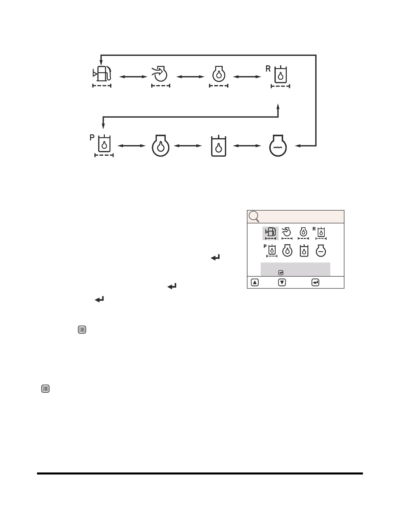
Menu Display Order and Icon Explanation
1. Fuel Filter
2. Air Cleaner
3. Engine Oil Filter
4. Hyd. Oil Filter
5. Pilot Filter
6. Engine Oil
7. Hydraulic Oil
8. Coolant Water
FG001358
Figure 86
Filter / Oils Operating Hour Reset
FILTER / OIL INFO
After changing a filter or oil, reset the operating hour to zero
(Hrs: 0000). The next replacement period can than be easily
checked. The operating hours are only accumulated while the
engine is running.
On the filter / oil information screen, press the "SELECT" (
)
button and then the reset screen will be displayed.
RESET?
YES :
NO : ESC
On the reset screen, the operating hour can be changed to zero
: UP
: DOWN
: RESET
hour (Hrs: 0000) by pressing the "SELECT" (
).
HAAE1960
If the "SELECT"
(
) button is pressed, the reset will be
Figure 87
completed. and the screen will be returned to the previous
menu.
If the "ESC" (
) button is pressed, the screen will be returned
to the previous menu without being reset.
NOTE: If more than twenty seconds are spent in the menu,
without changing the screen, it will return to the
normal display screen.
The screen is returned to the main menu by pressing the "ESC"
(
) button.
Operating Controls
OP000597
2-43
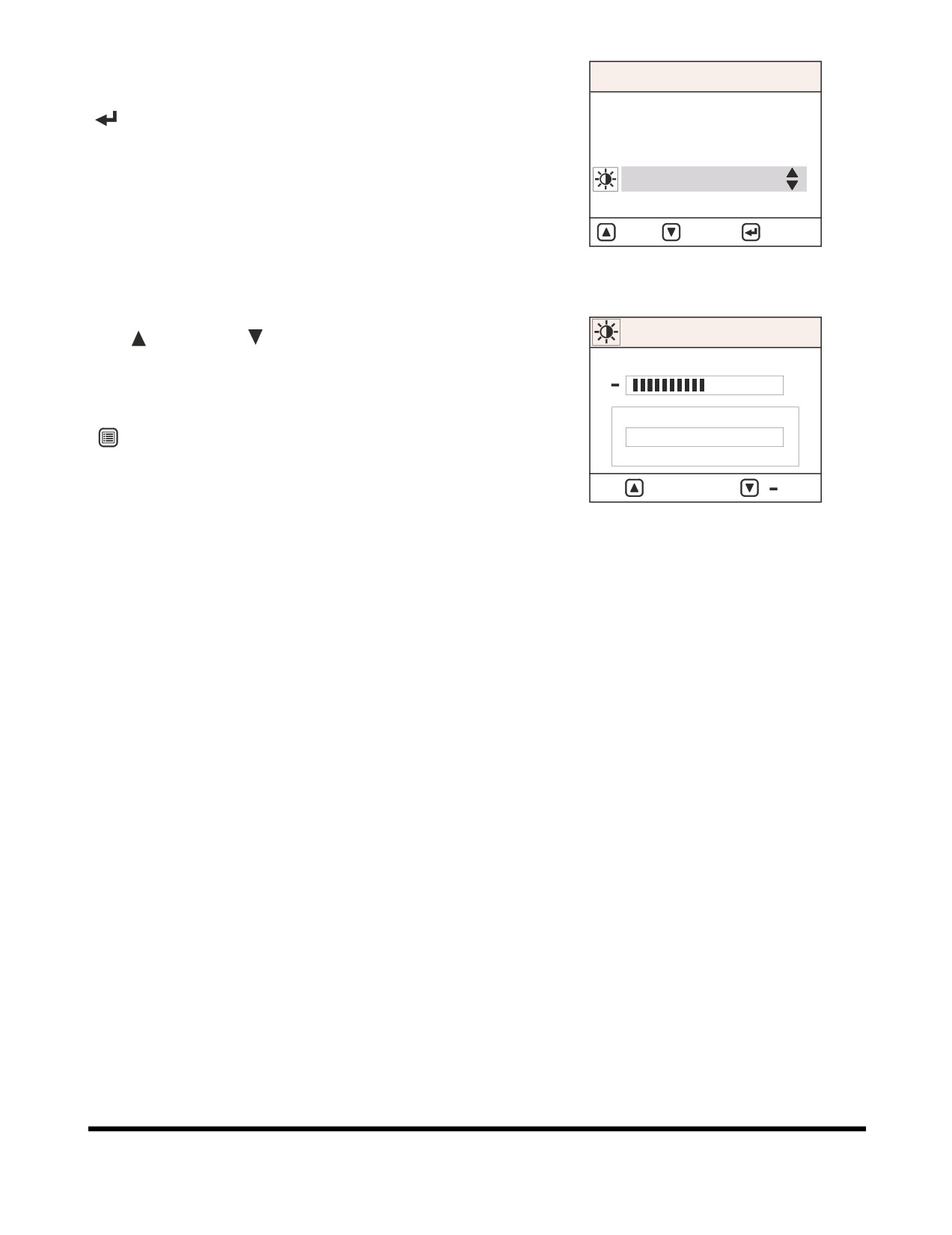
Adjust Display
MAIN MENU
When the cursor is on "Adjust Display," press the "SELECT"
1. Language
(
) button. The adjust display submenu will appear.
2. Set Clock
3. Filter / Oil Info
4. Adjust Display
5. Set Password
: UP
: DOWN
: SELECT
FG000080
Figure 88
The desired brightness adjustment can be selected by using
"UP" (
) or "DOWN" (
) buttons.
Adjust Display
NOTE: When the equipment shipped, the default brightness
50%
is set to 50%.
+
The screen is returned to the main menu by pressing the "ESC"
LCD TEST
(
) button. The display is then saved.
LCD TEST
LCD TEST
: +
:
FG000081
Figure 89
Operating Controls
OP000597
2-44
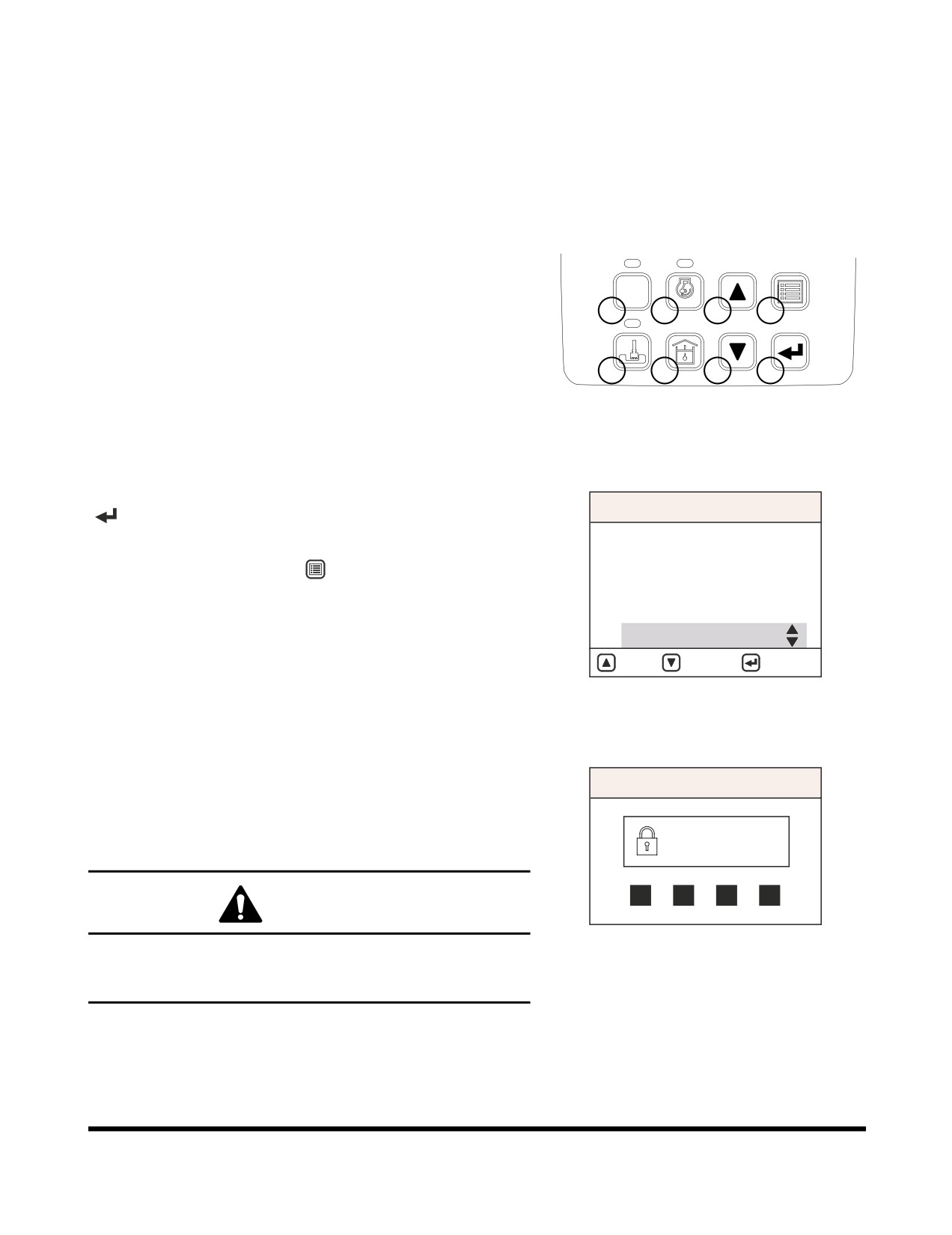
Set Password (Lock and Unlock)
Use extreme care when setting the password for starting the
engine. If a mistake is made when entering the number, and the
number is excepted by the system, as being correct, that
number will be the only one that will allow the security system to
be activated or deactivated.
Write your password down and keep it in a safe location.
Password numbers can only use numbers between 1 and 8. The
small number to the lower left of each button on the instrument
panel, indicates the number that will be entered when that button
is pressed. Numbers "0" and "9" are invalid choices.
POWER
AUTO
1
2
3
4
ESC
Example:
2785 is acceptable.
5
6
7
8
9024 is not acceptable.
HAAE2010
Figure 90
When the cursor is on "Set Password" press the "SELECT"
(
) button. The set password submenu will appear.
MAIN MENU
1. Language
NOTE: The screen can be returned to the main menu by
2. Set Clock
pressing the "ESC"(
) button (3, Figure 72).
3. Filter / Oil Info
4. Adjust Display
5. Set Password
: UP
: DOWN
: SELECT
FG000227
Figure 91
Password inquiry menu will be displayed.
NOTE: The initial password is "1111."
SET PASSWORD
The password can be changed within ten minutes while the
starter switch is in "I" (ON) position.
ENTER
After changing password, be sure to use the changed password.
PASSWORD
CAUTION!
FG000228
Failure to enter correct password three times, will return
Figure 92
normal display screen, and another attempt will not be
possible for ten minutes.
Operating Controls
OP000597
2-45
A three item menu will be displayed. The items are "LOCK,"
"UNLOCK," and "CHANGE PASSWORD." An item can be
selected by using the "UP" (
) or "DOWN" (
) buttons, and
then selected by pressing the "SELECT" (
) button.
Press "ESC" (
) button (3,Figure 72) for 1 more second, it
returns to main menu.
According to the selection of adoption (lock) or nonadoption
(unlock), the password function will be in working or nonworking.
SET PASSWORD
When you want to change a password, follow below procedure.
Lock
1.
Move the cursor to "Change Password."
Unlock
2.
Input desired 4 digits password using selector buttons (at
Change Password
the first column). Input the same password one more time
(at the second column)
3.
Select adoption
(lock) or nonadoption
(unlock) at set
: UP
: DOWN
: SELECT
password menu.
FG000229
NOTE: Keep in mind never to forget password.
Figure 93
NOTE: Please contact a DOOSAN distributor, if you
forget your password.
Operating Controls
OP000597
2-46
FLOW CONTROL
02/05 [MO] 11:30
The flow control is used to set the proper flow rate for an
optional attachment (If equipped). The flow control screen is
accessed directly from the normal display screen without going
E
F
through the main menu or any submenus.
C
H
C
H
E/G SPEED 1700 RPM
FG000043
Figure 94
When the flow control button (Figure
70 and Figure 95) is
pressed at the normal display screen
(Figure
94), the flow
control screen (Figure 97) will be displayed.
6
FG000066
Figure 95
Select a tool by using the breaker / boost / shear selector switch.
The symbol in the upper left corner of the display screen will
change according to the position that the selector switch is in.
I
Compare the symbols shown in (Figure 97 and Figure 98).
O
II
FG000025
Figure 96
Operating Controls
OP000597
2-47
Adjusting Flow Rate
FLOW CONTROL
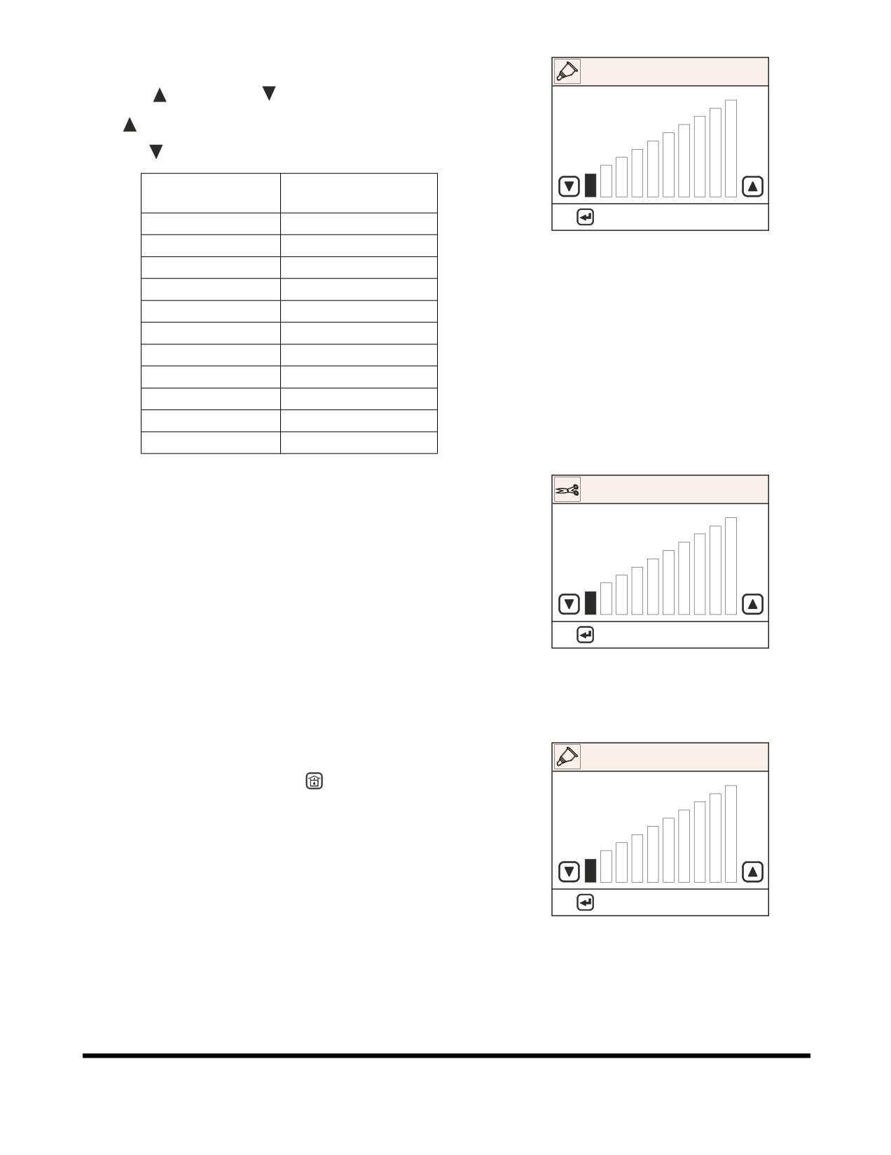
Use "UP" (
) or "DOWN" (
) buttons to adjust flow rate.
"UP" (
) button is used to increase a flow rate.
"DOWN" (
) button is used to decrease a flow rate.
Flow Control
Pump Flow Setting
Step
(l/min)
: APPLY
ESC: CANCEL
0
48.5
FG000254
1
57
Figure 97 Breaker
2
66
3
69
4
78.5
5
90
6
96.5
7
106.5
8
108
9
114
10
114
Pump flow setting is at rated engine speed, for only the output of
one pump.
FLOW CONTROL
Pump displacement will vary according to changes in engine
rpm.
: APPLY
ESC: CANCEL
FG000255
Figure 98 Shear
Escape
FLOW CONTROL
A. Press flow control button
(
, Figure
95) to return to
normal display screen and save the flow rate setting.
B. If there is no adjustment for twenty seconds, the flow
control screen will return to the normal display screen.
: APPLY
ESC: CANCEL
FG000254
Figure 99
Operating Controls
OP000597
2-48
OPERATION SELECTION
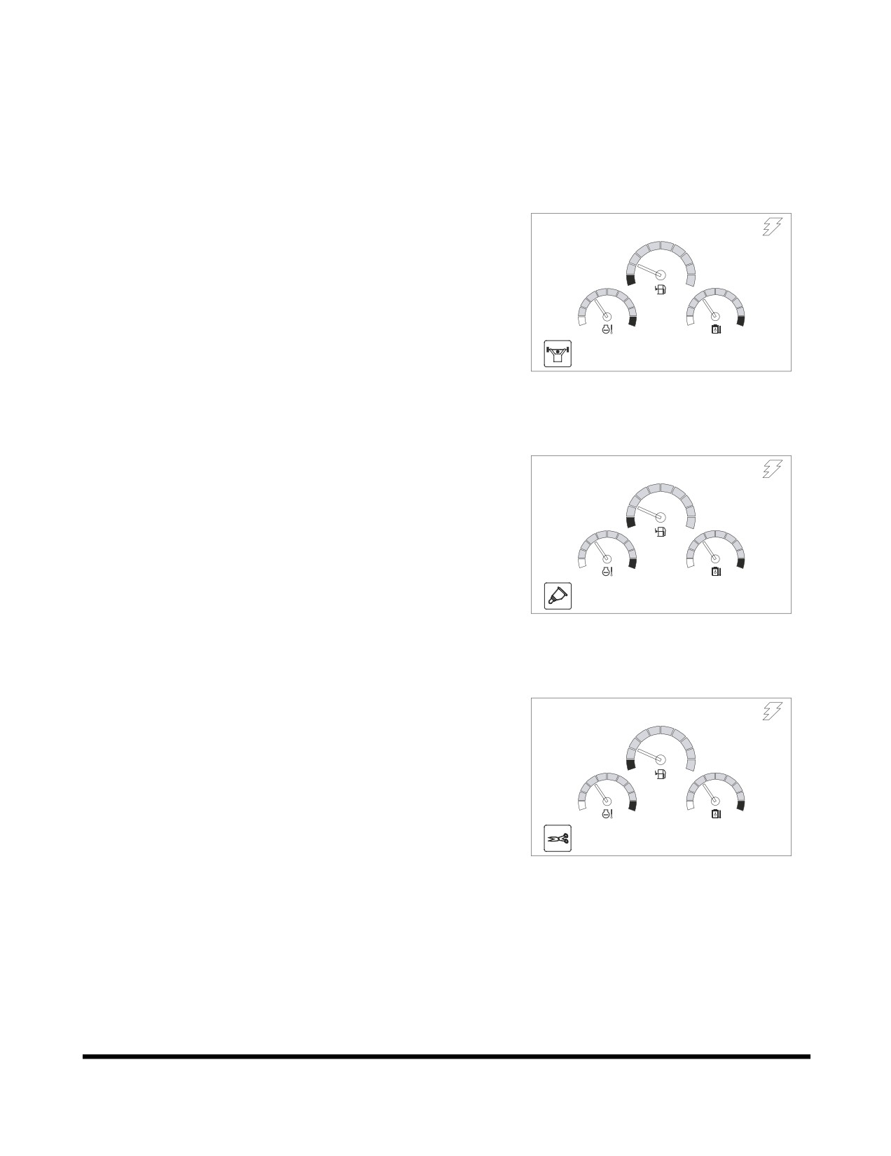
DISPLAY
In the monitor you can see the application that is currently
selected.
Power Boost Selection
02/05 [MO] 11:30
E
F
C
H
C
H
E/G SPEED 1700 RPM
FG000257
Figure 100
Breaker Selection
02/05 [MO] 11:30
E
F
C
H
C
H
E/G SPEED 1700 RPM
FG000258
Figure 101
Shear Selection
02/05 [MO] 11:30
E
F
C
H
C
H
E/G SPEED 1700 RPM
FG000259
Figure 102
Operating Controls
OP000597
2-49
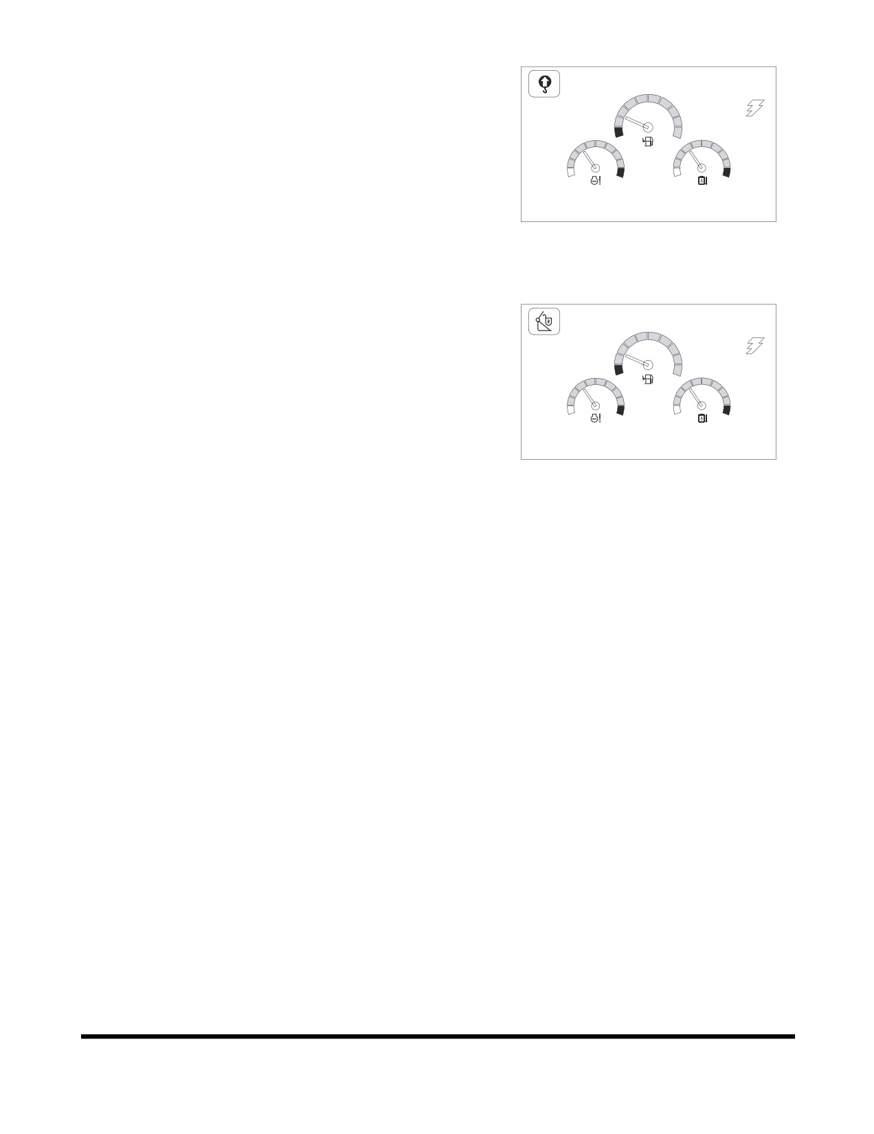
Overload Alarm Selection (Optional)
02/05 [MO] 11:30
E
F
C
H
C
H
E/G SPEED 1700 RPM
FG000260
Figure 103
Quick Clamp Operation Selection
(Optional)
02/05 [MO] 11:30
E
F
C
H
C
H
E/G SPEED 1700 RPM
FG000388
Figure 104
Operating Controls
OP000597
2-50
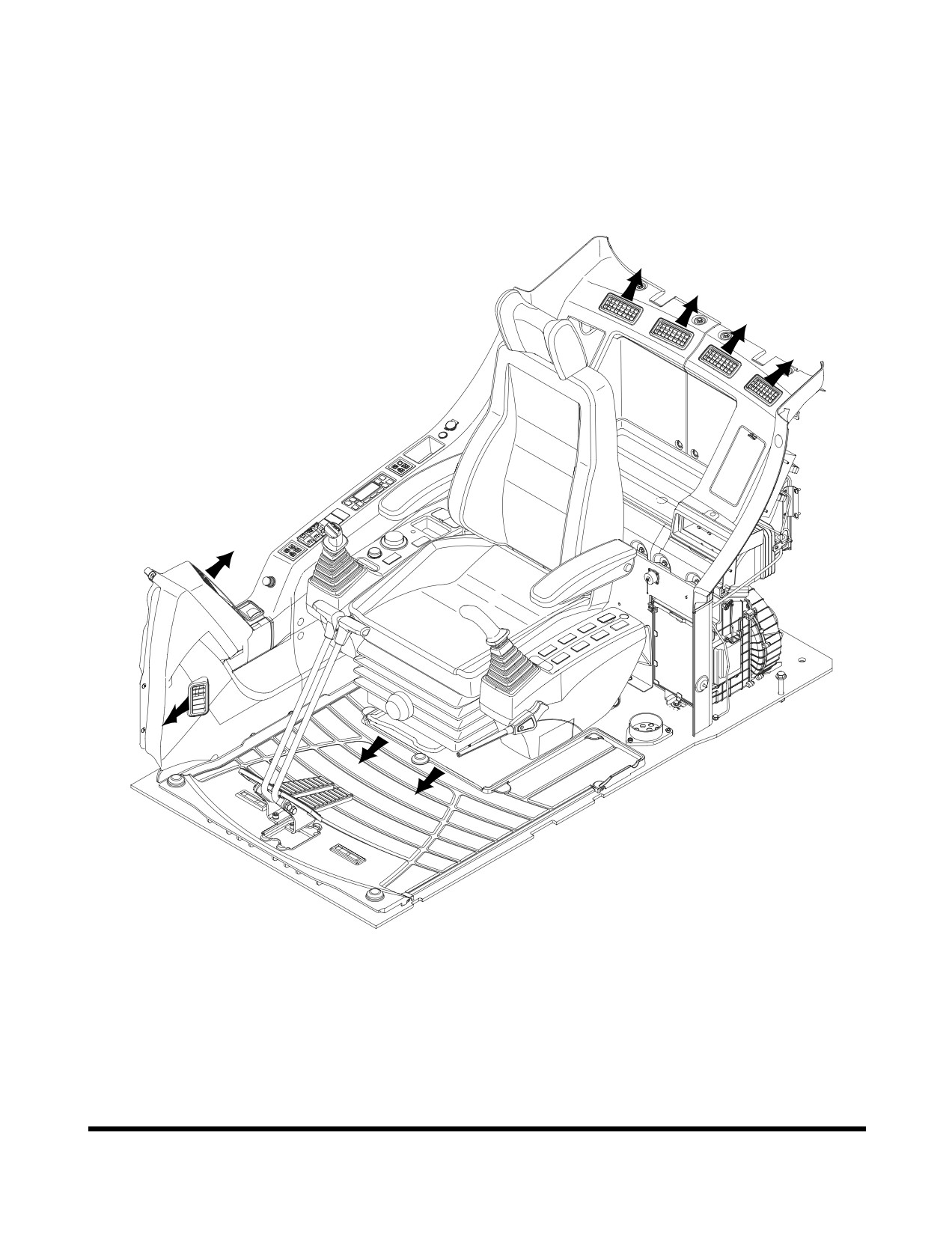
HEATER AND AIR CONDITIONER
CONTROL PANEL
Location of Controls and Vents
FG000288
Figure 105
The heater and air conditioner are combined into one unit in the
rear cover behind the operator's seat.
The operator can control cabin temperature using the control
panel installed in the switch panel.
Operating Controls
OP000597
2-51
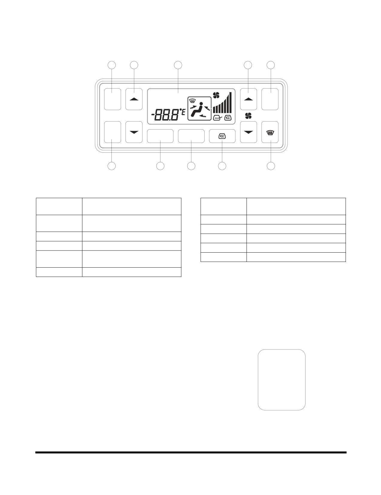
Control Panel
1
3
10
7
8
A/C
OUTSIDE
AUTO
A/C
AUTO
MAX
TEMP
OFF
SEL
MODE
2
4
5
6
9
FG000086
Figure 106
Reference
Reference
Description
Description
Number
Number
1
Automatic Temperature Control
6
Air Inlet Selector Button
Button
7
Fan Speed Selector Button
2
Off Button
8
Air Conditioner Button
3
Temperature Control Button
9
Defroster Button
4
Temperature Unit Selector
10
LCD Display
Button
5
Air Outlet Selector Button
NOTE: When the light switch is turned to "I" or "II" position,
the LED for illuminating in the control panel will turn
"ON."
1.
Automatic Temperature Control Button
This button is used to control the temperature level in the
cabin, according to the temperature setting of the operating
panel.
When the automatic temperature control function is
AUTO
activated, the word "AUTO" will be displayed in the upper
left of LCD display.
When the system is in "AUTO" mode, specifications can be
manually changed by pushing another button.
FG000088
If a function is manually changed, the word "AUTO" does
Figure 107
not appear in the LCD display, but the unchanged
functions will remain in "AUTO" mode.
Operating Controls
OP000597
2-52
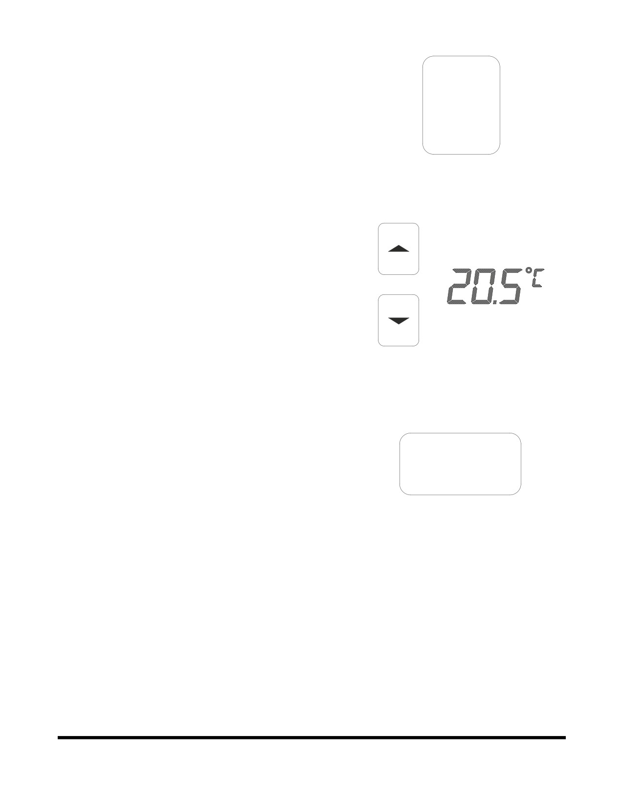
2.
Off Button
This button is used to stop the fan and air conditioner.
OFF
FG000089
Figure 108
3.
Temperature Control Button
These buttons are used to control the cabin temperature.
Temperature is adjustable from 17°C (62°F) to 32°C (90°F)
by 0.5°C (1°F) increments.
Temperature setting is displayed on the LCD.
TEMP
When the system is turned "ON," the previously set
temperature is used as a starting point.
FG000090
Figure 109
4.
Temperature Unit Selector Button
This button gives the choice to select either °C or °F.
SEL
FG000094
Figure 110
Operating Controls
OP000597
2-53