CG958H Wheel Loader. Manual - part 18
 

  Index      loaders     SICHUAN CHENGDU CHENGGONG CG958H Wheel Loader - service manual


Search            


Content   ..  16  17  18  19   ..


CG958H Wheel Loader. Manual - part 18


-  - 

74

1.3.4 Cooling fan control system 

I. Structure and operating principle of cooling fan control system 

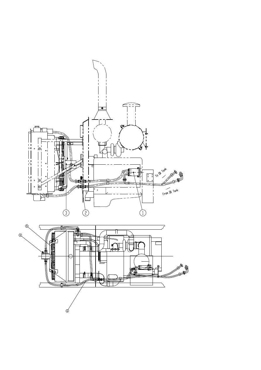
1. Diagram of cooling fan control system 


(1). Pump: CBQz-F540-AFΦL, (2). Pressure tap: measures motor inlet pressure, (3). Hydraulic 

motor: WM09A1C310L07TB122HGNNR2320001M, (4). Overflow valve: provided with hydraulic 

-  - 

75

motor, (5). Motor support assembly, (6). fluid coupler 

2. CG958H loader adopts an independent cooling system (cooling fan control system) mainly 

consisting of pump, motor, motor support assembly, coupling flange, fluid coupler, etc., system 

cleanliness is controlled within Grade NAS1683 9. 

Features of cooling fan control system: 

(1). Better cooling effects on hydraulic oil and torque converting oil; 

(2). Cooling effects on hydraulic oil and torque converting oil are not affected even under loaded 

working conditions of the loader. 

System cleanliness is controlled within Grade NAS1683 9. 

II. Pump: CBQz-F532-AFΦL manufactured by Hefei Changyuan Hydraulics Co., Ltd. 

Position of pump: 


CBQz-F532-AfΦL gear oil pump adopts high strength aluminum alloy for pump casing, and uses 

many advanced technologies such as axial clearance floating compensation, radial equilibrium, DU 

self-lubrication, etc. It features high volumetric efficiency, high pressure, low noise, good vibration 

resistance and long service life. 


IMPORTANT 


Dismounting and servicing of gear pump by untrained maintenance staff is strictly 

prohibited. 


-  - 

76

CAUTION 


When replacing rubber tube assembly in gear pump, loader engine should be shut off first to 

release pressure and cool down hydraulic oil (to a safe degree) before the replacement is made. 

III. Motor: WM09A1C310L07TB122HGNNR2320001M manufactured by Haldex international 

trade (Shanghai) Ltd. 


Position of motor 


IMPORTANT 


Discounting and servicing of motor by untrained maintenance staff is strictly prohibited. 


CAUTION 


When replacing rubber tube assembly in motor, loader engine should be shut off first to 

release pressure and cool down hydraulic oil (to a safe degree) before the replacement is made. 

IV. Safety marks 

All safety marks and meanings thereof for cooling fan control units will be described here. 

Operators must read carefully and understand completely these descriptions, which should be 

complied with in operation and maintenance. If any mark is damaged, lost or illegible, replace 

it with a new one. 

-  - 

77

II Cab Facilities 

2.1 Instrument Desk and Accessories


1.  Engine failure signal light 

2.  Working rotation indicator 

3.  Emergency warning light 

4.  Emergency steering signal light 

5.  Engine waiting signal light 

6.  Signal light for water in engine fuel   

7.  Engine shutdown light 

8.  Remote indicator 

9.  Charging indicator- Indicating the engine and charging system’s work 

10. Absorber signal light 

11. Parking signal light 


Content   ..  16  17  18  19   ..