CG958H Wheel Loader. Manual - part 16
 

  Index      loaders     SICHUAN CHENGDU CHENGGONG CG958H Wheel Loader - service manual


Search            


Content   ..  14  15  16  17   ..


CG958H Wheel Loader. Manual - part 16


-  - 

66

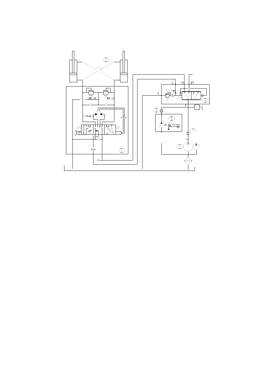
1.3.3 Description of steering hydraulic system 

I. Principle: 


II. Components: 

1. Pump: T6DCM-B24-B05-3R23-C1 

    Manufacturer: 

Denison USA


2. One-way valve: DIF-L32H 

    Manufacturer: Huade Hydraulic Parts Factory 

3

. Emergency steering power unit: 12869-00


    Manufacturer: Haldex Sweden 

4. One-way valve: S25A02 0B 

Manufacturer: Huade Hydraulic Parts Factory 

5. Priority valve: VLE-150/882-5902-059 

    Manufacturer: Eaton 

6.

 Steering gear

: BZZ1-1250(FK-0/20)550-7286/831-2604 

    Manufacturer: Eaton 

7. 

Steering cylinder: 

 CL90X45/488 EG-00A 

        Manufacturer: Chengdu Hailingda Hydraulic Technology Co., Ltd.


III. System description   

Pilot oil source   


  Brake pump 

To Multi-way valve

-  - 

67

Steering system adopts a load-sensing hydraulic steering mechanism mainly consisting of 

pump, load-sensing steering gear, priority steering control valve, steering cylinder, emergency 

steering power unit, check valves and pipelines. LS pipeline transfers internal pressure signal from 

steering gear to priority valve to achieve balance of the valve plug, thus ensuring the flow rate 

required by port CF. When the pressure at the outlet of the steering pump is less than 8 bars, the 

pressure switch installed at the outlet will close to drive the emergency steering power unit to 

realize the function of emergent steering. 

III. Description of Components 
1.


Pump: Denison T6DCM-B24-B05-3R23-C1, position is shown in the figure below: 


Denison vane pump meets SAE and IOS 

standards. Hydrocushion design ensures long 

service lives of shaft and bearing with extremely 

small noise and high volumetric efficiency. The 

main internal structure is as shown in the right 

figure.


  Outlet 

Rotor 

  Vane 

 Inlet 

Flow passage to 

vane root 

  Figure 1 


Continuous outlet pressure 


I

nlet pressure or 

outlet pressure 

Figure 2 

-  - 

68

 IMPORTANT 


Dismounting and servicing of vane pump by untrained maintenance staff is strictly 
prohibited. 


CAUTION 


When replacing rubber tube assembly in vane pump, loader engine should be shut off 

first to release pressure and cool down hydraulic oil (to a safe degree) before the 

replacement is made. 

2. Steering gear: Eaton BZZ-1250


static (splined connection) 

a Operating principle: the functionality is realized by a load-sensing system. The flow rate 

going through steering gear is quite low when steering gear is in neutral position to keep constant 

pressure and save energy for the system. During power steering, pressure oil enters stator through 

valve plug and valve bush, and pushes the rotor to rotate with steering wheel to transfer the oil 

pressure to the left or right chamber of steering cylinder, thus realizing steering by pushing guide 

wheel with cylinder piston rod. Oil in the other cylinder chamber returns to oil tank through steering 

gear. 

b Installation: 

Make sure that steering gear installed is 

coaxial to steering post with clearance kept in 

axial direction to avoid dieback of valve plug. 

Check steering wheel to see if opposite 

rotation is smooth after installation. 

c  Pipelines should be installed as per 

the four oil ports marked on steering gear: 

“P” – to be connected with oil pump; 

“T” – to be connected with oil tank; 

“A” and “B” are to be connected with 

-  - 

69

left and right chamber of steering cylinder respectively. 

d    Structure of steering gear is given in the right view: 

e Diagram of FK combination valves: 


Position of steering gear 


IMPORTANT 


1. Be careful not to bump or scratch the working surface or end surface of various parts. 

2. Do not soak the dismounted rubber ring in gasoline to avoid deformation or deterioration due 

to action between rubber and gasoline. 

1 Safety valve plug, 2 Pad, 3 Valve body, 4 Pressure controlled valve plug of safety valve, 5 Spring, 6 Safety 

valve assembly, 7 Overload valve plug, 8 Pad, 9 Overload valve seat, 10 Sealing ring, 11 Spring, 12 Overload 

oil-supplying valve assembly, 13 Valve seat, 14 O-ring, 15 Inlet single-way valve assembly, 16 Locknut 


Content   ..  14  15  16  17   ..