CG958G Wheel Loader. Manual - part 22
- 92 -
is not available, the cable cathode (-) of the external power source shall be connected with the
body of the engine.
3) Fuse box
Fuse box--Installed at the left lower side of the cab meter panel.
Fuse--protecting the electrical system from the damage due to circuit overloading. The damaged
fuse shall be replaced; in case the same new fuse is blew upon replacement, the circuit shall be
examined and repaired.
Caution
In replacement, the fuse of same model and specification is required, or not the circuit will
be damaged possibly. In case frequently replacement
of the fuse is required, the circuit is involved in
failure possibly. The circuit shall be examined.
2.3 Air conditioning System
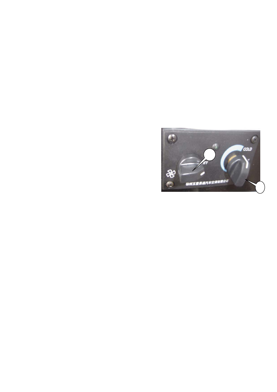
Basic operating method
Refrigeration (1) For the first time the cooling system
is used, blowing rate switch shall be rotated to
the high speed after the engine is started (at this time, the indicator lights), and run for five
minutes.
(2) Rotate the temperature control switch clockwise to “COLD”. At this time, the cooling
system starts work.
(3) When the temperature is decreased to the required one, rotate the temperature control switch
anticlockwise slowly until the indicator off. (At this time, the temperature is the one set. The
air conditioning system will regulate the temperature automatically).
(4) As the cold air is used in high temperature seasons, windows and doors shall be closed, or
not the refrigeration effect will be weakened.
Note: In refrigeration, please shut off the heat water valve
Heat supply (1) Turn off the temperature control switch to OFF, turn on the heat water valve and
start the blowing rate switch.
(2) Appropriate temperature may be attained by regulating the heat water valve.
As the engine fails to work for ambient temperature less than 0 , the engine radiator shall be
℃
emptied or filled with anti-icing fluid so as to avoid the breakage of the pipe of the radiator of
1 Blowing rate switch 2 Temperature control switch
1
2