CG958G Wheel Loader. Manual - part 20
- 84 -
1.3.4 Cooling fan control system
I. Structure and operating principle of cooling fan control system
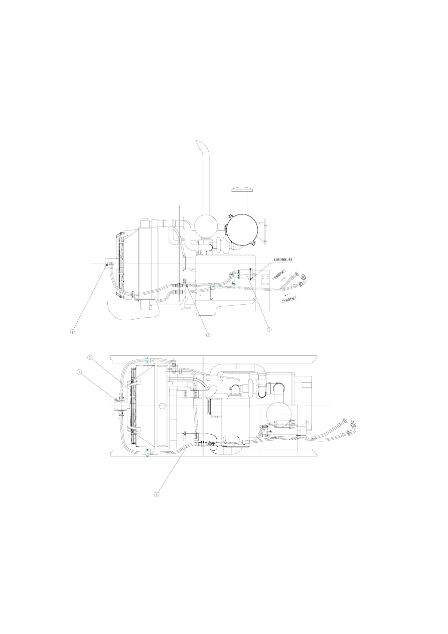
1. Diagram of cooling fan control system
(1). Pump: CBQz-F540-AFΦL, (2). Pressure tap: measures motor inlet pressure, (3). Hydraulic motor:
WM09A1C310L07TB122HGNNR2320001M, (4). Overflow valve: provided with hydraulic motor, (5).
Motor support assembly, (6). fluid coupler
2. CG958G loader adopts an independent cooling system (cooling fan control system) mainly consisting of