1t-3.5t R Series Internal Combustion Counterbalanced Forklift Truck. Manual - part 19
 

  Index      Engines     HANGCHA 1t-3.5t R Series Internal Combustion Counterbalanced Forklift Truck - manual 2011 year


Search            


Content   ..  17  18  19  20   ..


1t-3.5t R Series Internal Combustion Counterbalanced Forklift Truck. Manual - part 19


72 

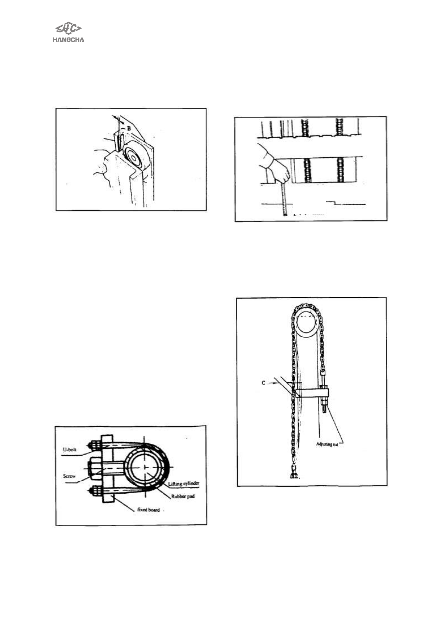
Clearance  of  back  up  metal  and  mast 
steel 
Adjust clearance ―B‖ to 0.1mm~0.8mm 
with  shims,  which  may  not  use. 
Thickness of shim is 0.5mm or 1mm. 


Apply  a  coat  of  grease  to  back-up 
metals.  Install  mast  and  lifting  jack  on 
forklift  truck.  Connect  circle  tube  and 
high-pressure tube. 
4.4  Left  and  right  cylinder  height 
adjustment. 
1) Install  left  and  right  lifting  jack  on 
mast,  pin  must  be  installed  into 
orientation hole of outer mast lower cross 
beam. 
2) Install  upper  of  piston  rod  on  inner 
mast.  Inner  mast  lay  evenly  in  the 
direction of left, right, upper and lower. If 
it  is  not  even,  please  adjust  by  putting 
washer between hole of cylinder support 
and upper end of piston rod. 
3 Installs 

U-bolt 

onto 

cylinder, 

hand-tighten  nuts  and  lock  it  with  two 
tighten  nuts.  Screws  down  tighten  bolt 
and nuts to avoiding loosing. 


4.5 Lifting chain adjustment 

Installs fork arm carrier on inner mast, 

and  install  lifting  chain,  then  install  two 

nuts on end of every side. With mast set 
straight  up,  lower  carriage  completely. 
Temporarily  adjust  clearance  of  carriage 
to  74mm-76mm  above  ground.  If 
necessary,  adjust  with  chain  adjusting 
nut. 


To  adjust  tension  of  lift  chain,  lower 
lifting  jack  until  fork  is  on  the 
ground  ,and  adjust  chain  adjusting  nut 
(three  every  side)  so  that  dimension  C 
will be as listed below when the middle 
portion of chain is pressed by a finger. 

Dimension C: 25mm~30 mm 


4.6  Clearance  of  fork  arm  carrier 
assembly and rollers adjustment 
1) Measure insid

e width ―A‖ between 

inner masts. Make measurements at 
the top, bottom and center (cross beam) 
sections. 

74 mm 


73 

2) Measure right and left 
pitches,B,B

′,B" of carriage side roller, 

carriage roller and thrust metal. 
3) Calculate A-B, A-B

′and A- B".Each 

result shows clearances between each 
roller and inner mast. Adjust shims of 
each roller evenly on the left and right 
and make clearances, between 
smallest part of inner mast and carriage 
side roller. 

– B = 0.2mm~1 mm 

A - B

′ = 0.1mm~0.8 mm 

A - B "= 0.1mm~0.8 mm 


Shims   
0.5 mm  


1 mm 

a.  Number  of  shims  must  be  the  same 

on  the  right  and  left  sides,  when 
using shims. 

b.  After  clearance  adjustment,  push 

carriage  assembly  to  see  if  it 
operates properly. 


5. Disassembly and installation of 
lifting jack 

!

WARNING   

Keep body away from equipment 
1) Turn  out  engine,  then  make  lifting 

jack  falling  into  lowest  condition  that 
lower  of  piton  rod  is  touched  bottom 
of  cylinder  body  so  as  to  oil  flowing 
back tank completely. 

2) Unscrew piston rod and bolt. 
3) Disconnect  circle  oil  pipe,  remove 

high pressure tubes.       

4) Remove  U-bolt  of  outer  mast 

fixation  board  and  tighten  skew  of 
other side. 

5) Remove chain of outer mast. 
6) Attach  wire  rope  to  inner  mast  and 

remove  left  and  right  lifting  jack  with  a 
lifting device. 


74 

5.1 Disassembly 
Rated capacity is less than 2.5 t   
 

Remove  cylinder  head  and  guiding 

bush 
Rated capacity is more than 3 t 
 

Removes  tighten  skew  and  nylon 

stopper, then remove cylinder head. 
1) Remove dust gasket ring. 
2) Remove Y-ring with screwdriver. 


CAUTION:Please not use dust gasket 

ring removed, O-ring, Y-ring again, 
must replace.   

3) Draw out piston rod , remove Y-ring 

on end of piston.     

5.2 Install and replace faulty parts. 

1) Cleanup parts  with  clean  oil  before 

installation. 

2) Then  cleanup  guiding  bush  and 

piston with hydraulic pressure oil the 
same as oil box trademark. 

3) 

Dust  or  dunghill  doesn’t  drop  into 

lifting jack. 

4) The  order  of  installation  is  reverse 

the order of disassembly. 

5) Install Y-ring on piston. 
6) Install  piston  rod  assembly  into 

clean cylinder body.           

CAUTIONThe end of cylinder body 
mast  slick  and  clean,  installation 
must  set  center,  avoid  scratching 
Y-ring.
 
7) Install  replacing  dust  gasket  ring 

and  Y-ring  in  guiding  bush  and 
cylinder head. 

NOTICE : Apply  hydraulic  pressure 
grease which trademark is the same as 
tank  on  guide  sleeve  installed    gasket 
ring   
8) Rip  cylinder  head  into  piston  rod, 

screw down cylinder body. 


6.Disassembly and installation of 
tilting cylinder 


!

WARNING 

Noticing  proceedings  when  removing 
cylinders. 
·

Attach  wire  rope  to  outer  mast, 

avoiding  mast  fall  down  after  removing 
tilting cylinder. 
·

Keep  body  away  from  equipment,  no 

standing under the fork arm carrier. 
1) Lay 

down 

fork 

arm 

carrier 

completely. 
2) Remove  bolt  on  the  left  and  right 
bracket  of  outer  mast,  moreover  pull 
axis out. 
3) Remove oil pipe to the inlet of tilting 
cylinder. 
4) Remove  bolt  on  the  bracket  of 
Chassis,  and  pull  pin  out,  then  move 
tilting cylinder. 
5) The  order  of  installation  is  reverse 
the order of disassembly. 


75 


6.1 Disassembly of parts 
1)  Squeeze  tilting  cylinder  with  pliers, 
then  pull  piston  rod  come-and-go  as 
opening of inlet and outlet on the tilting 
cylinder,  so remaining oil is discharged 
tilting cylinder. 
2)  Screw  earring  bolts  2  loosely,  and 
screw earring 1 out. 
3)  Remove  cylinder  head  guiding  bush 

3; 

4)  Draw out piston rod assembly 4 (see 

as follows). 


5) Remove all dust gasket rings, O-ring 
and Y-ring. 
6)  Remove  dust  gasket  ring  in  the 
cylinder  head.  Means  is  the  same  as 
discharging  of  dust  gasket  ring  in  the 
cylinder  head  of  lifting  jack  (see 
disassembly  and  installation  of  lifting 
jack). 
7) Remove O-ring outside in the guiding 
bush. 


8)  Remove  O-ring  and  Y-ring  in  the 
inner  hole  of  guiding  bush  (see  Fig. 
disassembly  and  installation  of  lifting 
jack). 
CAUTION:No  using  dust  gasket  ring 
and Y-ring removed. 
 
6.2  Install  tilting  cylinder  after 
replacing ring 
The  order  of  installation  is  reverse  to 
the  order  of  disassembly,  but  should 
notice follow proceedings: 
1) Lubricate parts with clean hydraulic 
pressure oil. 
2) Avoid  dust  and  oil  dirty  dropping 
into tilting cylinder. 
3) Avoid scratching the end of cylinder 
body, and    inlet and outlet for oil. 
4) Push  piston  rod  to  cylinder  body 
when  setting  center,  especially  avoid 
scratching Y-ring. 
5) Before installing guiding bush, wipe 
hydraulic 

pressure 

oil 

backing 

boardched 

with 

employment 

oil 

trademark  in  the  middle  of  O-ring  and 
Y-ring in the inner hole of guiding bush. 
6) 

Don’t  scratch  O-ring  outside  in  the 

guiding bush when installing. 
7) Remember  install  nylon  stopper 
and  tighten  screw  after  screw  cylinder 
head. 
 

7. 

Noticing 

proceeding 

of 

debugging   

1) Adjust  Forward  and  BackWard  of 
the mast 
Place fork lift truck on the level ground, 
operate  control  lever  to  realize  that 


Content   ..  17  18  19  20   ..