1t-3.5t R Series Internal Combustion Counterbalanced Forklift Truck. Manual - part 18
 

  Index      Engines     HANGCHA 1t-3.5t R Series Internal Combustion Counterbalanced Forklift Truck - manual 2011 year


Search            


Content   ..  16  17  18  19   ..


1t-3.5t R Series Internal Combustion Counterbalanced Forklift Truck. Manual - part 18


68 


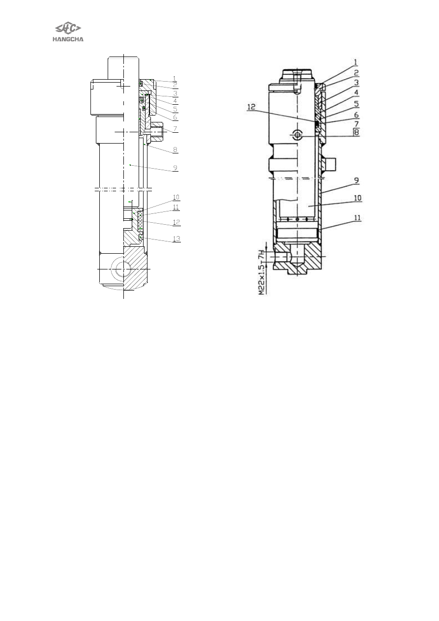
Fig.8-9   

Lifting cylinder (left) 

(used in fig.10-2,10-3) 

1. Cylinder cover    2.dustproof ring 
3. Adjusting washer 4. Guide sleeve 
5.ISI-ring      6.  O-ring  7.compound  sleeve       
8. Cylinder 9. Piston rod 10.piston     
11.support ring        12.OSI-ring 

Fig. 8-10    free lifting cylinder 

(used in 8-2、8-3) 

1. Dustproof ring 2. Cylinder cover 
3.Guide sleeve          4.O-ring 
5.O-ring    6.seal ring      7.deflation plug 
8. O-ring 9. Cylinder assembly   
10. Plunger rod 11. Support ring   
12. Stop ring 


Less than or equal to 

2.5t cylinder 


69 

4. Removal and adjustment 

!

WARNING 

Be careful when removing and installing 
the forks, carriage and mast as they are 
heavy. 
4.1 

Remove 

forks 

and 

mast 

assembly 
1) Unlock  fork  lock  pins  by  pulling 
them  and  move  forks  to  cutout  portion 
in  the  middle  of  carriage  bracket 
assembly. 
2) Pull lower portion of fork to remove 
its lower jaw and lift it out. 

!

WARNING 

a.  Keep  hands  and  feet  away  from 
forks  when  removing  and  installing 
forks  carefully,  keep  feet  and  hands 
clear. 
b.  Do not remove forks from the end of 
the fork bar.    Severe injury can result if 
the fork is dropped. 


1) Attach  wire  ropes  to  carriage 
bracket  assembly  and  lift  carriage 
bracket  assembly  up  with  a  lifting 
device. 
2) Remove  chain  attaching  nuts,  and 
detach  chains  from  carriage  bracket 
assembly. 


3) Remove carriage bracket assembly 
from inner mast. 
4) Detach high pressure hose, lift hose 
and low pressure hose. 


5) Support  mast  assembly  with  wire 
ropes. 


6) Pull out tilt cylinder pivot pin. 


7) Remove mast support caps. 


70 


8) Remove mast assembly. 
9) To  install  mast  assembly,  reverse 
order of removal. 
4.2 Disassembly 

!

WARNING 

Be  careful  when  disassembling  the 
masts as they are heavy. 
Remove lifting jack 
1) Place mast flat on ground. Remove 
lifting  jack  attaching  bolts-bolts  and 
tighten screw. 


2) Slide inner mast, then remove lifting 
cylinders. 
Remove roller 
1) Slide inner mast out until rollers are 
exposed  and  remove  little  rollers  with 
bearing puller. Make two pieces of round 
board  about  10mm  thick  and  their 
diameter are Ф53 and Ф58, covered on 
the  seat  of  roller.  Then  remove  the 
compound  roller  and  main  roller  with 
bearing puller. 
2) Unclench  rollers  carefully  if  no 
bearing  puller  or  rollers  would  be 
smashed. 


Remove inner mast 

Attach  wire  rope  to  middle  of  inner 

mast  and  slide  it  out  with  a  lifting 
device. 


INSPECTION 
1) Check  lift  rollers,  roller  shafts,  and 
associated parts for wear or damage. 
2) Replace 

damaged 

parts 

as 

required. 
4.3 Assembly and adjustment 

!

WARNING 

      Be  careful  when  assembling  the 
masts as they are heavy. 
Lift roller 
    Slide  inner mast  into  outer  mast  and 
securely attach lift rollers. 


71 


Lift 

roller-to-mast 

clearance 

adjustment 
 
1) Set  roller  pitch  of  inner  and  outer 
masts  to  ―L‖  dimension.  Then  proceed 
with the following adjustment. 
Dimension ―L‖                            unit:mm 

          Model   

or    tonnage 

Max.lift       
height    (mm) 

Ⅲ 

grade 

3 t 

Ⅱgrade 

2t~2.5t 

2500~3300 

368 

328 

3600 

388 

348 

4000 

418 

378 

4500 

443 

403 


2) 

Adjustable range ―A‖ with shims: 

a.  Dimension:0.1mm~0.6mm.(≤2 t) 


b.  Dimension:0mm ~ 0.5mm  (2.5t ~ 3 
t).One or two may not using rubber pad; 
Dimension:0.1 ~ 0.6mm  if  no  rubber 
pad. 
Orientation pin ensure that side roller is 
vertical to inner mast track. 


3) It is suitable that clearance of roller 
and outer mast is about 0.8mm~1mm. 
Clearance can’t adjustable. Replace it if 
roller wear too much. 
4) Apply lubrication (butter) to interface 
of  inner  mast  and  outer  mast,  interface 
of roller and mast. To prevent sand from 
entering,  it  is  decided  whether  to  apply 
lubrication or not in the area where sand 
blown by wind heavily. 


Content   ..  16  17  18  19   ..