1t-3.5t R Series Internal Combustion Counterbalanced Forklift Truck. Manual - part 12
 

  Index      Engines     HANGCHA 1t-3.5t R Series Internal Combustion Counterbalanced Forklift Truck - manual 2011 year


Search            


Content   ..  10  11  12  13   ..


1t-3.5t R Series Internal Combustion Counterbalanced Forklift Truck. Manual - part 12


44 

2. Summary 

The brake system is the front two-wheel braking type consisting of a master cylinder, brakes 

and brake pedal. 

2.1 master cylinder 


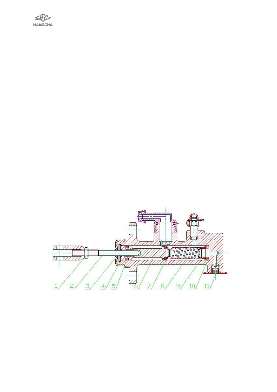
The  2t-3.5t  master  cylinder  contains  a  valve  seat,  check  valve,  return  spring, 

primary cup, piston and secondary cup, which are kept in place with stop washer and 
stop wire. The exterior of the cylinder is protected from dust by means of a rubber dust 
cover.  The piston is actuated through the push rod by operation of the brake pedal. 
First, as the brake pedal, the push rod pushes the piston forwards. The brake fluid in 
the cylinder flows back to the reserve tank through the return port until the primary cup 
blocks up the return port. After the primary cup passes the return port, the brake fluid 
in  the  cylinder  is  pressurized  and  opens  the  check  valve,  flowing  through  the brake 
lines to the wheel cylinder. Thus, each wheel cylinder piston is forced outwards. This 
brings  the  brake  shoes  into  contact  with  the  wheel  drum  and  slows  or  stops  the  lift 
truck..  Meanwhile,  the  cavity  caused  behind  the  piston  is  filled  with  brake  fluid  led 
through the return port and inlet port to lubricate the piston. When the brake pedal is 
released, the piston is forced back by the return spring. At the same time, the brake 
fluid in each wheel cylinder is pressurized by the force of the brake shoe return spring, 
thus returning into the master through the check valve. With the piston in its original 
position,  the fluid  in  the  cylinder  flows  into  the  reserve  tank  through  the  return  port. 
The  brake  fluid  in  the  brake  lines  and  wheel  cylinders  has  a  residual  pressure 
proportioned(about  0.04MPa)  to  the  set  pressure  of  the  check  valve,  which  makes 
each wheel cylinder piston cup securely seated to prevent oil leakage and eliminates 
of vapor lock developing when the lift truck is sharply braked. 

Brake principle of brake master cylinder of 1t-1.8t forklift is similar.     


1. Lock nut  2. Rod      3. Duct cover  4. Light spring      5.    Gasket ring          6. Piston     

7. Primary cup 

  8. Spring 

      9. Raffinate valve        10. Valve seat       11. Cylinder body 

Fig. 6-1 Master cylinder 


45 

2.2   Brake 
1t-1.8t  ,3t-3.5t  forklift  right  hand  structure,  please  see  fig.  6-2,  2t-2.5t  structure  of 
forklift hand brake is similar to 3t-3.5t. 


1. Brake mount bracket    2. Wheel cylinder body 3. Cylinder return spring  4. Rubber cap 

5.Piston 

6.Cylinder dust cover    7. Push rod 

8.Air bleeder cap 

9.Air bleeder screw 

10. Brake shoe assemble (front) 


11. Brake shoe assemble (rear) 

12. Guider 

13. Adjuster cable 

14.Adjusting bolt   

15. Pawl 

16.Spring                17. Brake shoe return spring 

18.Return spring 

19.Parking brake rod 

20.Strut level 

21.Spring 

22.Bolt 

23.Washer 

24.Snap ring 

25.Guider 

26.Spring support rod 

27.Spring bracket 

28.Spring 

29.Plug 

30.Oil connector 

31.Bush 

32.Brake steel cable 

33.pin 


Fig. 6-2    1t~1.8t,3t~3.5t forklift truck right brake 


46 

2.3 Replace brake shoe: 
1)  Place the forklift truck on level concrete. 
2)  Start engine and raise carriage about 100mm. 
3)  Place chocks behind rear wheels to prevent movement of forklift truck. 
4)  Loosen wheel nuts two or three turns each. 
5)  Tilt mast fully backward, and place a wooden block under each side of outer mast. 

!

WARNING 

Do not allow wooden blocks to touch front tires. 

6)  Tilt mast forward until front tires are raised from surface. 
7)  Support forklift truck by putting additional wooden blocks under each side of 
front-end frame. 
8)  Stop engine. 
9)  Remove wheel tire nuts and brake drum. Remove half-shaft, lock nut, and washer. 
10) Remove wheel hub and brake drum. 
11) Replace brake shoes with new ones. 
12) Install brake drum. 
13) Adjust shoe to drum clearance: rotate wheel counterclockwise and at the time 
press down brake pedal several times. 
14) Take out every padding block:take out according to reverse procedures when 
inserting. 
15)   Make sure no person or obstacle is around forklift, then operate forklift in reverse 
at 2km/h to 3km/h, set foot on brake pedal 2~3 times. 
16)  
2.4 Hand brake device 
The hand brake device adopts a hand-pulling soft brake wire cable device. It makes 
use of auto-assist pressure linings type brake together with foot brake. Only when 
parking truck, use the hand brake. If it occurs for foot brake malfunction, use hand 
brake to stop the truck. 
Make sure that drive system is working normally before adjusting hand brake. 
1) Adjust nut B to make the length is 68mm, and then lock nut B. 
2)   Adjust nut A to adjust hand brake pull force, the pull force of    point P in Q 
direction    is in the range of 147N~196N when locking hand lever. 
3) After adjusting hand brake lever correctly, loosen hand brake lever, make sure 
brake loose completely.   
4)   Make sure hand brake device work normally.   
Notice: wipe lithium lubricating grease on guide rail C, and do it usually. 


47 


Fig. 8-3        hand brake   

T torque:9.1-11.8 

Lasso of brake 

Slope:  less 
than 2 mm


Release   

Brake   

Handle   

Adjust  bolt  of 
tension 

T N.m 


Content   ..  10  11  12  13   ..