1t-3.5t R Series Internal Combustion Counterbalanced Forklift Truck. Manual - part 9
 

  Index      Engines     HANGCHA 1t-3.5t R Series Internal Combustion Counterbalanced Forklift Truck - manual 2011 year


Search            


Content   ..  7  8  9  10   ..


1t-3.5t R Series Internal Combustion Counterbalanced Forklift Truck. Manual - part 9


32 


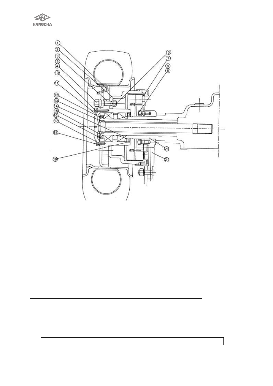
1. Wheel rim 

2. Brake drum 

3. Hub 

4. Nut 

5. Hub nut 

6. Nut 

7. Brake device 

8. Washer 

9. Bolt 

10. Differential side shaft nut 


11. Differential side shaft 

12. Bolt 

13. Oil seal 

14.Tapered roller bearing 

15. Adjusting nut 

16. Lock nut 

17. Pin 

18. Paper mat 

19. Oil seall 

20. Axle shell 

21.support sleeve   


3. Assembly and disassembly of driving axle 

WARNING 
Be careful when removal and installation driving axle as it is heavy. 

  Raise front end of forklift truck and support frame with wooden blocks. 

1)  Remove mast assembles. 
2)  Slightly  raise  axle  with  a  hoist  and  place  wooden  blacks  under  differential  gear 

carrier and transmission case. 

3)  After placing a pan under axle case, loose oil plug, drain oil from axle case. 
4)  Disconnect brake nuts from left and right cylinders.(see fig.3-1)。 

CAUTIONplug brake tube openings to prevent oil from flowing out.   


33 

5)  Disconnect brake cable at hand brake lever. 
6)  Remove front wheels. 
7)  Remove axle shaft. 
8)  Support driving axle with wire ropes and lifting device. 
9)  Remove bolts securing axle mounting bracket to frame.(see fig.3-2). 
10) Remove nuts securing axle case to differential gear carrier.(see fig.3-3). 
11) Remove driving axle assemble. 


Fig.3-1  


  Fig.3-2 


  Fig.3-3 

13)Remove brake drum,remove wheel hub. 
14) Remove axle mounting bracket and brake component from axle tube. 
15) Remove oil seal from axle tube. 
16)  To  install  driving  axle  assemble  in  the  reverse  order  of  removal.  Observe  the 
following: 
① When  installing  axle  mounting  bracket  and  brake  component,  apply  a  coat  of 

calcium grease to axle tube. 

② Apply 1/3~2/3 of volume of calcium grease to wheel hub,then install them on axle 

tube. 

③ Install oil seal with its part number facing to the inside of forklift truck. 
④ Attach seal tape (PVC, white)to drain plug then installed after cleaned it. 
⑤ Replenish axle case with gear oil. Tighten vent plug after clearing. 


GL-5 

85W/140 

Gear oil (L) 

2.8 

1t-1.8t hydro-transmission forklift 

1t-1.8t mechanical-transmission forklift 

3.2 

2t-3.5t 

hydro-transmission 

forklift 

except 

RW15A 

2t-3.5t mechanical-transmission forklift 

APIGL-5 

80W/90 

(L) 

3.2 

Only type N-RW15A、QN- RW11A lift truck 

Vent plug should clear instantly to prevent pressure inside of wheel hub from rising. 


4. Axle shaft and wheel hub 

Remove   

1) Raise the front end of forklift truck and support frame with wooden blocks. 
2) Remove front wheel and axle shaft. 
3) Remove  lock  nuts,  lock  washers,  snap  ring,  felt  ring,  adjusting  nut.  Use  special 

tools. 


34 

4) Remove brake drum(refer to Fig.3-4); 

If  brake  drum  is  difficult  to  remove:  a.  Remove  adjusting  hole  plug.  Then  with 
flat-blade  screwdriver  extend  adjusting  hole,  turn  adjusting  ratchet  wheel  by  10 
notches.  To  contract  brake  shoe  lining(refer  to  Fig.3-5).    b.  evenly  tapping  on 
brake drum with brass bar or wooden mallet. 


  Fig.3-4 


                        Fig.3-5 

5) Remove wheel hub, be careful not to drop bearing inner race. 
6) Remove oil seal and inner bearing as an assembly by evenly tapping on periphery 

of seal with a wooden mallet and brass bar. 

7) Remove  bearing  outer  race  from  wheel  hub  by  evenly  tapping  on  its  periphery 

with a wooden mallet. 
CAUTION:Be careful not to damage oil seal and outer race. 

Inspection 

Stepped wear or cracks on axle shaft splines 

replace 

Seized,  scratched,  noisy  or  rusted  bearing  or  improper 
rotation of rollers 

Replace   

Cracked or damage wheel hub 

Replace   

Damaged oil seal felt ring. 

replace 

    Installation 
    Install reverse order of removal. 
 

5. Bearing adjusting 

1) Lubricate on taper roller bearing. 
2) Tighten  roller  bearing  lock  nut  in  wheel  hub  until  wheel  hub  can  no  longer  be 

rotated with one hand. 

3) From that position, turn back lock nut approx. 60

0

4) Turn back wheel hub two or three rotations so that bearing settles down. 
5) Again  tighten  lock  nut until  it  can no  longer be  rotated  with  one  hand;  then turn 

back approx.60

0

6) Install snap ring and settles down felt ring, install lock washer so as to set its hole 

in the pin of snap ring. Screw lock nut. 

7) Turn  wheel  hub  back  and  forth  two  or  three  rotations  to  see  if  rotation  starting 

torque is within specifications. Rotation starting force:10N~29N (refer to Fig.3-6);


35 

8) Measure axial play of wheel hub to see if it is within specification. Axial play is less 

than 0.10mm (refer to Fig.3-7). 


Fig.3-6  


    Fig.3-7 


Content   ..  7  8  9  10   ..