1t-3.5t R Series Internal Combustion Counterbalanced Forklift Truck. Manual - part 8
 

  Index      Engines     HANGCHA 1t-3.5t R Series Internal Combustion Counterbalanced Forklift Truck - manual 2011 year


Search            


Content   ..  6  7  8  9   ..


1t-3.5t R Series Internal Combustion Counterbalanced Forklift Truck. Manual - part 8


28 


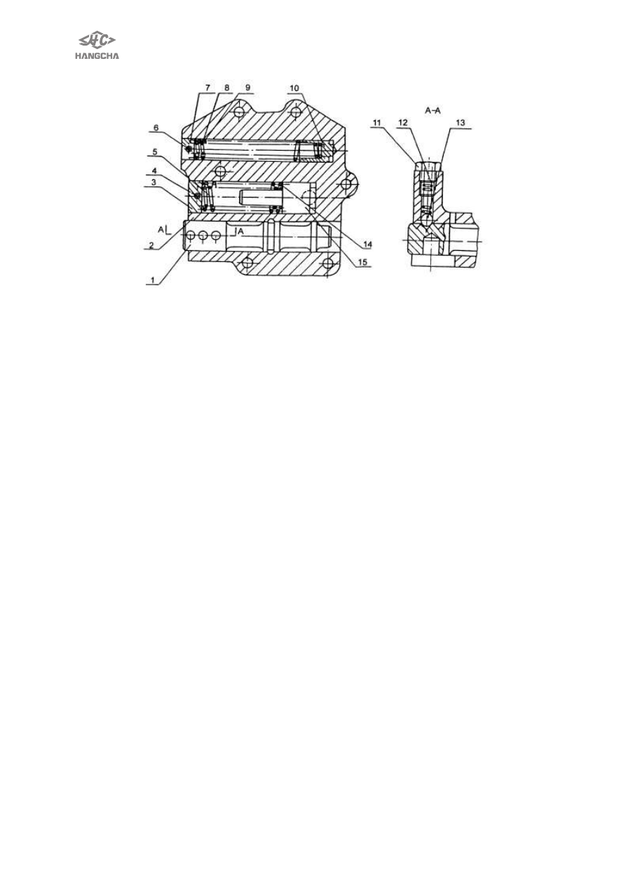
1 slide valve 

2 valve body 

3 plug 

4 flexible straight pin 4×40         5 spring 


6 flexible straight pin 4×35 

7 plug 

8 spring            9 spring                 10 piston 


11 drain plug 

12 spring 

13 steel ball  14 spring 

15 valve core 

Fig. 2-10 control valve 

Main pressure valve: also called fixed pressure valve, the oil pressure for controlling 
the hydrodynamic clutch is at 1.1MPa ~1.4MPa, assigns the oil to the relief valve, then 
to torque converter. 
Buffer  valve:  also  called  adjustment  valve,  between  the  inching  valve  and  the 
shift-control  valve.  When  the  control  valve  is  all  opened,  the  buffer  valve  begins  to 
work, for reducing the impact when the hydrodynamic clutch is connecting. 
Shift-control valve: assign the pressure oil to the forward or reverse clutch, so as to 
make the gear box change the gear ratio. 


29 

Structure of Automatic shift valveused for automatic shift type 


1t-1.8t 

2t-2.5t 

3t-3.5t 

Automatic shift 
hydraulic 
transmission 
gearbox 

YQXD18HA 

YQXD18E 

YQXD18H1 

YQXD18HB 

(the same of all 

except connect shell) 

YQXD25A 
YQXD25A 

YQXD25H 

YQXD25H1 

YQXD25G1(the 

same of all except 

connect shell) 

YQXD30A 
YQXD30A 

YQXD30H 

YQXD30H1 

YQXD30G1(the 

same of all except 

connect shell) 

similarities and 
differences 

Electrical shift 

compare with YQX18 

Electrical shift 

compare with 

YQX25 

Electrical shift 

compare with YQX30 

characteristic 

Automatic shift valve: Electrical shift 


1.Shell body cover 

2.interior hex bolt of taper pipe 

3.pin 

4.paper gasket 

5.tube tie-in 

6. electromagnetic shift valve 

7.pin 

8.small piston 

9.spring 

10.combine seal 

11. relief valve cover 

12.piston 

13.small spring of fixed pressure valve 

14.big spring of fixed pressure valve 

15. elasticity columnar pin 

16. round plug of fixed pressure valve 

17. round plug of control valve 

18. big spring of control valve 

19. small spring of control valve 

20.reel 

21.bolt 

22.shell body 

23.gasket 

24. interior hex bolt of taper pipe 


30 

5. Notice about installation and usage 

5.1 Before installation, first clean oil of oil seal on surface of hydraulic gearbox, to 

avoid leaking when working, no disassemble freely hydraulic gearbox.   

5.2 To avoid affecting precision of installation and usage must prevent every 

installation surfaces, torque converter and out gear knocking. 

5.3 Guarantee no more than 0.15mm runout for installation hole of engine flywheel, no 

more than 0.1mm for flywheel end surface, no more than 0.2mm for installation 
end surface of flywheel,    no more than or equal to Ф0.1mm for location position of 
2 location pins on installation surface. 

5.4 Truck control mechanism must guarantee correct stroke of inching valve lever, 

and secure location. Inching valve lever can return its initial location when operator 
loosens pedal. Inching valve characteristic graph,see Fig.2, inching valve lever 
can move    together with brake pedal, must guarantee cut off the oil to clutch 
before braking ,and    the stroke of inching valve lever is equal to or more than 
14mm(less than 22mm) ,when shifting, close inching valve first ,and then shift. 

5.5 When hoisting, keep level, ensure gearbox and reduction gearbox calm, and avoid 

torque converter sliding out. 

5.6 Prohibit changing oil system of the gearbox.    To ensure gearbox work regularly, 

lubricate well, the circular oil of gearbox can not be used for other purpose, and the 
oil should accord with required trademark. 

5.7 Keep work oil clean and no other impurity, replace new oil after 50 hours usage for 

new truck, and after every 1000 hours,or reuse after long depositing.   

5.8 Fill in work oil, run at neutral shift for5 minutes, then check oil height, and the 

height should be within the specified range.     

5.9 New hydraulic gearbox should breaking in 50 hours after it is installed,and the load 

is no more than 70% in breaking in process, note oil temperature ,oil pressure and 
bolts loosen or not usually, replace new oil after breaking in . 


6. Cause and solutions 

Faults 

Causes and remedy 

Efficiency deceased 

and oil temperature 

too high 

1.  Friction  discs  seized  or  worn  out.  Check  friction  discs  for 

agglutination, uneven contact or warp. 

2.  Insufficient oil for torque converter. Check oil pump for worn part 

and check the oil level. 

3.  Bearing damaged. Replace the bearing. 
4.  Check lubricant line for blocking. 
5.  One-way clutch of torque converter seizure. Replace the torque 

converter. 

Oil leakage 

1.  Sealing washer wear. Replace the worn sealing washer. 
2.  Ageing or damage of rubber parts. Replace the parts. 
3.  Parts damaged and cracks. Replace. 

Clutch pressure low 

and excessive 

vibration 

1.  Oil level too low. Check oil level and refill oil to proper level. 
2.  Sealing ring on clutch shaft and piston worn out or joint jammed 

when  assembling.  Replace  sealing  ring  and  pay  attention  to 
joint when assembling. 

3.  Oil pump worn. Replace oil pump. 
4.  Oil strainer blocked. Clean or replace.   
5.  Check if the inching valve spool returns. 


31 

Ⅲ. Driving axle 


1. Date 

Driving axle type 

Full floating, axle and truck body direct 

install, front wheel driving 

Tire pressure 

(7±0.2)×10

5

Pa 

Wheel hub rotation starting torque at hub blot           

10 N~29 N 

Axial play of wheel bearing    mm 

less    0.08 


2. Trouble diagnoses and corrections 


condition 

Probable cause 

Corrective action 

Abnormal noises   

·

loose  driving  axle  and  body  connecting 

blots. 

·

loose wheel nut 

·

worn or damaged wheel hub bearing. 

·

wheel hub bearing not properly adjusted. 

·

worn axle shaft spliner. 

·

insufficient lubrication 

Tighten. 

Tighten. 

Replace. 

Adjust. 

Replace. 

Lubricate. 

Unstable driving 

·

loose wheel nut. 

·

deformed wheel. 

·

worn or damaged wheel hub bearing. 

·

loose  driving  axle  and  body  connecting 

blots. 

·

wheel hub bearing not properly adjusted. 

·

improper tire pressure. 

Tighten. 

Replace. 

Replace. 

Tighten. 

Adjust. 

Adjust. 

Oil leakage 

·

worn or damaged axle shaft oil seal. 

·

final drive improperly installed. 

·

loose drain plug. 

Replace   

Replace gasket. 

Tighten. 


Content   ..  6  7  8  9   ..