1t-3.5t R Series Internal Combustion Counterbalanced Forklift Truck. Manual - part 7
 

  Index      Engines     HANGCHA 1t-3.5t R Series Internal Combustion Counterbalanced Forklift Truck - manual 2011 year


Search            


Content   ..  5  6  7  8   ..


1t-3.5t R Series Internal Combustion Counterbalanced Forklift Truck. Manual - part 7


24 

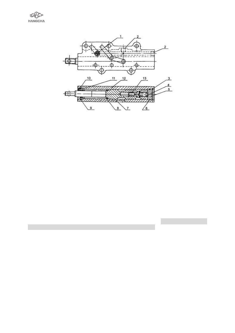
4.4 Inching valve 


1 threaded plug 

2 threaded plug 

3 elastic snap for hole    4 spring 

5plug6 o-ring 

7 inching valve lever    8 spring 

9 elastic snap for hole 

10 oil seal11 block 

12 inching valve body 

13 inching-slide valve 


Fig. 2-6 inching valve 


Inching valve is installed outside the gear box. Inching valve lever 7 is connected 

to the inching pedal lever, when put foot down, inching valve lever moves to the right 
side, so it reduces the oil pressure for clutch, make the truck inching moving by slide 
the clutch disc. 
 
4.5 Hydrodynamic clutch (Refer to fig.2-7) 
4.5.1 Summarizer   

Wet  and  multi-blade  hydrodynamic  clutch  is  installed  on  the  input  shaft  of  the 

hydrodynamic  gear  box,  assign  the  pressure  oil  to  the  forward  or  reverse  clutch 
through the control valve, so the truck can travel in forward or reverse direction. All the 
gears  in  the  gear  box  is  the  mesh-always  gear.  Every  clutch  of  the  YQX30  model 
clutch assembly consists of 4 interphase-installed septa 18  、4 disc 19 and a piston 2. 
Every clutch of the YQX18 model clutch assembly consists of 3 interphase-installed 
septa  18、3  disc  19  and  a  papilionaceous  plate,  a  piston  2  (YQX18  model  clutch 
assembly is different from the YQX25/30 clutch only for this) . The ring 17 installed in 
the  outer  rounder  of  the  piston,  o-ring  3  in  the  input  shaft,  for  ensuring  be  airproof 
when the piston is working. When at idle motion, the piston does not work, the septa 
separates from the disc. When change over the gear ration, the pressure oil makes 
the piston、septa and disc impacted, transmit the power from the torque converter to 
the forward-gear-ratio gear or the reverse gear 6 depending on friction. 


25 


1 plate 

2 piston 

3 O-ring 

4 forward-gear -ratio gear 

    5 

backhaul spring  6 reverse gear 

7 bearing 

8 ring (A) 

9 input shaft assembly 

10 restrain ring (A) 

11 needle bearing 12 restrain ring(A) 13 elastic snap ring for 

shaft                    14 spring seat 

15 steel ball 

16 plug 

17 ring (A) 

18 

septa                    19 disc 

20 clip ring


Fig 2-7    hydrodynamic power clutch 

 
4.5.2 Disassembly, assembly sequence 

①  Take off the bearings 7 on the left and right sides; 
②  Separately take off the forward-gear-ratio gear 4、reverse-gear-ratio gear 6、

disc 19、septa 18; 

③  Separately compress the spring 5, take off the snap ring 13, remove the piston 

2 and spring 5. 
          Assembling procedures is contrary to those of disassembly. 
NOTE
·  Flush the piston cavity of the input shaft assembly、oil route, clean the other parts 
except the disc. 
·  Replace the ring(A)、(B) if it is damaged. 
·  Replace the snap ring. 
·  Replace the disc if it is overly abraded or bend.   
·  Restrained ring(A)、(B) should face to gears. 
·  After assembled, rotate the gears, it should be freely rather than locked. 


26 

4.6 Reduction transmission and differentials 


1. Gear ring 

2. Bolt 

3. Bearing holder 

4. Ball bearing 

5. Thrust washer 

6. Taper roller bearing 

7. Bearing cover 

8. gasket 

9.“O”ring 

10. Output shaft 

11. Pinion 

12. Helical bevel gear 

13.Column pin 

14. Gear shaftⅠ 

15. Gear shaftⅡ 

16. Semi-axle gear 

17. Gasket 

18. Planetary gear 


Fig.2-8 Reduction gear ,Differential 

4.6.1 Reduction gear (as shown in Fig.2-8) 

Reduction gear is in the front of transmission, which reduces the speed of output 

shaft  of  transmission  and  increase  the  torque  from  output  shaft  to  differential; 
reduction gear is mainly composed by a small helical bevel gear on the output shaft,
a big helical bevel gear and a small gear shaft,the big helical bevel gear is fixed in a 
small gear shaft through spline, two ends of small gear shaft are all holden by taper 
roller bearing and adjusted gap by shim. 
 

4.6.2 Differential(as shown in Fig.2-8  ) 

Differential is installed on front hull by bearing holder through ball bearing on both 

ends, which front end connect with axle carriage. Differential carriage is divided into 
left and right half, which is composed of two semi-axle gears and four planetary gears. 
Thrust      ring  is  put  between  differential  carriage  and  gears  in  order  to  have  a 
clearance between    pairs of gears. Planetary gear is holden by gear shaft I,II. Gear 
shaft I is secured to differential carriage by columnar pin, and gear loop 1 is secured to 
differential carriage byream bolt . 

The  power  from  transmission  transmits  to  wheel  through  semi-axle  gear  and 

semi-axle when it is reduced to come into differential driving by differential. 
 

4.6.3. Remove differential(as shown in Fig.2-8) 

① Take down bolts securing bearing seat of differential. 
② Take down the section of differential from transmission. 
③ Loose and take down bolt 2 and column 13, detach differential left hull from right 


27 

hull. 

④ Take respectively down thrust washer 5, gear 14, planetary gear18, semi-axle gear 

16, washer 17, gear shaft 15 etc. 

      Caution:Be sure to lay adjust shim dividually and not to be mixed up.             

4.6.4 Remove reduction gear(as shown in Fig.2-8) 

①  Loose and take down the fixing bolts of two ends of bearing cover 7. 
②  Gently tap the front of pinion 11 near helical bevel gear. 
③  Take down bearing 6, pinion 11, helical bevel gear 12. 

  Caution:Be sure location of adjust shim 8, and adjust shim of both ends should be lay dividually 

and not be mixed up. 


4.6.5 Assembly 

Assemble in the reverse order of removal, but be sure: 

a. Prevent each fixing connecting face and gear tooth surface from knocking to be 

damaged. 

b. Apply  working  faces  of  parts  such  as  bearing,  gear,  seal  ring  and  relatively 

movement parts with a little gear oil to prevent them from coming into being instant 
dry friction while early running. 

c. Each part should be assembled correctly. 
d. Each part should be running smoothly to prevent it from getting stuck. 
e. Be sure to tighten firmly each joint bolt. 
 
4.7. Case and control valve 

Case and control valve is installed inside the shell of gear box. It consists shell body case 1 

and control valve 3. There are a gearlever shaft 2 and an 

overflow valve 4 installed on the shell 

body case, 

keep the oil pressure for torque converter between 0.5MPa ~0.7MPa, prevent the air 

erode. 


1.shell body            2. gearlever shaft          3.assembly of control valve          4.overflow valve 

Fig. 2-9 case and control valve 

The assembly of control valve consists Main pressure valve 10、Buffer valve 15、

shift-control valve 1etc. See Fig. 2-10. 


Content   ..  5  6  7  8   ..