1t-3.5t R Series Internal Combustion Counterbalanced Forklift Truck. Manual - part 5
 

  Index      Engines     HANGCHA 1t-3.5t R Series Internal Combustion Counterbalanced Forklift Truck - manual 2011 year


Search            


Content   ..  3  4  5  6   ..


1t-3.5t R Series Internal Combustion Counterbalanced Forklift Truck. Manual - part 5


16 

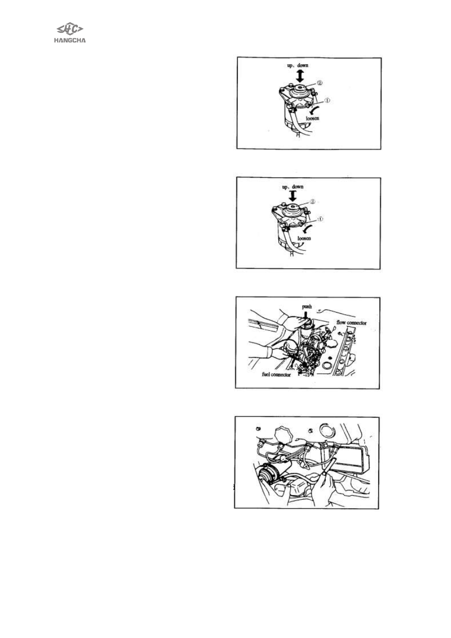
With air vent screw 
Method A: 
1.  Loosen the air vent screw   
2.  Move  the  priming  pump  up  and 

down  until  no  further  air  bleed  comes 
out of the air vent screw. 

3.  Tighten the air vent screw. 
4.  Move  the  priming  pump    up  and 

down  until  there  is  suddenly  more 
resistance in the movement. 

Method B: 
1.  Loosen the air vent screw. 
2.  Move  the  priming  pump    up  and 

down  until  no  further  air  bleed  comes 
out of the air vent screw. 

3.  Tighten the air vent screw. 
4.  Loosen  injection  pump  bleeder 

screw/or  disconnect  return  hose  and 
priming. 

5.  Make  sure  that  fuel  overflows  at 

bleeder  screw/tube  end,  then  tighten 
it/connect hose. 

Checking Priming Pump 
Before  checking  priming  pump,  make 

sure that fuel filter is filled with fuel. 

1. Disconnect  fuel  return  hose.  Place  a 

suitable container beneath hose end. 

2. Pump  priming  pump  and  check  that 

the fuel .Overflows from the hose end. If 
not, replace priming pump. 


17 


Ⅱ. Hydrodynamic transmission,torque converter 


Hydrodynamic 

transmission,torque 

converter 

for 

CPCD20/25/30/35N-RW15A,CPQD20/25/30/35N-RW22A  see 《 import  NISSAN   
MOTOR CO.,LTD SERVICE MANUAL FOR THREE MAIN COMPONENT  
》. 

CPCD20/25/30/35N-RW1B, 

CPCD20/25/30/35N-RW6B, 

CPCD20/25/30/35N-RW9B, 

CPCD20/25/30/35N-RW13B

、 

CPQD20/25/30/35N-RW22B, 

CPCD20/25/30/35N-RW33B 

see 

import 

OKAMURA(Japan)    MOTOR CO.,LTD SERVICE MANUAL FOR TRANSMISSION  

CPCD20/25/30/35N-RWE33M see《2~3.5 TON    TRANSMISSION AND DRIVE 

AXLE》. 

The others see as follows: 


1. Summary 

YQX18, YQX25, YQX30 model hydrodynamic transmission gear box consists of 

hydrodynamic torque converter and power shift which has two shifts(forward/reverse) 
transmission box.( Fig 2-3).   

It has virtues as follows: 

① Hydrodynamic transmission gear-box has automatic adaptability for hydrodynamic 

transmission output, it can change it’s output torque and rotation speed according 
to the external load; 

② It can absorb and remove the impact liberation that the engine and external load 

brings to the transmission system; 

③ Inching valve, cushion valvecan make the truck to move a little when the engine in 

either  low  speed  or  high  speed,  make  the  operation  easy、convenient,  steady 
starting, reduce the labor intension of operators.   


18 

2. Data 

Models 

YQX18 

YQX25 

YQX30 

Hydrodynamic 
torque 
converter 

Type 

Single stage、Two-phrase、Three-element 

Model 

YJH265 

Max.  torque  converter 
ratio      K

0


Diameter  of  circulating 
chamber 
D(mm) 

265 

Max  efficiency           

η

max 

0.79 

Transmission 
ratio   

Forwards 

19.2065 

15.3652 

17.4972 

Backwards   

19.2065 

15.3652 

17.4972 

Hydrodynamic 
power 
clutch 

Clutch disc diameter(out)× 
diameter(in)×  thickness 

125mm×  81mm×  2.7mm 

Clutch disc area 

71cm

2


Adjusted pressure 

1.1 MPa ~1.4MPa 

Reduction 
transmission 

Reduction gear 

Helical bevel gear 

Reduction ratio 

2.5 

2.1 

Differential 

Reduction gear 

Straight bevel gear 

Differential gear 

Straight bevel gear 

Reduction ratio 

5.7 

5.7 

6.182 

Mass (kg) 

160 

165 

185 

Total gear ratio (F/R)                    i 

19.2065 

15.3652 

17.4972 

Oil capability (L) 

Using oil type 

6# Hydrodynamic power transmission oil 

overall dimension(length×width×height)


mm×  mm×  mm 

740×470×450 

830×470×450 


19 

3. Working principles 

3.1 Hydrodynamic transmission gear-box power transmit 
      Gear-box  transmission  sketch,  see fig.  2-1,  torque  converter  is  driven  by  engine 
through a elastic plate 1, it rotates the impeller wheel 4, in this way, the fluid flows at 
high speed into the turbine wheel 2 and rotates the turbine wheel. Stator wheel make 
the torque converter effective, through turbine shaft 5, it transmit the torque to input 
shaft assembly 11. When at forward gear ratio, reverse clutch at idle motion, transmit 
order is that 11→7→20→19→12→13, drives the differential 15 to output the torque. 
When at reverse gear ration, onward clutch at idle motion, transmit order is that 11→
10→18→21→20→19→17→12→13,  drives  the  differential  15  to  output  the  torque. 
Onward  and  reverse  clutch  are  controlled  by  shift  control  valve.  Oil  pump  6  is 
inner-mesh gear pump, it is driven by engine through impeller wheel, oil pump supply 
the oil for the system, after hydrodynamic torque converter works, the oil flows into the 
radiator , then into gear-box-lubrication clutch disc、bearings and gears. 


Fig. 2-2 YQX18/25/30 model hydrodynamic transmission gear box sketch 


1 elastic plate 

2 turbine wheel 

3 stator wheel 

4 impeller wheel 

5 turbine shaft 

6 oil pump 

7 gear(forward gear ratio) 

8 clutch disc 

9 septa 

10 gear(reverse gear ratio) 

11 input shaft assembly 

12 gear shaft 

13 gear ring 

14 half-axle gear 

15 differential assembly 

16 planet gear 

17 helical bevel gear 

18 idler shaft 

19 output shaft 

20 output gear 

21 idler wheel 


Content   ..  3  4  5  6   ..