1t-3.5t R Series Internal Combustion Counterbalanced Forklift Truck. Manual - part 6
20
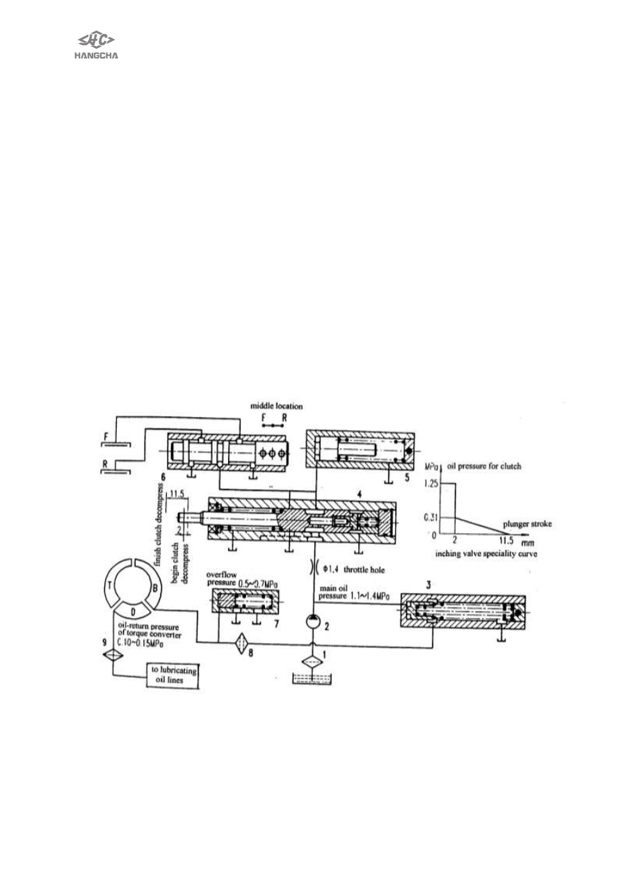
3.2 hydraulic oil pipe system (see fig 2-2)
After the engine starts, oil-supply pump absorbs the oil from the tank (on the bottom
of gear-box) through the oil strainer, the oil flows into the control valve, then separate
itself into two parts, the one part for hydrodynamic power clutch, the others for the
torque converter.
The oil for hydrodynamic power clutch flows into main-pressure valve (pressure at
1.1MPa ~1.4MPa), then separate itself into two parts, the one part into inching valve
and shift-control valve, the others into
overflow valve(pressure at 0.5MPa ~0.7MPa) and supply for the blade wheel of torque
converter. The oil, from the torque converter, is cooled when passing through the
radiator, then it lubricates the hydrodynamic power clutch, at last, the oil comes back
into the tank.
When at idle motion, the oil route, from the shift-control valve to clutch, is closed.
At this time , the main-pressure valve is opened, the oil absolutely flows into the
torque converter through the overflow valve, when the shift control valve is at the
position of forward gear ratio or the reverse gear ratio, the oil route, from the slide
valve to onward clutch or the reverse clutch, is connected to make the clutch do its
work respectively; when the one clutch works, the other clutch’s disc and septa are
separated, the cooling oil lubricate it and take the heat away; when the inching pedal
works through operating the inching valve, some or a majority of oil, from the clutch,
comes back into the tank through the inching valve lever, at this time, the oil circle of
the torque converter is the same as at the idle motion.
1 oil strainer
2 oil pump
3 main-adjustment-pressure valve
4 inching valve
5 buffer valve
6 shift-control valve
7 relief valve
8 oil strainer
9 cooling device
Fig.2-2 oil route for YQX18/25/30 model hydrodynamic power transmission gear box