Perkins 402D, 403D, 404D Industrial Engine. Manual - part 18
 

  Index      Engines     Perkins 402D, 403D, 404D Industrial Engine - service manual


Search            


Content   ..  16  17  18  19   ..


Perkins 402D, 403D, 404D Industrial Engine. Manual - part 18


SEBU8311-01

71

Maintenance Section

Engine Air Precleaner - Check/Clean

Some engines are equipped with a differential gauge

for inlet air pressure. The differential gauge for inlet

air pressure displays the difference in the pressure

that is measured before the air cleaner element and

the pressure that is measured after the air cleaner

element. As the air cleaner element becomes dirty,

the pressure differential rises. If your engine is

equipped with a different type of service indicator,

follow the OEM recommendations in order to service

the air cleaner service indicator.

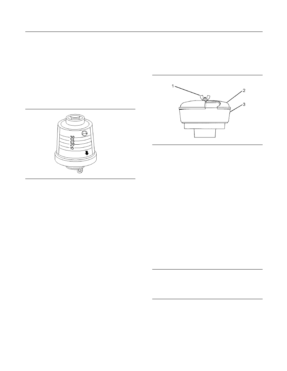
The service indicator may be mounted on the air

cleaner element or in a remote location.

g00103777

Illustration 42

Typical service indicator

Observe the service indicator. The air cleaner

element should be cleaned or the air cleaner element

should be replaced when one of the following

conditions occur:

The yellow diaphragm enters the red zone.

The red piston locks in the visible position.

Test the Service Indicator

Service indicators are important instruments.

Check for ease of resetting. The service indicator

should reset in less than three pushes.

Check the movement of the yellow core when

the engine is accelerated to the engine rated

speed. The yellow core should latch at the greatest

vacuum that is attained.

If the service indicator does not reset easily, or if the

yellow core does not latch at the greatest vacuum,

the service indicator should be replaced. If the new

service indicator will not reset, the hole for the service

indicator may be restricted.

The service indicator may need to be replaced

frequently in environments that are severely dusty.

i02927289

Engine Air Precleaner -

Check/Clean


g01453058

Illustration 43
Typical engine air precleaner
(1) Wing nut
(2) Cover
(3) Body

Remove wing nut (1) and cover (2). Check for an

accumulation of dirt and debris in body (3). Clean the

body, if necessary.

After cleaning the precleaner, install cover (2) and

wing nut (1).

Note: When the engine is operated in dusty

applications, more frequent cleaning is required.

i02657627

Engine Crankcase Breather -

Replace


NOTICE

Keep all parts clean from contaminants.

Contaminants may cause rapid wear and shortened

component life.

72

SEBU8311-01

Maintenance Section

Engine Mounts - Inspect

g01335247

Illustration 44

Typical example
(1) Screws for the breather cover
(2) Breather cover
(3) Spring
(4) Diaphragm and plate
(5) Spacer for turbocharged engines only
(6) Joint for turbocharged engines only
(7) Cavity
(8) Vent hole

1. Loosen the screws (1) and remove the breather

cover (2) from the valve mechanism cover.

2. Remove the spring (3). Remove the diaphragm

and plate (4).

3. For turbocharged engines, remove the spacer (5)

and the joint (6).

4. Clean the vent hole (8) and the cavity (7) in the

valve mechanism cover.

NOTICE

Make sure that the components of the breather as-

sembly are installed correctly. Engine damage may

occur if the breather assembly is not working correctly.

5. For turbocharged engines, install a new joint (6)

and the spacer (5).

6. Install a new diaphragm and plate (4) for the

breather assembly into the cavity (7) of the

valve mechanism cover or the spacer (5) for

turbocharged engines.

7. Install a new spring (3).

8. Install the breather cover (2) and the four screws

(1). Tighten the screws.

i02323089

Engine Mounts - Inspect


Note: The engine mounts may not have been

supplied by Perkins. Refer to the OEM information

for further information on the engine mounts and the

correct bolt torque.

Inspect the engine mounts for deterioration and for

correct bolt torque. Engine vibration can be caused

by the following conditions:

Incorrect mounting of the engine

Deterioration of the engine mounts

Loose engine mounts

Any engine mount that shows deterioration should

be replaced. Refer to the OEM information for the

recommended torques.

i02153660

Engine Oil Level - Check


Hot oil and hot components can cause personal

injury. Do not allow hot oil or hot components to

contact the skin.

g00110310

Illustration 45
(Y) “ADD” mark. (X) “FULL” mark.

SEBU8311-01

73

Maintenance Section

Engine Oil and Filter - Change

NOTICE

Perform this maintenance with the engine stopped.

1. Maintain the oil level between “ADD” mark (Y) and

“FULL” mark (X) on oil level gauge (1). Do not fill

the crankcase above “FULL” mark (X).

NOTICE

Operating your engine when the oil level is above the

“FULL” mark could cause your crankshaft to dip into

the oil. The air bubbles created from the crankshaft

dipping into the oil reduces the oil’s lubricating char-

acteristics and could result in the loss of power.

2. Remove the oil filler cap and add oil, if necessary.

Clean the oil filler cap. Install the oil filler cap.

i02610655

Engine Oil and Filter - Change


Hot oil and hot components can cause personal

injury. Do not allow hot oil or hot components to

contact the skin.

NOTICE

Care must be taken to ensure that fluids are contained

during performance of inspection, maintenance, test-

ing, adjusting and repair of the product. Be prepared to

collect the fluid with suitable containers before open-

ing any compartment or disassembling any compo-

nent containing fluids.

Dispose of all fluids according to local regulations and

mandates.

NOTICE

Keep all parts clean from contaminants.

Contaminants may cause rapid wear and shortened

component life.

Do not drain the oil when the engine is cold. As the oil

cools, suspended waste particles settle on the bottom

of the oil pan. The waste particles are not removed

with the draining cold oil. Drain the crankcase with

the engine stopped. Drain the crankcase with the

oil warm. This draining method allows the waste

particles that are suspended in the oil to be drained

correctly.

Failure to follow this recommended procedure will

cause the waste particles to be recirculated through

the engine lubrication system with the new oil.

Drain the Engine Oil

After the engine has been run at the normal operating

temperature, stop the engine. Use one of the

following methods to drain the engine crankcase oil:

If the engine is equipped with a drain valve, turn the

drain valve knob counterclockwise in order to drain

the oil. After the oil has drained, turn the drain valve

knob clockwise in order to close the drain valve.

If the engine is not equipped with a drain valve,

remove the oil drain plug in order to allow the oil to

drain. After the oil has drained, the oil drain plug

should be cleaned and installed.

Replace the Oil Filter

NOTICE

Perkins oil filters are built to Perkins specifications.

Use of an oil filter not recommended by Perkins could

result in severe engine damage to the engine bear-

ings, crankshaft, etc., as a result of the larger waste

particles from unfiltered oil entering the engine lubri-

cating system. Only use oil filters recommended by

Perkins.

1. Remove the oil filter with a suitable tool.

Note: The following actions can be carried out as

part of the preventive maintenance program.

2. Cut the oil filter open with a suitable tool. Break

apart the pleats and inspect the oil filter for metal

debris. An excessive amount of metal debris in

the oil filter may indicate early wear or a pending

failure.

Use a magnet to differentiate between the ferrous

metals and the nonferrous metals that are found in

the oil filter element. Ferrous metals may indicate

wear on the steel and cast iron parts of the engine.

Nonferrous metals may indicate wear on the

aluminum parts, brass parts or bronze parts of

the engine. Parts that may be affected include

the following items: main bearings, rod bearings,

turbocharger bearings, and cylinder heads.

Due to normal wear and friction, it is not

uncommon to find small amounts of debris in

the oil filter. Consult your Perkins dealer or your

Perkins distributor in order to arrange for a further

analysis if an excessive amount of debris is found

in the oil filter.

74

SEBU8311-01

Maintenance Section

Engine Valve Lash - Inspect/Adjust

g01334593

Illustration 46
(1) Oil cooler
(2) Adapter
(3) Oil filter

Note: The oil cooler (1) and the adapter (2) are

installed on engines that have a turbocharger.

3. Clean the sealing surface of the cylinder block or

the oil cooler (1).

4. Apply clean engine oil to the new oil filter seal (3).

NOTICE

Do not fill the oil filters with oil before installing them.

This oil would not be filtered and could be contaminat-

ed. Contaminated oil can cause accelerated wear to

engine components.

5. Install the oil filter. Tighten the oil filter by hand. Do

not overtighten the oil filter.

Fill the Engine Crankcase

1. Remove the oil filler cap. Refer to the Operation

and Maintenance Manual for more information on

lubricant specifications. Fill the crankcase with the

correct amount of oil. Refer to the Operation and

Maintenance Manual for more information on refill

capacities.

NOTICE

If equipped with an auxiliary oil filter system or a re-

mote oil filter system, follow the OEM or filter manu-

facturer’s recommendations. Under filling or overfilling

the crankcase with oil can cause engine damage.

NOTICE

To prevent crankshaft bearing damage, crank the en-

gine with the fuel OFF. This will fill the oil filters before

starting the engine. Do not crank the engine for more

than 30 seconds.

2. Start the engine and run the engine at “LOW

IDLE” for two minutes. Perform this procedure in

order to ensure that the lubrication system has

oil and that the oil filters are filled. Inspect the oil

filter for oil leaks.

3. Stop the engine and allow the oil to drain back to

the sump for a minimum of ten minutes.

g00986928

Illustration 47

Typical example

4. Remove the oil level gauge in order to check the

oil level. Maintain the oil level between the “MIN”

and “MAX” marks on the oil level gauge.

i02676023

Engine Valve Lash -

Inspect/Adjust


This maintenance is recommended by Perkins as

part of a lubrication and preventive maintenance

schedule in order to help provide maximum engine

life. The maintenance for the valve lash is important

in order to keep the engine compliant.

NOTICE

Only qualified service personel should perform this

maintenance. Refer to the Service Manual or your au-

thorized Perkins dealer or your Perkins distributor for

the complete valve lash adjustment procedure.

Operation of Perkins engines with incorrect valve lash

can reduce engine efficiency, and also reduce engine

component life.


Content   ..  16  17  18  19   ..