Diesel engines D-260.1S3А, D-260.2S3А, D-260.4S3А. Manual - part 40
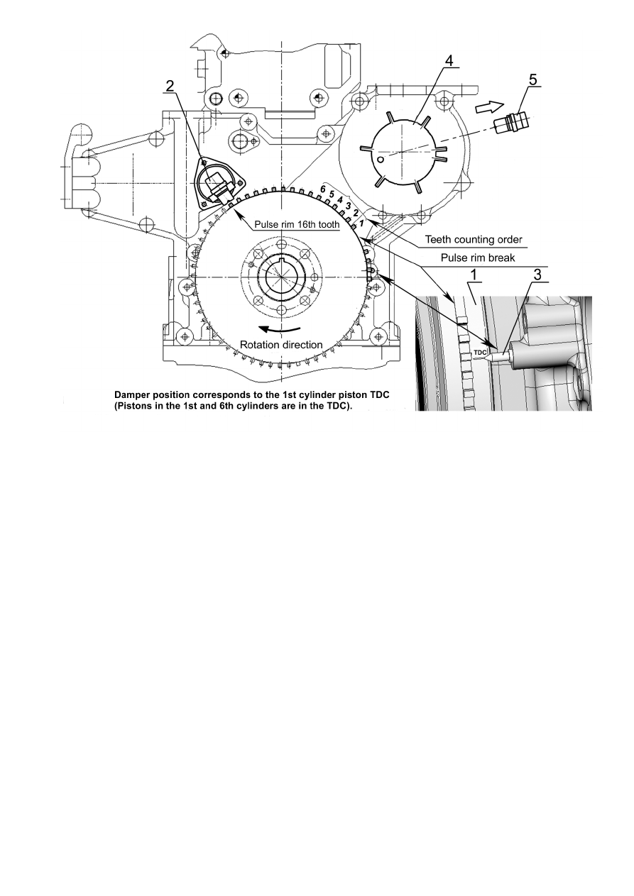
1 – torsional vibration damper housing ; 2 – crankshaft speed sensor; 3 – mounting pin; 4 – fuel priming
pump drive gear with pulse rim; 5 – HPFIP camshaft speed sensor.
Fig. 2 – Placing the 1
st
cylinder piston to TDC
Place the
1st cylinder piston behind ≈ 60° of the crankshaft turn angle before TDC. To do
that:
- rotate the crankshaft clockwise, using the crankshaft pulley mounting bolt approximate-
ly by two turns, with that, at the second turn, rotate the crankshaft till the coincidence of
mounting pin 3 and “C” mark on damper 1 housing (Fig. 3);
Thus, the pulse “crown” teeth will be positioned so that the axis of sensor 2 will lie along
the 6
th
tooth of the pul rim “crown” (counting against the clock from the pulse rim
“crown” breaking segment).