Diesel engines D-260.1S3А, D-260.2S3А, D-260.4S3А. Manual - part 35
 

  Index      Engines     Diesel engines D-260.1S3А, D-260.2S3А, D-260.4S3А - service manual


Search            


Content   ..  33  34  35  36   ..


Diesel engines D-260.1S3А, D-260.2S3А, D-260.4S3А. Manual - part 35


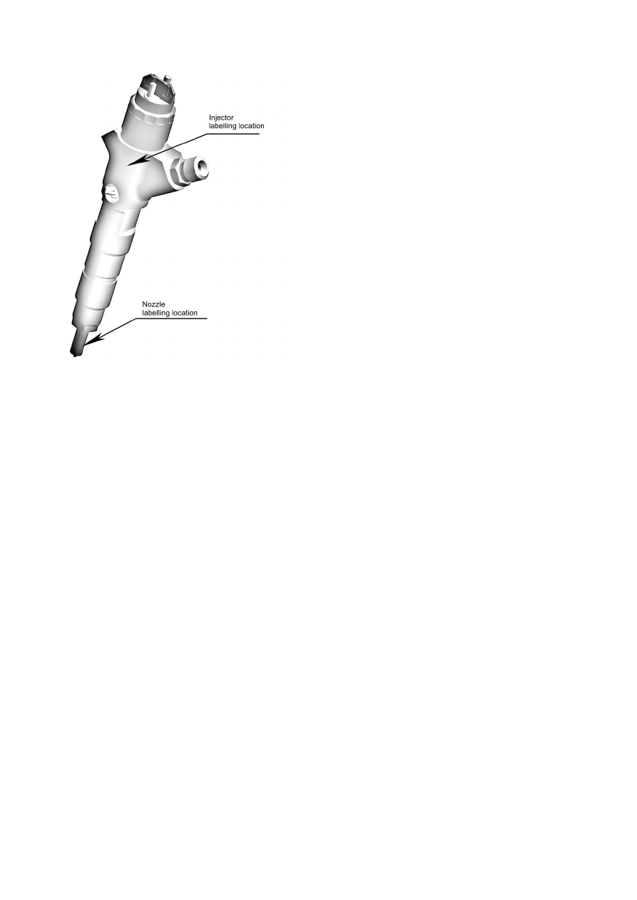
Fig. 26 - Injector 
 
3.2.17  Alternator maintenance 
 
There is no need in the alternator special maintenance during the engine operation. Sea-
sonal alternator voltage “winter-summer” adjustment is done with a “winter-summer” 
adjustment screw (if available) located on the alternator rear wall.  
Diesel engines may be equipped with alternators with automatic “winter-summer” voltage 
adjustment. With that, the “winter-summer” adjustment screw is not there.  
Make sure the alternator mounting and that of the alternator wiring are reliable and keep 
the alternator outer surface and terminals clean.  
The alternator operability is checked with a voltage meter or with a control lamp and an 
ammeter located on a vehicle dashboard. With the alternator operable, a control lamp 
lights up at the mass switch-on before the engine start. After the engine start and at the 
engine running at the middle speed the control lamp fades away, the voltage metter arrow 
must stay in the green zone and the ammeter must show some charge current the value of 
which goes down as the battery charge is restored.  
 
3.2.18  Checking the belts tension 
 
Checking the belts tension is done after every 125 engine operation hours. 
The alternator belt tension is considered normal, if its deflection on the branch “crank-
shaft pulley-alternator pulley” stays within 13 mm to 18 mm when pressed with a force of  
40±2 N. To adjust the belt tension, loosen the alternator mounting. Adjust the belt tension 
turning the alternator housing. Tighten the alternator plate mounting bolt and the alterna-
tor mounting bolt nuts. 


The water pump drive belt (D-260.1S3

А, D-260.2S3А, D-260.4S3А) deflection must stay 

within 9…18 mm when the branch “water pump pulley-crankshaft pulley” is pressed on 
with the force of 39,2±2,0 N. 

3.2.19  Checking the starter motor condition 
 
Checking the starter motor condition is done after every 1 000 engine operation hours in 
the following manner: 
- check the mounting bolts tightening, if necessary, tighten them;   
- clean the ends of the wires leading to the starter motor terminals and the accumulator 
battery and tighten their mountings.  
The preventive examination and servicing must be done after every 2 000 engine operation 
hours.  
Remove the cover from the collector side and check the brush-collector unit condition. The 
coolector working surface must be smooth and should not contain any stains of considera-
ble burn. If the collector is dirty or has stains of considerable burn, wipe it with a clean 
napkin soaked in gasoline. If it is impossible to remove dirt or stains of burn by wiping, 
clean the collector with a piece of small grained sand paper. With stains of considerable 
burn not going off with wiping use a machine tool for cleaning the collector.  
The brushes must freely travel inside the holders and be firmly pressed to the collector. In 
case of the brushes extreme wear as well as with considerable cleavage replace them by 
new ones. Blow the brush-collector unit and the cover with compressed air on the collec-
tor side.  
Check the starter notor relay contact system condition. With considerable burn, clean the 
contact bolts and the contact plate with a piece of sand paper or a file removing the une-
venness caused by burn, but not damaging the copper bolts contact surfaces flatness. With 
the contact plate and bolts extreme wear, turn the contact plate over and the contact bolts 
for 180°. Check smoothness of the drive travel along the armature shaft. At the relay 
switch-on/ switch-off the drive must travel along the armature shaft slits without jamming. 
Remove dirty thick grease from the inner surfaces of the drive guiding bush (slit and 
smooth) brought from the crankcase, which prevents smooth drive axial motion in the 
shaft slits at the gear engagement with the flywheel toothed rim. Spread a thin layer of  

ЦИАТИМ-221 (ЦИАТИМ-203, ЦИАТИМ-201) grease on the cleaned surfaces. 
Do visual check of the drive gear and thrust washers condition. The gap between the gear 
ends and thrust washers at a switched-on position must stay within 2...4 mm. 

3.2.20  Turbocharger maintenance 
 
Turbochrger does not require special maintenance during operation, partial or complete 
disassemblying is not permissible. Partial or complete disassemblying as well as repair 
are permissible after the turbocharger dismantling from the engine and only by a special-
ized company.  The turbocharger long lasting and reliable operation depends on observa-
tion of the rules of periodicity of the engine oiling and air cleaning systems maintenance, 
the type of oil recommended by the manufacturer, oil pressure checking in the oiling sys-
tem, timely replacement of or cleaning of air and oil filters. Damaged oil supply and 
drainage pipelines and air pipelines to the turbocharger

у must be replaced immediately. 

When replacing the turbocharger, pour pure oil in the oil inlet orifice up to the flange lev-
el, and do not use sealants when mounting the pipelines gaskets.   


3.2.21 Compressor maintenance 
Compressor does not require special maintenance during operation. If found faulty, the 
compressor must be sent to a specialized workshop where skilled specialists will identify 
the fault cause and rectify it.  

3.2.22  Maintenance of gas exchange system components with EGR device 
  
To ensure the D-260S3

А engine stable power and economy parameters within the opera-

tion life, maintenance of the charge air cooler (CAC) must be done after every 250 engine 
operation hours (2TM-1)  and that of the EGR cooler  after every 500 engine operation 
hours (TM-2). 
Technical maintenance includes cleaning from asphalt-tar formations by plunging and 
keeping in dissolving-emulsifying agent with the subsequent rinsing in synthetic washing 
agent.  
 
Washing agents and modes of parts cleaning  from asphalt-tar formations 
  

Washing agents 

Working concen-
tration, g/l, 

% 

Solution tem-
perature, 


Duration, min 

Dissolving-emulsifying agent: 
Labomid-203  

ТУ (Tech. 

Conditions) 38-10738 

20-30 

80-90 

30-40 

Rinsing agents: 
Labomid-102   

ТУ (Tech. Condi-

tions) 38-10738 or 
Temp 100

Д ТУ (Tech. Condi-

tions) 38-40843 

5±0,1 

80±5 

10-15 

 
It is permissible to use glycocoll ethers Dowanol PnB or  Dowanol Pn

Р manufac-

tured by Dow Europe GmbH for CAC and EGR cooler cleaning by way of plunging and 
keeping in the cleaning agent within 30 minutes.  Then let the ether flow down from the 
inner cavites and keep the cleaned parts plunged in synthetic washing agent for windows 
or kitchen washing agent for 30….90 minutes. Let the washing agent go flow down. 


    * - to save on consumables, it is permissible to pour the agents into the cleaned cavi-

ties.   

4 CURRENT REPAIR 

4.1  Engine current repair 

4.1.1 General instructions 
Engine current repair is done to ensure or restore the engine operability and it implies re-
placement or rehabilitation of particular engine parts. Current repair is done with the en-
gine failures (malfunctions) or damage, which may not be eliminated by adjust in tech-
nical maintenance. 


The signs for necessity of engine current repair are: rise of fuel consumption, increased 
oil burn, oil pressure dropdown, deterioration of the engine start ability. 
Fauly components at current repair may be replaced by new ones, provided the other en-
gine parts still have considerable operation resource.   
It is necessary to do current repair keeping the belonging of the rehabilitated components 
to the particular engine. With this method the engine parts and units remaining life is pre-
served to the most extent, because there is no need in increased bedding in and, with that, 
there is no excessive wear of parts and couplings functional without rehabilitation. 
Current repair must be done by skilled technician staff familiar with the design and opera-
tion of D-260S3A diesel engine and its modifications.  
Installed on the engine for preliminary technical condition diagnostics during the engine 
operation are: oiling system oil pressure indicator sensor and alarm pressure signalizer 
sensor located in the heat exchanger cover; cooling liquid temperature indicator sensor 
and cooling liquid alarm temperature indicator sensor located in the thermostats housing. 
The air cleaner clogging extent is controlled by the air filter clogging signalizer sensor 
which activates the signal lamp at the air filter clogging over the permissible.  
The control devices showing the sensors information are located on tractor/combine har-
vester/machine dashboard.  
The list of the diesel engine component possible failures and damage and conditions of 
their elimination by current repair are given in Table 15. 
  
Table 15 

Engine component 

Failures and damage to be eliminated by current repair in the 
conditions of: 

Company workshops 

Specialized repair companies 

Turbocharger 

All failures and damage 

“COMMON RAIL” 
system units 

All failures and damage 

Cylinder head 

Loss of valves hermeti-
city 

Wear of  valves guiding holes inner 
surfaces; valve seat extreme wear; 
head-to-block surface buckling; 
cracks; threaded holes damage  

Cylinder liner-piston  Reduction or loss of the 

gas connection sealing 
ability  

Water pump 

All failures and damage  

Cebtrifugal oil filter  - 

All failures and damage   

Oil pump 

Reduction of productivity 

Gear pump 

Reduction of productivity 

Clutch 

All failures and damage  

Compressor  


Reduction of productivity 

Starter motor 

Errosive starter motor re-
lay contact couple wear; 
collector beushes wear  

Coils windings short circuit; coils 
windings insulation damage;  bear-
ings wear;  drive failure                                               


Content   ..  33  34  35  36   ..