Diesel engines D-260.1S3А, D-260.2S3А, D-260.4S3А. Manual - part 34
 

  Index      Engines     Diesel engines D-260.1S3А, D-260.2S3А, D-260.4S3А - service manual


Search            


Content   ..  32  33  34  35   ..


Diesel engines D-260.1S3А, D-260.2S3А, D-260.4S3А. Manual - part 34


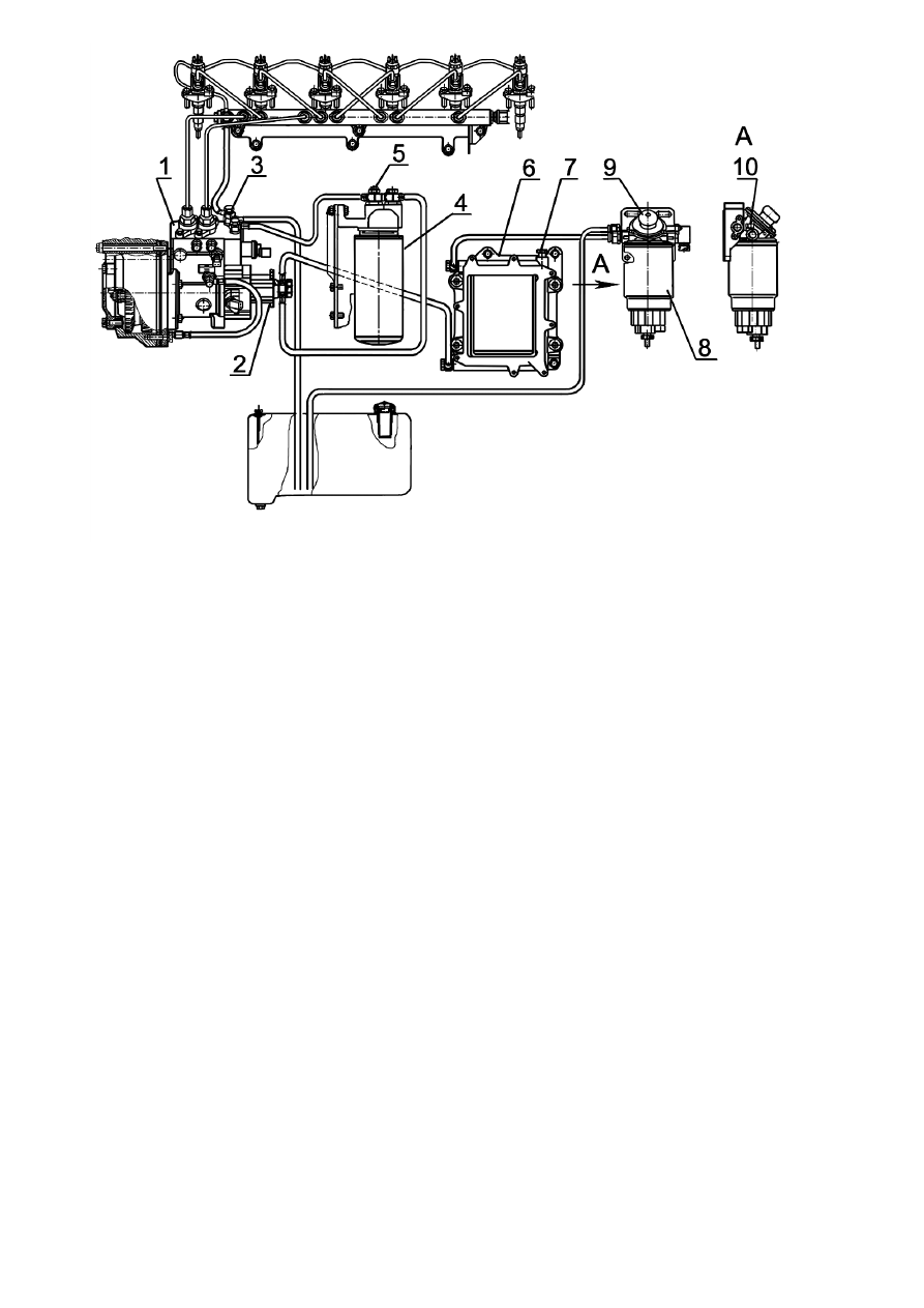
1-  High pressure fuel injection pump;  2  –  fuel priming pump; 3 –  drainage pipelines turn-elbow bolt 
drainage pipelines turn-elbow bolt; 4 – fine fuel filter; 5 – plug; 6 – ECU radiator; 7 – air outlet plug; 8 – 
coarse fuel filter; 9 – hand booster pump; 10- air outlet plug;   

Fig. 22 - Removing air from the fuel system 

Switching over to the “winter” or “summer” operation period and, therefore, changing 
the type of fue, to speed up the fuel system filling, use all available plugs for letting air out 
and do step-by-step air removal through plugs 10, 7, 5 and turn-elbow bolt 3. 

3.2.11 Servicing the air cleaner 
Servicing the air cleaner with a papter filterelement made of special highly porous card-
board is done after every 500 engine operation hours or, if necessary, by the indication of 
the clogging signalizer. Servicing the air cleaner includes purging of the main filter ele-
ment, which retains dust coming into the air cleaner. The control filter element clogging 
says for damage of the main filter element (paper curtain broken, bottoms coming off). In 
this case it is necessary to purge the control filter element and replace the main one.  
Servicing the air cleaner as shown on Fig.20 is done in the following order: 
- remove the monocyclone; clean the screen, the swirler and the monocyclone outlet holes 
from dust and dirt;  
- remove tray 6; 
- remove main filter element 1. 
It is not recommended to take control filter element 2 out of the housing. 
Blow the main filter element with compressed air, first the inside and then the outside 
unitll complete dust removal. To avoid the paper curtain breaking, the compressed air 
pressure should not exceed 0,2-0,3MPa. 


1 – main filter element; 2 – control filter element; 3 – gasket; 4 – wing-nut; 5 – ring; 6 – tray; 7 – housing, 
8 - monocyclone 

   Fig. 23 - Air cleaner 


Air flow must be directed at an angle relative to the filter element surface. When serviced, 
the filter element must be protected from mechanical damage and oiling.  
It is not permissible to purge the filter element with exhaust gases or wash it with diesel 
fuel.  
Clean the inlet pipe, the air cleaner housing and tray inner surfaces from dust and dirt. 
Before assemblying the air cleaner, check the sealing rings condition.  
When assemblying, make sure the filter elements are correctly installed in the housing and 
properly tighten the wing-nut by hand.  
3.2.12  Checking the air cleaner and the inlet duct connections hermeticity 
  
Checking the hermeticity of the air cleaner and the inlet duct connections is done during 
TM-2. To check the hermeticity use device 

КИ-4870 ГОСНИТИ. With this device unavail-

able, check the hermeticity visually. 

3.2.13 Washing the engine breathers 
 
The engine breathers must be washed with diesel fuel after every 2 000 hours of engine 
operation. To do that, remove the breathers housings, take the breathers out of the cylin-
der heads cover caps, wash them and purge with compressed air. Put the breathers and 
breathers housings back in place. 


3.2.14 Tightening the cylinder heads mounting bolts 
The cylinder heads mounting bolts tightening is done after every 1 000 operation hours on 
a hot engine in the following order:  
- remove the caps and the cylinder heads covers; 
- remover the rocker axles together with the rockers and the brackets; 
- using a dynamometric spanner tighen all of the cylinder heads mounting bolts, prelimi-
narily having loosened them by 1/6 of a turn in thre stages: 
while installing cylinder heads gaskets 714-63-09 (260-1003020): torques 1) 50

±

10 N·m, 

2) 170

±

10 N·m, 3) 240

±

10 N·m.  

while installing cylinder heads gaskets 719-73-08 (263-1003020): torques 1) 50

±

10 N·m, 

2) 190

±

10 N·m, 3) 260+10 N·m.  

The sequence of tightening is shown on Fig.24. 
After tightening the cylinder heads mounting bolts, put the rocker axles back in place and 
adjust the gap between the rockers and the valves as described in item 3.2.15. Put the cy-
linder heads covers and the covers caps back in place.  


Fig. 24- Sequence of cylinder heads mounting bolts tightening 


3.2.15  Checking the gaps between the valves and the rockers 

 
Checking and adjusting the gaps between the valves and the rockers is done after every 
500 operation hours preceded by checking of the cylinder heads mounting bolts tightening 
or, if necessary, on a cold engine (the water and oil temperature must not exceed 60º

С). 

The gap between the valve stems ends and the rocker strikers must stay within 0,25

05

,

0

10

,

0

+

mm 

for intake valves and 0,45

05

,

0

10

,

0

+

 mm foe exhaust valves. 

When adjusting the gap between a valve stem end and a rocker striker on a cold engine 
keep to:  

- intake valves - 0,25

05

,

0

 mm; 

- exhaust valves - 0,45

05

,

0

 mm; 

Do adjustment in the following order:  
- remove the cylinder heads cover caps and check the rocker axles brackets mounting bolts 
tightening; 
  

This image cannot currently be displayed.


- rotate the crankshaft till the first cylinder valves overshoot (the first cylinder intake valve 
starts opening and the exaust valve ends closing);  
- adjust the gaps of the third, fifth, seventh, tenth, eleventh and twelveth valves (counting 
from the fan), then rotate the crankshaft by one turn setting the overshoot in the sixth cyl-
inder and adjust the gaps of the first, second, fourth, sixth, eighth and nineth valves.   
To adjust the gaps, loosen locknut 2 of adjustment screw 3 as shown on Fig.25 and, screw-
ing or unscrewing the screw, set the required gap per feeler rod 1 between the rocker 
striker and the valve stem end.  
Having set the gap, tighten the locknut and check the gap with the feeler rod again turning 
the bar. Adjustment finished, put the cylinder heads cover caps back in place.  
The valves may be adjusted also in each cylinder when the piston is in the top dead center. 
To do that, turn the crankshaft till the first cylinder piston reaches the top dead center cor-
responding to the end of the compression stroke (the setting pin indicator on the gas dis-
tribution gears cover and the TDC mark on the torsional vibrations damper housing scale 
coincide)  and adjust the first cylinder valves gap.  
Rotate the crankshaft by 1/3 of a turn and adjust the gaps of the fifth cylinder valves. At 
that, the valves gaps must be adjusted in the order corresponding to the cylinders firing 
order(1-5-3-6-2-4) with rotating the crankshaft by 1/3 of a turn clockwise.  


                                        1 – feeler rod; 2- locknut; 3 – adjustment screw 
 

Fig. 25 – Adjusting the valves gaps 

3.2.16  The “COMMON RAIL” system maintenance 
The “COMMON RAIL” system maintenance is done at specialized service centers by the 
specialists of the“COMMON RAIL”system specialized service centers.  
Replacement of injectors after the “COMMON RAIL” system testing is done taking into 
account an injector and a nozzle labeling applied in the locations shown on Fig.26. 
Replacing an injector or a nozzle without using special equipment and specially trained 
staff, as well as within the warranty period, is not permissible. Replacing an injector noz-
zle during the warranty period may be done only by a BOSCH service center or by a 
BOSCH authorized workshop.  


Content   ..  32  33  34  35   ..