Diesel engines D-260.1S3А, D-260.2S3А, D-260.4S3А. Manual - part 33
 

  Index      Engines     Diesel engines D-260.1S3А, D-260.2S3А, D-260.4S3А - service manual


Search            


Content   ..  31  32  33  34   ..


Diesel engines D-260.1S3А, D-260.2S3А, D-260.4S3А. Manual - part 33


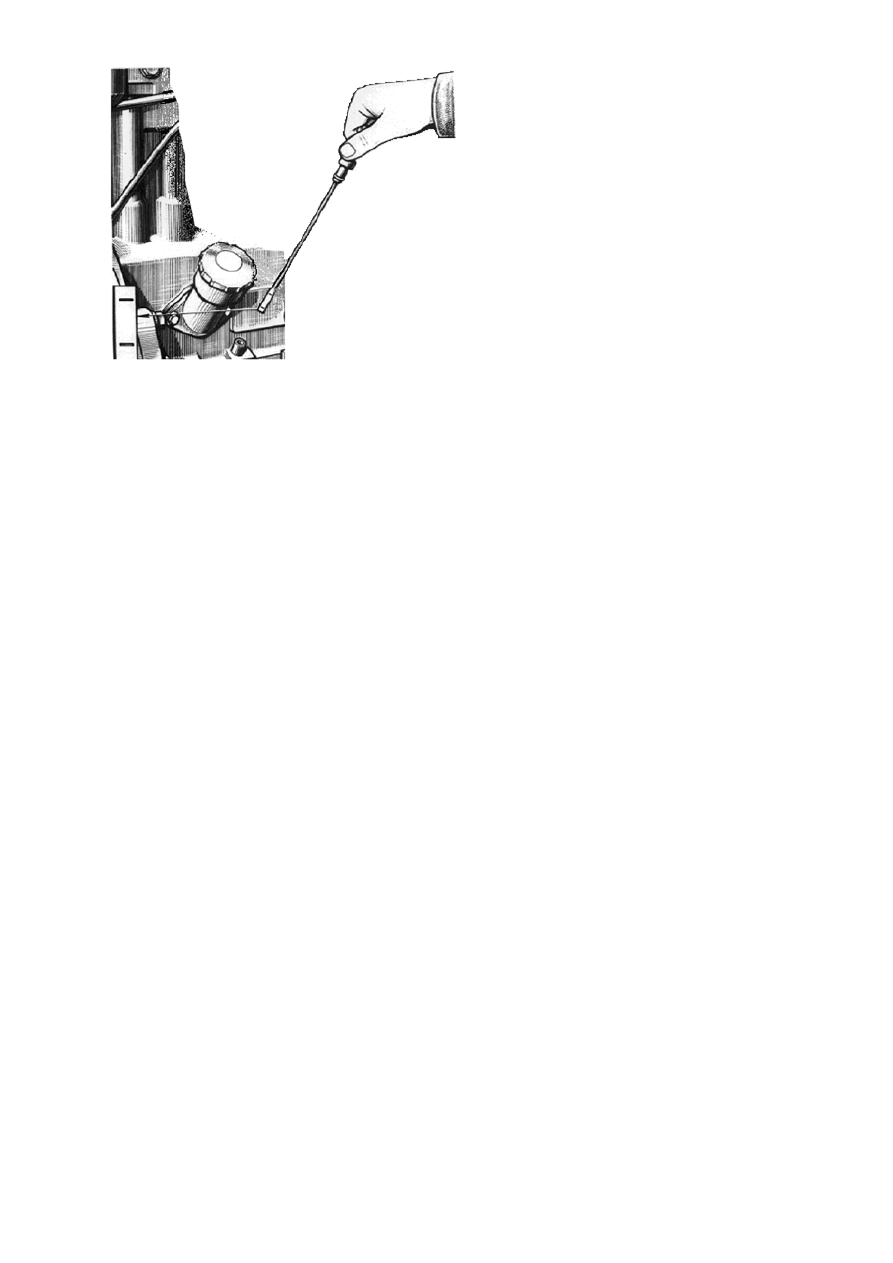
Fig. 18- Checking oil level in the engine oil sump. 

3.2.4 Replacing oil in the engine oil sump 
Oil in the diesel engine oil sump must be replaced after every 250 operation hours and in 
case of using lower quality analogous oils or fuel with highsulphur contents – after every 
125 operation hours.  
Drain used oil only from a heated engine. To drain the used oil, screw out the oil sump 
plug. A soon as all of the oil is out screw the plug back in place. Pour new oil through the 
oil filling branch up to the oil gauge upper mark.  Fill the oil sump only with the oil rec-
ommended by this Manual, according to the season of operation.  
  3.2.5  Replacing he oil filter Replacing he oil filter 
Oil filter must be replaced after every 10 thousand of vehicle run or upon the results of the  
“COMMON RAIL” system diagnostics, as shown on Fig.19, in the following order:  
- unscrew filter 

ФМ 037-1012005 from connector 3 using a special spanner or other tools 

available; 
- screw a new 

ФМ 037-1012005 (OJSC «Avtoagregat», Livny, Russia) filter on the con-

nector. When mounting the filter on the connector, apply motor oil on gasket 4. As soon as 
the gasket touches the housing base surface of filter 1, screw the filter further for 3-4 
turns. The filter on housing mounting must be done with hands only.  

In the future, order oil filter 

ФМ 037-1012005 at: 303858, Russia, the Oriol Region, 

Livny, 2

а Industrialnaya Street, OJSC “Avtoagregat”. 


1 – filter housing; 2 – filter; 3 – connector; 4 – filter gasket; 5 – anti-drainage valve;   6 – spring; 7 – by-
pass valve. 

Fig. 19 – Oil filter 

3.2.6 Cleaning the centrifugal oil filter rotor 
Cleaning the centrifugal oil filter rotor is done simultaneously with oil replacement in the 
engine oil sump. 
As shown on Fig. 20, unscrew nut 1 of the centrifugal oil filter cap 2 mounting and remove 
it. Check for presence of the balance mark in the rotor housing cup (put the mark, if it is 
not there). Lock the rotor from turning, for that purpose put a screw driver or a rod be-
tween the filter housing and the rotor bottom and, turning nut 4of the rotor cup mounting   
with a spanner, remove rotor cup 3. 
Check the rotor filtering screen 5 condition, clean and wash it, if necessary.  
Using a non-metalic scraper, remove the sediments from the rotor cup inner walls. 
Before assemblying the cup with the rotor housing, apply motor oil on the rubber sealing 
ring. Align the balancing marks on the cup and the rotor housing. The cup mounting nut 
should be screw with little effort until complete cup fitting on the rotor. After assemblying, 
the rotor must rotate freely without jamming with a move by hand.   
Put the centrifugal oil filter cap back in place and screw the cap nut at 35...50 N·m. 


                      1–nut; 2-cap; 3-cup; 4-special nut; 5-filtering screen 

Fig. 20 – Cleaning the centrifugal oil filter rotor. 

   3.2.7 Sediment removal from fuel pre-filter 
See tractor/ machine Operation & Maintenance Manual. 

      3.2.8 Fuel pre-filter replacement Replacing fuel pre-filter 
See tractor/ machine Operation & Maintenance Manual. 
Fill the system with fuel after filter assembly.  

3.2.9 Replacing fine fuel filter 
Fine fuel filter service life depends on the purity of the fuel used.  
Fine fuel filter is replaced after every 6oo hours of operation or upon the results of the 
“COMMON RAIL” system diagnostics as shown on Fig.21, for that purpose:  
- unscrew filter 1 from connector 7 in housing 2 and replace it by a new filter Mann & 
Hummel WDK962 shippedassembled together with gasket 6, which must be preliminarily 
oiled with motor oil; 
- as soon as gasket 6 touches mounting surface “A” on housing 2, further screw the filter 
in by ¾ of a turn. At that, the filter must be screwd further by hand only;  
- open the fuel tank tap and fill the sytem with fuel as described in item 3.2.10. 


1 – filter Mann 

& Hummel WDK962; 2 – filter housing; 3 – bracket; 4 – connector; 5 – plug (for letting 

out air); 6 – gasket; 7 – connector. 

Fig. 21- Replacing fine fuel filter. 

3.2.10  Filling the fuel system  Filling the fuel system 
To fill the fuel system, it is necessary to remove air from it (purge the system). For that 
purpose: 
Unscrew plug 5 (Fig. 22) located on the fine fuel filter outlet connector mounting bolt by 
2-3 turns.Purge the system with booster (priming) pump 9 located on fuel coarse filter 
housing 8, screw plug 5 in (torque – 7…8 Nm) when you see fuel coming out without air 
bubbles.  
Unscrew turn-elbow 3 bolt of the fuel drainage pipelines mounting on HPFIP housing 1 
by 2…3 turns and continue purging by the booster pump until you see fuel coming out 
without air bubbles. Screw bolt 7 (torque 3…4 Nm). 


Content   ..  31  32  33  34   ..