Diesel engines D-260.1S3А, D-260.2S3А, D-260.4S3А. Manual - part 8
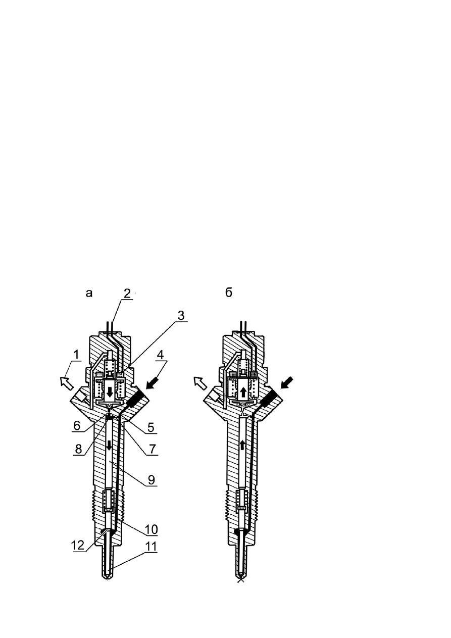
Fig. 9 – Injector
Forming of the injector control signals by ECU works based on reading the signals
formed by the crankshaft and the HPFIP camshaft speed sensors (sensors 2 and 5, Fig.2,
Annex
Д), installed in a consistent relationship in a specific pattern.
The injectyor operation principle is shown on Fig.10.
The fuel is supplied along the high pressure pipeline via inlet channel 4 to the atomizer of
injector 11 and also through a fuel supply throttle hole 7 – to the chamber of controlling
valve 8. Through the fuel outlet throttle hole, which may be opened by the electromagnet-
ic valve, the chamber is connected with back runoff duct 1.
With closed throttle hole 6 the hydraulis force acting from above on the controlling valve
piston is higher the force of the fuel pressure on the atomizer needle cone underneath. As
a result the needle is pressed to the atomizer seat and firmly closes the atomizer holes
and the fuel cannot get in the combustion chamber.
When electromagnetic valve 3 triggers, the electromagnet armature is moved up opening
throttle hole 6. Accordingly, reduced are both – the pressure in the controlling valve
chamber and the hydraulic force applied on the controlling valve piston. By fuel pressure
on the cone the atomizer needle moves away from the valver seat, so the fuel get in the
cylinder combustion chamber through the atomizer holes. The controlling supply – an
additional fuel amount meant for the needle rise which is further diverted to the fuel back
runoff duct.