Diesel engines D-260.1S3А, D-260.2S3А, D-260.4S3А. Manual - part 9
 

  Index      Engines     Diesel engines D-260.1S3А, D-260.2S3А, D-260.4S3А - service manual


Search            


Content   ..  7  8  9  10   ..


Diesel engines D-260.1S3А, D-260.2S3А, D-260.4S3А. Manual - part 9


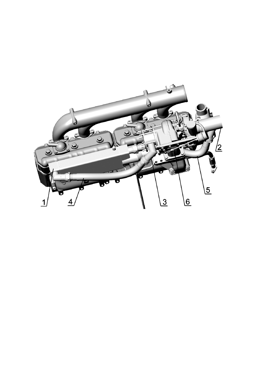
The functioning of the device is maintained by delivery of a portion of exhaust gas from 
the exhaust manifold via the EGR cooler into the intake manifold, as a result of the natu-
ral difference between the exhaust gas pressure in front of the turbine and that of the 
charge air. 
The presence of exhaust gases in the air charge coming to the engine cylinders provides 
froming of local zones in the combustion process allowing to reduce the amounts of ni-
trogene oxides. Afterburning of carbon monoxide and hydrocarbons also contributes to 
improving the eclological parameters of exhaust gas contents. 


1 – recirculated exhaust gas cooler; 2* – mixer; 3 *– spacer;  4 – recirculated exhaust gas inlet branch 
pipe from turbocharger to EGR; 5 - recirculated exhaust gas inlet branch pipe from cooler to mixer; 6 – 
turbocharger. 
*  -  the recirculated exhaust gas inlet and outlet elements design may be different with developers of 
tractors or agricultural machines for the reason proper fitting in a vehicle and must be approved  with 
MMP.  

Fig. 13 – Exhaust gas recirculation device 

1.2.2.6.7  Diesel engine gas exchange system  

The diesel engine gas exchange diagram together with breathers is shown on Fig.14.   
Breather is designed to prevent excessive pressure in the lubrication system created by 
the exhaust gas penetrating into the oil sump through the gas joints of the cylinder-piston 
group and oil injection into the atmosphere.   
In the implemented gas exchange system the crankcase gases, via the channels in the cyl-
inder block and the cylinder head, come into the cavity formed by the cylinder head cover 
and the cover cap. Breather housing 1 (Fig. 14) is mounted on cover cap 4 of the cylinder 
head. The crankcase gases rush through the slots of cup 6 into breather housing 1 under 
the influence of the pressure difference in the atmosphere and in the cavity of the cylinder 
head cover. Having got into the cup cavity, the crankcase gases expand and strike against 
oil deflector 2, lose their energy and cool down. As a resul,t a significant portion of the 
oil mist falls down as oil. The crankcase gases cleaned from oil then get into the atmos-
phere. 


                        1 – breather housing; 2 – oil deflector; 3 – cup; 4 – cover cap 

Fig.14   Diesel engine gas exchange diagram 

1.2.2.7 Cooling system 
Closed type cooling system (Fig.15) with forced circulation of cooling liquid from a cen-
trifugal pump. The water pump is driven in rotation by a V-belt from the crankshaft pul-
ley. Lubricant "Litol-24"is placed in the bearing cavity of the pump at the pump assem-
bly. The bearing does not need lubrication in the process of use.  
The cooling liquid temperature in the cooling system must be kept within 85º 

С - 95º С. 


1 – water pump; 2 – thermostats; 3 – cylinder block; 4 – liquid-oil heat exchanger;  5– radiator; 6 – fan; 
7 – recirculated exhaust gases cooler; 8 – recirculated gases inlet pipe; 9 – thermostat housing; 10 – pis-
ton; 11 – main valve;    12 – by-pass valce; 13 – thermal force element; 14 – valve spring; 15 – by-pass 
valve spring; 16 – compressor (for diesel engines with liquid cooled compressor)  

Fig. 15 – Cooling system diagram. 

For faster diesel engine warming up after start and automatic regulation of temperature 

mode at various loads and amvient temperatures two ТС-107 thermostats are installed on 
the purging line.  
Ther are two valves (the main 11 and bypass 12, Fig.15) in the thermostat housing and 
thermal force element 13, inside which there is piston 10  
The thermal force element consists of housing (cylinder) filled with thermosensitive sub-
stance expanding with warming up. Fixed firm on the housing is the main valve. On the 
housing axis valve 12 is mounted, pressed by spring 15. Spring 14 is installed so that it 
firmly presses the main valve to the housing of thermostat 9. 

After the engine start, before the cooling liquid warms up to +85ºС, the main thermostat 
valves are closed. The cooling liquid from the cylinder head water outlet pipe, passing by 
the radiator, goes to the pump and once again gets back to the cylinder block.  

At the cooling liquid temperature over 85ºС, the substance filling the thermosensitive el-
ement expanda and affects fixedly mounted piston 10, thus causing movement of the 
thermosensitive element with the main valve relative to the piston. With the force of 
movement exceeding the force created by valve 14, the main valve moves down thus cre-
ating a gap between the main valve and the thermostat hiusing, and the cooling liquid 


then starts partially circulating through the radiator. When the cooling liquid tempera-

ture reaches +90ºС, the main valve opens completely and the entire flow goes through 
the radiator. Simultaneously with the main valve movement, the bypass valve also moves 
down, shutting the channel of cooling liquid bypass to the water pump. 
 Installed in the engine is a water pump complete with a fan. The fan is fixed to the pulley. 
 On the diesel engine D-260.4S3A combine harvester modification, the water pump is in-
stalled without fan, since air supply to radiator is done by a fan installed in the combine 
harvester. 
 There are two options for fan installation: with a space plate and without it (Fig. 16).   
On some diesel engine modifications, instead of steel fan they may install a moulded plas-
tic fan 245-1308040-

А (Ø510 mm). 


а – without space plate;                        б – with space plate. 


1-blade, 2-bolt, 3-washer, 4-space plate, 5-bolt, 6-washer, 7- rivet, 8-cross piece. 


Fig. 16– Fan mounting 


1.2.2.8  Supercharging device 

1.2.2.8.1  Turbocharger 


Content   ..  7  8  9  10   ..