DDFP SERIES ENGINES FOR FIRE PUMP APPLICATIONS MP-4. Manual - part 13
 

  Index      Engines     DDFP SERIES ENGINES FOR FIRE PUMP APPLICATIONS MP-4 - service manual


Search            


Content   ..  11  12  13  14   ..


DDFP SERIES ENGINES FOR FIRE PUMP APPLICATIONS MP-4. Manual - part 13


DDFP

SECTION 3.6

Page 44

TYPE T COUPLING INSTALLATION &
ALIGNMENT DATA

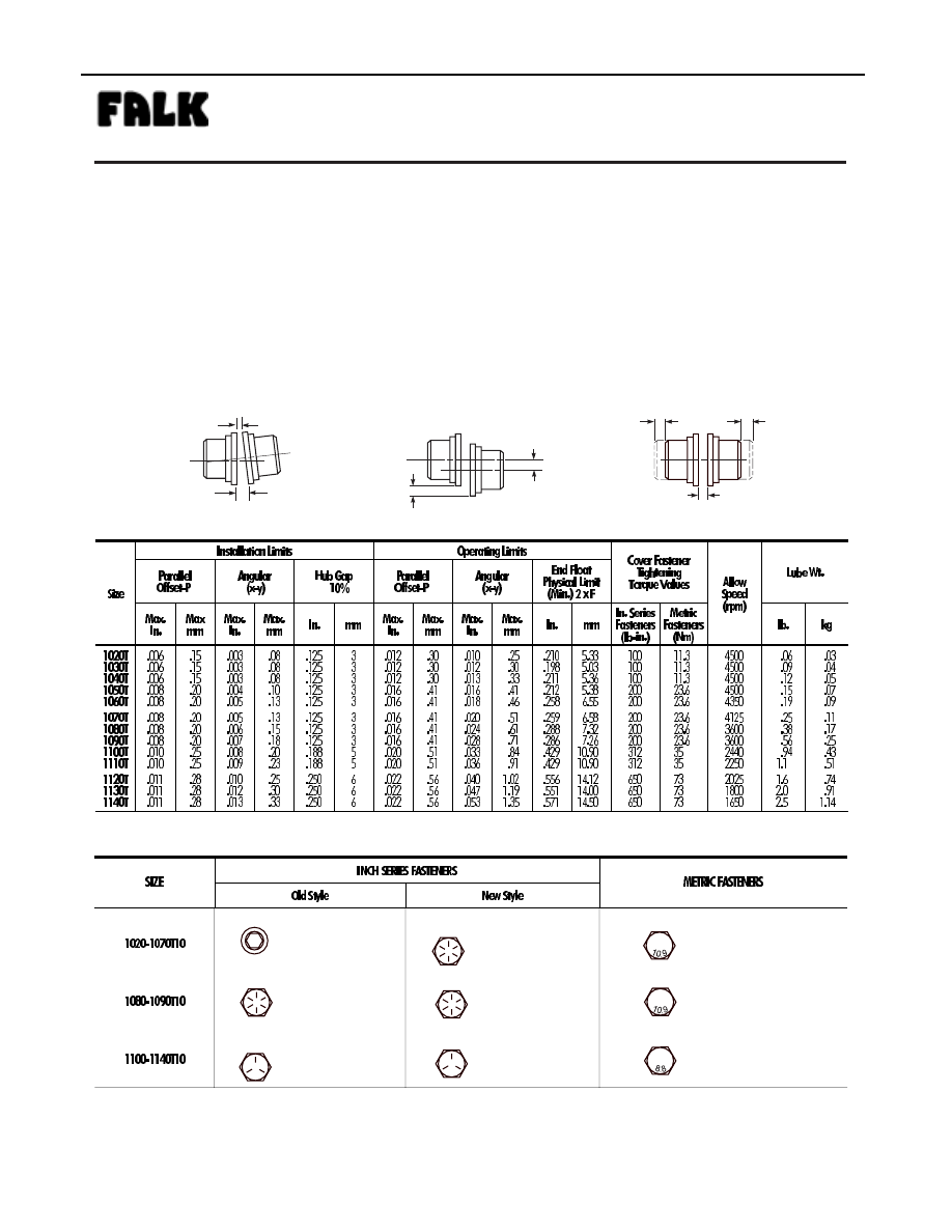
Maximum life and minimum maintenance for the coupling and
connected machinery will result if couplings are accurately
aligned. Coupling life expectancy between initial alignment and
maximum operating limits is a function of load, speed and
lubrication. Maximum operating values listed in Table 2 are
based on cataloged allowable rpm.

Values listed are based upon the use of the gaps listed,
standard coupling components, standard assemblies and
cataloged allowable speeds.

Values may be combined for an installation or operating condition.

Example: 1060T max. operating misalignment is .016" parallel
plus .018" angular.

NOTE: For applications requiring greater misalignment, refer
application details to the Factory.

Angular misalignment is dimension X minus Y as illustrated below.

Parallel misalignment is distance P between the hub center lines
as illustrated below.

End float (with zero angular and parallel misalignment) is the axial
movement of the hubs(s) within the cover(s) measured from“O” gap.

SAE Grade 8

SAE Grade 8

SAE Grade 5

SAE Grade 8

SAE Grade 8

SAE Grade 5

Property Class 10.9

Property Class 10.9

Property Class 8.8

TABLE 2 — Misalignment & End Float

Type T10

 •

Sizes 1020 –1140 & 20–140        (Page 5 of 6)

Steelflex ® Couplings

Installation and Maintenance

®

a good name in industry

1

 Older style covers, Sizes 1020T10 thru1070T10 must utilize socket head cap screws and locknuts held by the cover.

±

TABLE 3 — Coupling Cover Fastener Identification

ANGULAR MISALIGNMENT

PARALLEL MISALIGNMENT

END FLOAT

F

F

P

P

X

GAP

Y

DDFP

SECTION 3.6

Page 45

PARTS IDENTIFICATION

All coupling parts have identifying part numbers as shown
below. Parts 3 and 4 (Hubs and Grids), are the same for both
Type T10 and T20 couplings. All other coupling parts are unique to
Type T10. When ordering parts, always SPECIFY SIZE and TYPE
shown on the COVER.

PARTS INTERCHANGEABILITY

Parts are interchangeable between Sizes 20T and 1020T, 30T
and 1030T, etc. except as noted.

GRIDS — Size 1020T thru 1140T Steelflex couplings use blue
grids. Older models, 20T thru 140T, use orange grids.

CAUTION: Blue grids may be used in all applications, but DO
NOT substitute orange grids for blue.

COVERS —

CAUTION: DO NOT mix cover halves of different

designs. Sizes 1020T thru 1070T10 covers have been
manufactured in several different two-rib designs and 80T thru
140T covers have been manufactured with two and three ribs.

HARDWARE ó Older style covers, Sizes 1020T10 thru
1070T10, utilized socket head cap screws with captured
locknuts. The new style covers use hex head cap screws (either
inch or metric) and unrestrained locknuts. Specify either inch
series SOCKET head or inch or metric series HEX head cap
screws when ordering replacement parts.

PART NUMBERS

1. Seal (T10)

2. Cover (T10)

3. Hub (Specify bore

and keyway)

4. Grid

5. Gasket (T10)

6. Fasteners (T10) ó Coupling

may be supplied with one
set each of inch series fas-
teners and metric fasteners.

7. Lube Plug

SIZE &
PART
NUMBER

ORDER INFORMATION

1. Identify part(s) required by

name above.

2. Furnish the following

information.

EXAMPLE:

Coupling Size: 1030
Coupling Type: T10
Model: B
Bore: 1.375
Keyway: .375 x .187

3. Price parts from Price List

422-110 and appropriate
discount sheet.

PART NUMBER LOCATION

(1.) SEAL

(3.) HUB

SIZE

PART NUMBER

(4.) GRID

(2.) COVER

(6.)

1030

T

10

B

(5.) GASKET

(7.)

PART NUMBER

COUPLING
SIZE

TYPE

MODEL

PRODUCT
CLASSIFICATION

SIZE

SIZE, PART NUMBER &
BORE

(Page 6 of 6)

Steelflex ® Couplings

Installation and Maintenance

Type T10

Sizes 1020 –1140 & 20–140

®

a good name in industry

DDFP

SECTION 4

ENGINE TUNE-UP

There is no sc heduled inter val for performing an eng ine

tune-up. As long as the eng ine is perf orming satisfactorily,

no tune-up should be necessary.

SPEED CONTROL

The engine speed is pre-set at the factory to correspond to the

full load pump installa tion requirement. In accor dance with

NFPA-20 requirements, this is a tamper-proof mechanism.

NOTE:

This engine has no idle speed setting. 

If engine performance is not sa tisfactoy, contact your local

D.D.C. Distributor/Dealer.

If required, an engine repair manual may be obtained fr om

the authorized D.D.C. Distributor/Dealer in your area.

A mechanical governor controls the engine speed. The gov-

ernor is a flyweight force versus spring force device that will

control the rate of fuel delivery to the engine so as to balance

the two forces. The solenoid on the governor is only used to

set the go vernor to the R UN or ST OP position. Speed ad-

justment is possible by adjusting the spring force via a tam-

per proof mechanism.

All governors are adjusted to the FM/UL/ULC nameplate

BHP and 

full load

pump speed before lea ving Clark e

D.D.A. During Start-Up Inspection or when placing recon-

ditioned units into service, some minor speed adjustments

may be required. It is recommended that this adjustment be

performed by  the authorized Detroit Diesel Distrib utor or

Dealer representative.

The governor is located as follows:

I-53 Series

at the upper left rear of engine

I-71 Series

at the upper right front of engine

V Series

at the front of blo wer in the v ee of the

block.

See page 43 for the identif ication of the engine series for a

specific model.

Figure 1 shows a typical I-53 Series engine governor. In this

picture, the cover has been remo ved to e xpose the mecha-

nism for adjusting engine speed. By loosening the jam nut

next to the go vernor body, the adjusting nut can then be

rotated clockwise to increase engine speed and counter-

MECHANICAL GOVERNOR - SPEED ADJUSTMENT

clockwise to reduce engine speed.

Figure 2 pro vides the speed adjustment instructions for 71

and 92 Series engines.

ATTENTION:

D.D.C. Distrib utor/Dealer Mechanic.  The

53 Series Governor High Speed Spring Gap

is .006" (.15mm) to be set @ zero RPM!

This governor does not have idle capability

or a buffer screw.

NOTE:

Be sure to resecure the jam nut after making

speed adjustments. Replace the co ver when ad-

Figure 1 - Speed Adjustment I-53 Series

Page 46

SECTION 4

DDFP

GOVERNOR SOLENOID-ADJUSTMENT

The mechanical governor is controlled by a DC solenoid. A

spring loaded yield link is included as part of the e xternal

linkage from the run/stop lever to governor solenoid.

IMPORTANT:

To insure the engine will produce rated

nameplate horsepo wer, the g ap be-

tween the yield link and the solenoid

plunger must be properly adjusted.

(Refer to Figure 3.)

YIELD LINK GAP CHECK

Position the mode selector switch on the instrument panel

(Fig. 3, Page 32), to the MANUAL position. Manually push

the solenoid plunger into the solenoid.  When the plunger is

at full tra vel, the hold coil magnetic f ield will hold the

plunger, linkage and the run/stop le ver in the run position.

Push on the plunger spring bolt, not the linkage or the lever.

Check the gap at the narrowest point and adjust if necessary,

(Refer to Fig. 3).  After the check is completed return the

mode selector switch to the AUTOMATIC position.

WARNING:

DO NOT lea ve the MODE SELECT OR

switch in the MANU AL R UN position

during  AUTOMATIC operation. (The

controller will be una ble to stop the

engine and O VERHEAT D AMAGE

WILL RESULT)

Page 46-A

53 SERIES ENGINES

Adjust the Gap by loosening the Lever Clamping Bolt (Fig.

3), and rotating the Run/Stop Lever on the governor shaft to

the desired position and re-torque the clamping bolt. Re-

check the gap and repeat adjustments if necessary. After the

check is completed return the mode selector switch to the

AUTOMATIC position.

After the gap has been properly adjusted, and with the gov-

ernor solenoid de-ener gized, in the ST OP position, adjust

the Plunger Stop Bolt. Set at zero clearance with the Plunger

Spring Bolt, then turn one full turn clockwise and lock with

the Jam Nut.

WARNING:

DO NOT lea ve the MODE SELECT OR

switch in the MANU AL R UN position

during  AUTOMATIC operation. (The

controller will be unable to stop the

engine and O VERHEAT D AMAGE

WILL RESULT)

When the adjustments have been completed, start the engine

from the ENGINE CONTROLLER (AEC), using the MAN-

UAL mode. Verify the Gap Dimension again, then stop the

engine. Return all controls to the AUTOMATIC mode.

Figure 3 - Shown in the Energized/Run Position

Figure 2 - Speed Adjustment 71 & 92 Series


Content   ..  11  12  13  14   ..