DDFP SERIES ENGINES FOR FIRE PUMP APPLICATIONS MP-4. Manual - part 12
 

  Index      Engines     DDFP SERIES ENGINES FOR FIRE PUMP APPLICATIONS MP-4 - service manual


Search            


Content   ..  10  11  12  13   ..


DDFP SERIES ENGINES FOR FIRE PUMP APPLICATIONS MP-4. Manual - part 12


DDFP

SECTION 3.6

Page 40

How To Use This Manual

This manual provides detailed instructions on maintenance,
lubrication, installation, and parts identification. Use the table
of contents below to locate required information.

Table of Contents

CAREFULLY FOLLOW THE INSTRUCTIONS IN THIS
MANUAL FOR OPTIMUM PERFORMANCE AND TROUBLE
FREE SERVICE.

INTRODUCTION

This manual applies to Sizes 1020T thru 1140T and 20T thru
140T10 Falk SteelfIex Tapered Grid Couplings. Unless
otherwise stated, information for Sizes 1020T thru 1140T
applies to Sizes 20T thru 140T respectively, e.g. 1020T = 20T,
1100T = 100T, etc. These couplings are designed to operate
in either the horizontal or vertical position without modification.
Beginning in 1994, these couplings are being supplied with
one set of inch series fasteners and one set of metric fasteners.
Use either set of fasteners, depending on your preference.
Refer to Page 6 for part interchangeability.

The performance and life of the couplings depend largely upon
how you install and service them. Carefully follow the
instructions in this manual for optimum performance and
trouble free service.

CAUTION: Consult applicable local and national safety codes
for proper guarding of rotating members. Observe all safety
rules when installing or servicing couplings.

WARNING: Lockout starting switch of prime mover and remove
all external loads from drive before installing or servicing couplings.

LUBE FITTINGS

Cover halves have

1

/

8

NPT Iube holes. Use a standard grease

gun and Iube fitting as instructed on Page 4.

LIMITED END FLOAT

When electric motors, generators, engines, compressors and
other machines are fitted with sleeve or straight roller bearings,
limited axial end float kits are recommended for protecting the
bearings. Falk Steelflex couplings are easily modified to limit
end float; refer to Manual 428-820 for instructions.

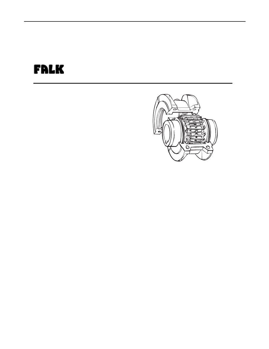
TYPE T10 STEELFLEX COUPLING

LUBRICATION

Adequate lubrication is essential for satisfactory operation. Page
2 provides a list of typical lubricants and specifications for
general purpose and long term greases. Because of its superior
lubricating characteristics and low centrifuge properties, Falk
Long Term Grease (LTG) is highly recommended. Sizes 1020T
to 1090T10 are furnished with a pre-measured amount of
grease for each coupling. The grease can be ordered for larger
size couplings.

The use of general purpose grease requires re-lubrication of the
coupling at least annually.

Long Term Grease (LTG)

The high centrifugal forces encountered in couplings separate
the base oil and thickener of general purpose greases. Heavy
thickener, which has no lubrication qualities, accumulates
in the grid-groove area of Steelflex couplings resulting in
premature hub or grid failure unless periodic lubrication cycles
are maintained.

Falk Long Term Grease (LTG) was developed specifically for
couplings. It resists separation of the oil and thickener and is an
extreme pressure grease.

Steelflex couplings initially lubricated with LTG will not require
re-lubrication until the connected equipment is stopped for
servicing. If a coupling leaks grease, is exposed to extreme
temperatures, excessive moisture, or experiences frequent
reversals, more frequent lubrication may be required.

Although LTG grease is compatible with most other coupling
greases, the mixing of greases may dilute the benefits of LTG.

USDA Approval

LTG has the United States Department of Agriculture Food
Safety & Inspection Service approval for applications where
there is no possibility of contact with edible products. (H-2
ratings).

CAUTION: Do not use LTG in bearings.

Steelflex ® Couplings

Installation and Maintenance

Type T10

 •

Sizes 1020 –1140 & 20–140

(Page 1 of 6)

a good name in industry

Introduction. . . . . . . . . . . . . . . . . . . . . . . . . . . . . . . . . . . . . . . . . . . . . . . . . Page 1
Lube Fittings. . . . . . . . . . . . . . . . . . . . . . . . . . . . . . . . . . . . . . . . . . . . . . .. Page 1
Limited End Float. . . . . . . . . . . . . . . . . . . . . . . . . . . . . . . . . . . . . . . . . . Page 1
Lubrication. . . . . . . . . . . . . . . . . . . . . . . . . . . . . . . . . . . . . . . . . . . . . . Pages 1-2
Installation & Alignment Instructions. . . . . . . . . . . . . . . . . Pages 2-4
Annual Maintenance, Relube & Disassembly. . . . . . . . . .. Page 4
Installation & Alignment Data. . . . . . . . . . . . . . . . . . . . . . . . . . . . . Page 5
Parts Identification &Parts Interchangeability. . . . . . . . . . . Page 6

DDFP engines are offered with a standard FALK drive hub,

(engine half only). See Page 41 for FALK coupling installa-

tion instructions.
If your engine includes this type coupling,please refer to the

following for service and maintenance information.

Other pump drive options available are vertical turbine drive

shaft adaptor or a standard engine flywheel. Neither of these

require regular maintenance, they are however, very critical

components and should recei ve weekly inspections during

the regular maintenance run.

FALK DRIVE HUB

Specifications — Falk LTG

The values shown are typical and slight variations are permissible.

AMBIENT TEMPERATURE RANGE — -20˚F (-29˚C) to 250˚F
(121˚C).

MINIMUM BASE OIL VISCOSITY — 3300SSU (715cST) @
100˚F (38˚C)

THICKENER — less than 12% by weight.

CENTRIFUGE SEPARATION CHARACTERISTICS — ASTM
#D4425 (Centrifuge Test) — K36 = 2/24 max., very high
resistance to centrifuging.

NLGI GRADE (ASTM D-217) — 

1

/

2

MINIMUM DROPPING POINT — with 60 stroke worked
penetration value in the range of 320 to 365 — 
350˚F (177˚C) min.

MINIMUM TIMKEN O.K. LOAD — 40 lbs.

ADDITIVES — Rust and oxidation inhibitors that do not corrode
steel or swell or deteriorate synthetic seals.

Packaging

14 OZ. CARTRIDGES — For use in standard grease guns.
Sufficient quantity to initially lubricate sizes thru 1090T.

35 LB. PAIL — Ideal for larger size couplings or many
smaller sizes.

120 LB. KEG & 400 LB. DRUM — For plants with central
storage areas. A pump with a pressurized follower plate is
required for dispensing grease.

CASE LOTS OF 24-14 OZ. CARTRIDGES — also available.

General Purpose Grease

Annual Lubrication — The following specifications and
lubricants for general purpose grease apply to Falk Steelflex
couplings that are lubricated annually and operate within
ambient temperatures of 0˚F to 150˚F (-18˚C to 66˚C). For
temperatures beyond this range (see Table 1), consult
the Factory.

If a coupling leaks grease, is exposed to extreme temperatures,
excessive moisture or experiences frequent reversals, more
frequent lubrication may be required.

Specifications — General Purpose Coupling
Lubricants

The values shown are typical and slight variations are
permissible.

DROPPING POINT — 300˚F (149˚C) or higher.

CONSISTENCY — NLGI No. 2 with 60 stroke worked
penetration value in the range of 250 to 300.

SEPARATION AND RESISTANCE — Low oil separation rate
and high resistance to separation from centrifuging.

LIQUID CONSTITUENT — Possess good lubricating properties
... equivalent to a high quality, well refined petroleum oil.

INACTIVE — Must not corrode steel or cause swelling or
deterioration of synthetic seals.

CLEAN — Free from foreign inclusions.

General Purpose Greases Meeting Falk
Specifications

Lubricants listed below are typical products only and should not
be construed as exclusive recommendations.

INSTALLATION OF TYPE T10 STEELFLEX
TAPERED GRID COUPLINGS

Installation

Only standard mechanics tools, wrenches, a straight edge and
feeler gauges are required to install Falk Steelflex couplings.
Coupling Sizes 1020T thru 1090T are generally furnished
for CLEARANCE FIT with setscrew over the keyway. Sizes
1100T and larger are furnished for an INTERFERENCE FIT
without a setscrew.

CLEARANCE FIT HUBS — Clean all parts using a non-
flammable solvent. Check hubs, shafts and keyways for burrs.
Do not heat clearance fit hubs. Install keys, mount hubs with
flange face flush with shaft ends or as otherwise specified and
tighten setscrews.

INTERFERENCE FIT HUBS — Furnished without setscrews. Heat
hubs to a maximum of 275˚F (135˚C) using an oven, torch,
induction heater or an oil bath.

When an oxy-acetylene or blow torch is used, use an excess
acetylene mixture. Mark hubs near the center of their length in
several places on hub body with a temperature sensitive crayon,
275˚F (135˚C) melt temperature. Direct flame towards hub bore
using constant motion to avoid overheating an area.

TABLE 1 — General Purpose Greases

(Page 2 of 6)

Steelflex ® Couplings

Installation and Maintenance

Type T10

Sizes 1020 –1140 & 20–140

®

a good name in industry

Page 41

DDFP

SECTION 3.6

DDFP

WARNING: If an oil bath is used, the oil must have a flash
point of 350˚F (177˚C) or higher. Do not rest hubs on the
bottom of the container. Do not use an open flame in a
combustible atmosphere or near combustible materials.

Heat hubs as instructed above. Mount hubs as quickly as possible
with hub flange face flush with shaft end. Allow hubs to cool before
proceeding. Insert setscrews (if required) and tighten.

Maximize Performance And Life

The performance and life of couplings depend largely upon
how you install and maintain them. Before installing couplings,
make certain that foundations of equipment to be connected
meet manufacturersí requirements. Check for soft foot. The use
of stainless steel shims is recommended. Measuring
misalignment and positioning equipment within alignment
tolerances is simplified with an alignment computer. These
calculations can also be done graphically or mathematically.

Alignment is shown using spacer bar and straight edge. This
practice has proven to be adequate for many industrial
applications. However, for superior final alignment, the use of
dial indicators (see Manual 458-834 for instructions), lasers,
alignment computers or graphical analysis is recommended.

1 — Mount Seals And Hubs

Lock out starting switch of prime mover. Clean all metal parts
using a non-flammable solvent. Lightly coat seals with grease
and place on shafts BEFORE mounting hubs. Heat interference
fit hubs as previously instructed. Seal keyways to prevent
leakage. Mount hubs on their respective shafts so the hub face
is flush with the end of its shaft unless otherwise indicated.
Tighten setscrews when furnished.

2 — Gap and Angular Alignment

Use a spacer bar equal in thickness to the gap specified in
Table 2, Page 5. Insert bar as shown below left, to same depth
at 90˚intervals and measure clearance between bar and hub
face with feelers. The difference in minimum and maximum
measurements must not exceed the ANGULAR installation limits
specified in Table 2.

3 — Offset Alignment

Align so that a straight edge rests squarely (or within the limits
specified in Table 2) on both hubs as shown above and also at
90˚intervals. Check with feelers. The clearance must not
exceed the PARALLEL OFFSET installation limits specified in
Table 2. Tighten all foundation bolts and repeat Steps 2 and 3.
Realign coupling if necessary.

4 — Insert Grid

Pack gap and grooves with specified lubricant before inserting grid.
When grids are furnished in two or more segments, install them so
that all cut ends extend in the same direction (as detailed in the
exploded view picture above); this will assure correct grid contact
with non-rotating pin in cover halves. Spread the grid slightly to
pass over the coupling teeth and seat with a soft mallet.

Type T10

 •

Sizes 1020 –1140 & 20–140        (Page 3 of 6)

Steelflex ® Couplings

Installation and Maintenance

®

a good name in industry

Page 42

SECTION 3.6

5 — Pack With Grease And Assemble Covers

Pack the spaces between and around the grid with as much
lubricant as possible and wipe off excess flush with top of grid.
Position seals on hubs to line up with grooves in cover. Position
gaskets on flange of lower cover half and assemble covers so
that the match marks are on the same side (see above). If shafts
are not level (horizontal) or coupling is to be used vertically,
assemble cover halves with the lug and match mark

UP or on the high side. Push gaskets in until they stop against
the seals and secure cover halves with fasteners, tighten to
torque specified in Table 2. Make sure gaskets stay in position
during tightening of fasteners. CAUTION: Make certain lube
plugs are installed before operating.

ANNUAL MAINTENANCE

For extreme or unusual operating conditions, check coupling
more frequently.

1. Check alignment per steps on Page 3. If the maximum oper-

ating misalignment limits are exceeded, realign the coupling
to the recommended installation limits. See Table 2 for in-
stallation and operating alignment limits.

2. Check tightening torques of all fasteners.

3. Inspect seal ring and gasket to determine if replacement is

required. If leaking grease, replace.

4. When connected equipment is serviced, disassemble the

coupling and inspect for wear. Replace worn parts. Clean
grease from coupling and repack with new grease. Install
coupling using new gasket as instructed in this manual.

Periodic Lubrication

The required frequency of lubrication is directly related to the type
of lubricant chosen, and the operating conditions. Steelflex
couplings lubricated with common industrial lubricants, such as
those shown in Table 1, should be relubed annually. The use of
Falk Long Term Grease (LTG) will allow relube intervals to be
extended to beyond five years. When relubing, remove both lube
plugs and insert lube fitting. Fill with recommended lubricant until
an excess appears at the opposite hole.

CAUTION: Make certain

all plugs have been inserted after lubricating.

Coupling Disassembly And Grid Removal

Whenever it is necessary to disconnect the coupling, remove
the cover halves and grid. A round rod or screwdriver that will
conveniently fit into the open loop ends of the grid is required.
Begin at the open end of the grid section and insert the rod or
screwdriver into the loop ends. Use the teeth adjacent to each
loop as a fulcrum and pry the grid out radially in even, gradual
stages, proceeding alternately from side to side.

MATCH MARK

LUG UP

VERTICAL COUPLINGS

(Page 4 of  6)

Steelflex ® Couplings

Installation and Maintenance

Type T10

Sizes 1020 –1140 & 20–140

®

a good name in industry

DDFP

SECTION 3.6

Page 43


Content   ..  10  11  12  13   ..