DDFP SERIES ENGINES FOR FIRE PUMP APPLICATIONS MP-4. Manual - part 11
DDFP
SECTION 3.5
Page 36
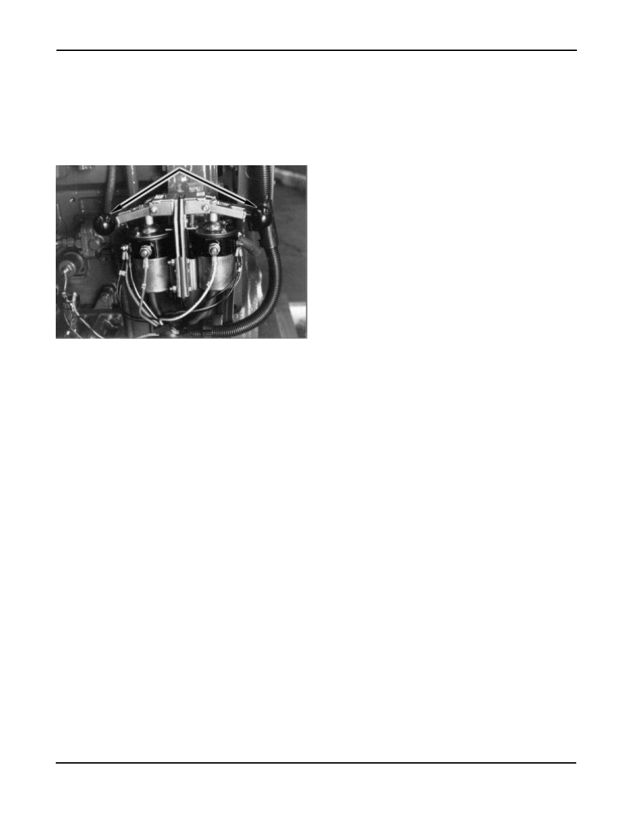
MANUAL CONTACTORS
Operate contactors to assure manual operation. If o ver-cen-
ter contact is not functional or if other inoperative condition
exist, replace the UNIT. Check bolts for tightness, wires for
tightness or damage. (Fig. 12).
BATTERY CHARGING ALTERNATOR
Inspect the terminals for corrosion and loose connections
and the wiring for broken wires. Replace or repair as neces-
sary. Service alternator with authorized Delco service deal-
er.
WARNING:
DO NOT RUN THE I-53 SERIES WITH-
OUT THE ALTERNATOR INSTALLED.
(Drive belts also drive the coolant pump).
New standard V-belts will stretch after the first few hours of
operation. Run the engine for 15 minutes to seat the belts,
then readjust the tension. Check the belts and tighten after
1/
2
hour and again after 6 months. Thereafter, check the ten-
sion of the dri ve belts e very 6 months and adjust if neces-
sary. Adjust the belt tension so that a f irm push with the
thumb, at a point midw ay between the tw o pulle ys, will
depress the belt 1/
2
" to 3/
4
".
STARTER
Same service and maintenance as recommended for battery
charging alternator. Service starter with an authorized Delco
service dealer.
BATTERIES
Check the specific gravity of the electrolyte in each cell of
the battery each week. In warm weather, however, it should
be check ed more frequently due to a more rapid loss of
water from the electrolyte. The electrolyte le vel should be
maintained in accordance with the battery manuf acturer's
recommendations. Keep all terminals clean and free from
corrosion.
NOTE:
Coating terminal connection with petroleum
jelly will prevent rapid corrosion buildup.
WIRING SYSTEM
Annually, open the DC junction box and check tightness of
all terminal connections. Additionally, reference DC wiring
diagram, Fig. 13, 14, Page 37 & 38 and check tightness of
MAXIMUM
torque for the battery cable studs is 5-10 ft.-
lbs. DO NOT EXCEED this limitation.
CAUTION
Contactors are connected to li ve batteries.
Display appropriate caution with tools.
INSTRUMENTS
Check instruments while running unit to be sure the y are
functional. Replace broken or defective instruments. If hour-
meter is replaced, record accumulated hours from replaced
hourmeter.
SPEED SWITCH
This is an electronic unit. If damaged or defective, the entire
switch must be replaced.
Fig. 12 - Manual Contactors