DDFP SERIES ENGINES FOR FIRE PUMP APPLICATIONS MP-4. Manual - part 14
DDFP
SECTION 4
Page 46-B
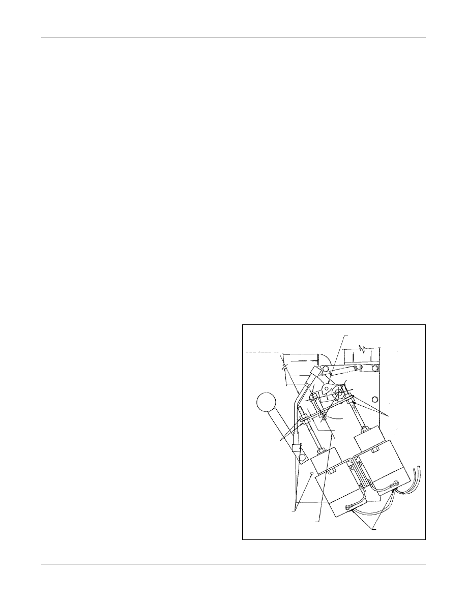
Fig. 4 - Engine Run-Stop Governor Control
V-71 AND V-92 SERIES ENGINES
Adjust the gap by loosening the four (4) Go venor Solenoid
Mounting Bolts (Fig. 3), slide the Solenoid to the desired
position and re-torque the mounting bolts. Re-check the gap
and repeat the adjustment if necessary . After the check is
completed return the mode selector switch to the AUTO-
MATIC position.
WARNING:
DO NOT lea ve the MODE SELECT OR
switch in the MANU AL R UN position
during AUTOMATIC operation. (The
controller will be una ble to stop the
engine and O VERHEAT D AMAGE
WILL RESULT)
When the adjustments have been completed, start the engine
from the ENGINE CONTROLLER (AEC), using the MAN-
UAL mode. Verify the Gap Dimension again, then stop the
engine. Return all controls to the AUTOMATIC mode.
INLINE 71 SERIES (Ref. Fig. 4, Pg. 42-B)
STEP 1. With the mounting brack et, torsion spring (under
levers), upper and lo wer le vers in place, adjust the upper
lever as follows:
A. Insert a 1/
4
" bolt aproximately 21/
2
" long through hole
in upper lever so it extends down through locating hole
in the mounting bracket.
B. Remove rocker cover and manually hold the injector
control tube in the
NO
fuel position.
C. Push both levers down on shaft until they bottom, then
raise them 1/
8
" to provide free movement of the lower
lever.
D. After v erifying all conditions of steps A, B and C,
torque the clamping bolt in the upper lever to 7-9 lb. ft.
STEP 2. Adjust rod length so there is a def inite tightness
when the manual operating handle passes through the
straight outw ard position near the end of its CCW tra
vel.
(Tightness equals zero clearance shortened by tw o turns of
one rod end).
STEP 3. Position the solenoids so the centerline of the slide
pin equally di vides the arc created by the mo vement of the
lever pin. See diagram (Fig. 4).
STEP 4. Adjust equalizer bar as follows:
A. Check to be sure the jam nuts on each solenoid shaft
are loose.
B. Rotate manual operating handle CCW to the lock ed
position for manual operation.
C. Remove small scre ws from rear co vers of both sole-
noids and remove covers.
D. Manually, push on one of the solenoid shafts until the
contacts at the rear of that solenoid open at least 1/
32
"
(0.79 mm). While holding the solenoid shaft in this
position, tighten the jam nuts against the equalizer bar
on the plunder at a position that pro
vides a 0.020"
(0.51 mm) clearance at gap "A".
E. Manually, hold both solenoid shafts as described in 4D
above and tighten the tw o remaining jam nuts against
the equalizer bar without causing it to be f
orced in
either direction. The 0.020" (0.51 mm) c
learance
should be maintained at gap "A".
STEP 5. Operate mechanism both electrically and manually
to verify smooth and trouble free operation. During electrical
check, verify that rear contacts on both solenoids open at
least 1/
32
". (0.79 MM) Readjust equalizer bar as required.
STEP 6. Reinstall covers on solenoids.
SEE STEP #2
SEE STEP #3
SEE STEP #4
SEE STEP #1
SEE STEP #5
SEE STEP #5
GAP "A"
SEE STEP #5