INDIAN RAILWAYS MAINTENANCE MANUAL FOR DIESEL LOCOMOTIVES - PART 41
 

  Index      Engines     INDIAN RAILWAYS MAINTENANCE MANUAL FOR DIESEL LOCOMOTIVES 2013 year


Search            


Content   ..  39  40  41  42   ..


INDIAN RAILWAYS MAINTENANCE MANUAL FOR DIESEL LOCOMOTIVES - PART 41


Document No: 

Chapter –8  Fuel & Lubricants 


Version No: 1.0-d0 

Date Issued: dd/mm/yyyy 

Document Title: MANUAL MAINTENANCE FOR  DIESEL LOCOMOTIVES 
 

Revised 2013 

Printed: 2015/03/08 

Page 156 of 303


companies for storage of large quantities of fuel in their distribution depots). 
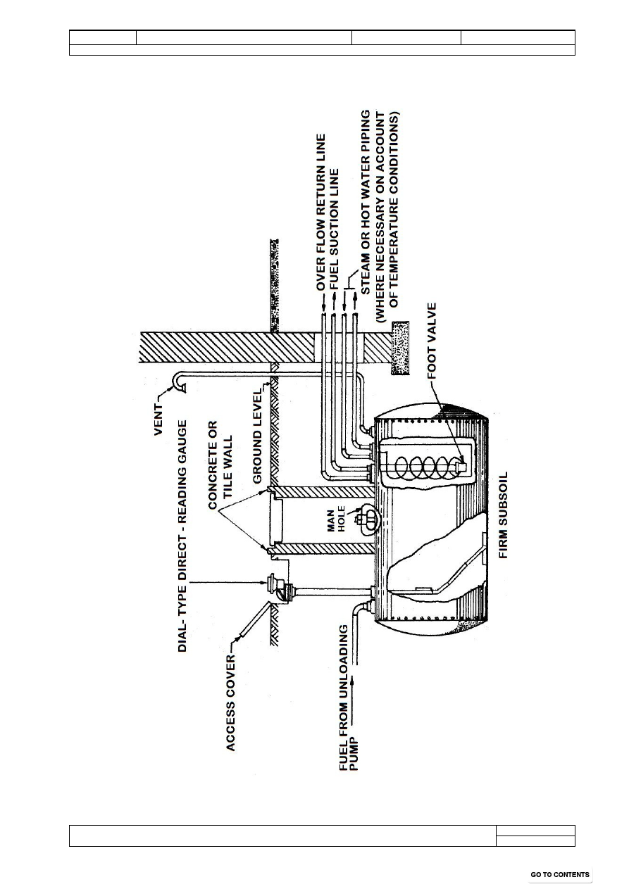
Figures 8.2 and 8.3 show respectively typical underground fuel tank with 
connections and vertical outdoor stand pipe type tank installation. 


Figures 8.2   

Ch-8 

Draft

Document No: 

Chapter –8  Fuel & Lubricants 


Version No: 1.0-d0 

Date Issued: dd/mm/yyyy 

Document Title: MANUAL MAINTENANCE FOR  DIESEL LOCOMOTIVES 
 

Revised 2013 

Printed: 2015/03/08 

Page 157 of 303


Figures 8.3

Home 

Ch-8 

Draft

Document No: 

Chapter –8  Fuel & Lubricants 


Version No: 1.0-d0 

Date Issued: dd/mm/yyyy 

Document Title: MANUAL MAINTENANCE FOR  DIESEL LOCOMOTIVES 
 

Revised 2013 

Printed: 2015/03/08 

Page 158 of 303


8.4.3.3  The cylindrical tanks, of the type most commonly used in RCDs, should be 

provided with a fall of about 4-5 cm per meter length from the outlet end (fuel 
discharge end) towards a drain cock provided at the rear. This will enable the 
water and sediment to gravitate towards the drain cock from where sludge can 
be taken out before the tank is refilled with fresh fuel. 


8.4.3.4  The cylindrical storage tanks should be mounted on a brick cradle, which could 

alternatively be of steel or concrete. The installation may be either in a shed or 
in an open enclosure. If the tank is to be underground, it may be housed in a 
specially constructed cradle of concrete. It is, however, important that the tank 
should be protected by a heavy coating of asphaltic bitumen or a bituminous 
compound to prevent corrosion by moisture and seepage water. 


8.4.3.5  It is also good practice to provide a high level day-tank (with gravity feed) 

holding approximately one day’s fuel consumption so that in case of failure of 
the regular fuelling arrangements, no difficulty is experienced in fueling of the 
locos. 


8.4.4 

Water Drain off Sump and Valve:  A small sump at the bottom of vertical type 
tank should be provided with proper pipe and valve connections to draw off 
accumulation of water. 


8.4.5 

Location of Tank Outlet: The outlet for fuel discharge from the tank should be so 
located that the fuel oil will be drawn off at a level of about 20cm above bottom of 
the tank thus allowing space for collection of water and sludge. 


8.4.6 

Internal Checks Valves: An internal check (safety) valve in the outlet pipe should 
be provided which will automatically close in case of a fire. 


8.4.7 

Vents: Mushroom, goose neck or ‘T’ type vents are used. They should be screened 
to prevent entrance of birds and insects into the tank. If the tank is under cover, the 
vents should terminate in the open atmosphere. The vent pipe should be of ample 
size and its end should be protected with a flame  arrestor and so arranged as to 
prevent rain from entering or draining into the tank. 


8.4.8 

Level indicators: Several types of level indicators are used. They should cover the 
full height of the tank and should be of a design that will permit accurate 
determination of the amount of fuel in the tank at any time. 


8.4.9 

Painting of the Tanks: 


8.4.9.1  In preparation for painting, the steel tanks after fabrication should be immersed in 

hot phosphoric acid bath to ensure complete removal of mill scale and rust. 
These should then be painted with a red lead of zinc chromate primer. After 
erection at the site, the tank should receive a second coat of primer followed by 
the finishing coat. Aluminum or   white paint is preferable since it reflects, 
rather than absorbs heat from the sun and thus tends to keep the stored fuel oil at 
a lower temperature.  


Draft

Document No: 

Chapter –8  Fuel & Lubricants 


Version No: 1.0-d0 

Date Issued: dd/mm/yyyy 

Document Title: MANUAL MAINTENANCE FOR  DIESEL LOCOMOTIVES 
 

Revised 2013 

Printed: 2015/03/08 

Page 159 of 303


8.4.9.2  The inner side of the bottom plate should be given a bituminous coating prior to 

welding. There is no need to paint the interior of the fuel oil tank. 


8.4.10 

Drawing out of impurities:  Sludge gets collected in the HSD Tank –  both in 
underground and above ground level tanks, in spite of all precautionary measures 
including periodical draining. Presence of silica in the ash analysis gives an 
indication that dust invariably finds its way into the tank in course of time. Presence 
of iron is perhaps due to corrosion products from the plates. It is however, difficult 
to estimate the rate of collection of sludge in any tank since lot of variables are 
involved. The cleaning and painting of the storage tank should be done after 5 years 
by the oil company. However, inspection of storage tanks will be done jointly by 
the representatives of the Railways and the Oil company every 4 years from the 
date of installation/last cleaning. If conditions warrant, the tanks will be cleaned and 
painting will be done after 4 years. During cleaning of the storage tanks, the 
accumulated sludge is to be collected and disposed off as stipulated in para 3.4 of 
Rly Board’s JPO of Feb’10.  This will also give a chance to attend to any damages 
to gusset plates of the tanks and an inspection for leaks can, in addition, be made. 
For this purpose a hand pump may be provided, taking suction through a line 
reaching down nearly to the bottom of the tank at its lower end. In the absence of 
this arrangement, ordinary drain cock for de-sludging may be provided.  


8.4.11 

Fuel feed pipes: 


8.4.11.1  Fuel supplies are pumped into the tank through the fuel feed pipe going down 

about 5 to 7 cm into the tank from the top. The filling connection at the top 
should be protected by a dust cap. 


8.4.11.2  The essential fittings on fuel tanks are – 

a.  Vent pipes 
b.  Man holes to facilitate interior cleaning and inspection 
c.  Weather proof filler cap and suction valves 
d.  Sludge drainage cocks and pumps. 
e.  Fuel level indicators 
f.  Suitable pumps  along with filters and strainers, both for the incoming 

supply as well as the outgoing supply from the storage tanks 


8.5 

Fuel Oil pumping Facilities  
 

8.5.1 

  Selection of Pump: 


8.5.1.1  Electric motor driven pumps of the centrifugal, the rotary displacement or the 

reciprocating piston type are usually employed. The centrifugal pumps with 
self-priming arrangement may be used where there is a flooded suction or very 
little suction lift. Rotary displacement type pumps are ideally suited to locations 
where appreciable suction lift is involved. These pumps must be equipped with 
relief valve and by-pass arrangement to prevent development of excessive 
pressure when outlets are closed. A check valve should also be placed in the 
pump discharge line, before the shut off valve, to prevent back flow of the oil 
from the tank when the pump is shut down.  


8.5.1.2  In addition to Electric Pump, a diesel pump as stand-by should also be provided. 

Home 

Ch-8 

Draft


Content   ..  39  40  41  42   ..