Kawasaki Diesel MULE 4010 TRANS 4x4 (KAF950G9). Manual - part 135


  Index      Engines     Kawasaki Diesel MULE 4010 TRANS 4x4 (KAF950G9) - service manual


Search            


Content   ..  133  134  135  136   ..


Kawasaki Diesel MULE 4010 TRANS 4x4 (KAF950G9). Manual - part 135


18-18 APPENDIX

Cable, Wire, and Hose Routing
APPENDIX 18-19

Cable, Wire, and Hose Routing

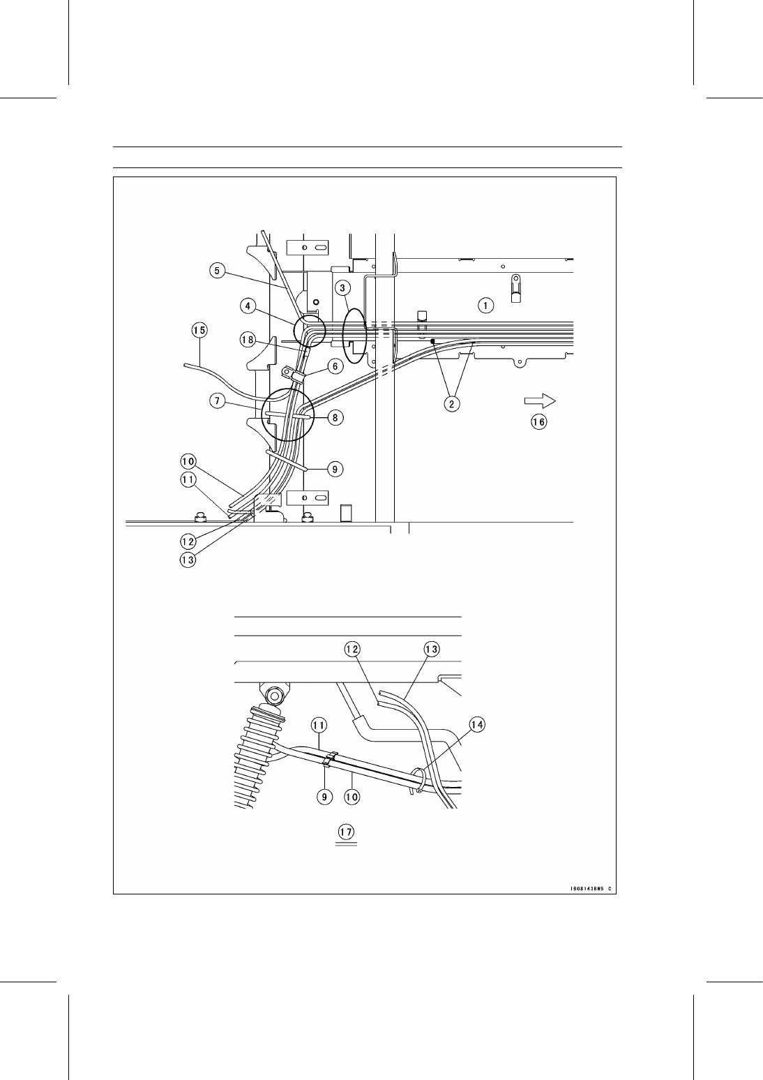
1. Run the cables straight to front.
2. Trim
3. Run the cables under the main harness and fuel hose.
4. Run the cables on the damper of right rear brake pipe.
5. Throttle Cable
6. Fix the differential shift cable, 2WD/4WD shift cable and speedometer cable with the clamp.
7. Be sure that there is clearance between the cables and the shaft drive.
8. Fix the transmission shift cable and hi/low shift cable with the band.
9. Clamp

10. Differential Shift Cable: Keep 25 mm (0.98 in.) or more clearance between the rear shock

absorber and differential shift cable. Run the cable on the outside of right rear brake hose.

11. 2WD/4WD Shift Cable: Keep 25 mm (0.98 in.) or more clearance between the rear shock

absorber and 2WD/4WD shift cable. Run the cable on the outside of right rear brake hose.

12. Transmission Shift Cable
13. Hi/Low Shift Cable
14. Band
15. Speedometer Cable
16. Front
17. Right Side View of Rear Area
18. Set the white mark between center bracket and clamp.

18-20 APPENDIX

Cable, Wire, and Hose Routing

1. Run the speed sensor lead through inside

of the 2WD/4WD shift cable and differen-
tial shift cable.

2. Band
3. Tail/Brake Light Lead
4. 80 mm (3.15 in.)
5. Clamp
6. Band
7. Neutral Switch Lead
8. Detail A
9. Fill up lithium grease (NLGI Grade No.2).

10. Band

11. Neutral Switch Lead

12. 80 mm (3.15 in.)
13. Tape the tube at both ends.
14. 490

∼ 500 mm (19.3 ∼ 19.7 in.)

15. Front
16. View from Top
17. Upper
18. Right
19. Detail B
20. Detail C

APPENDIX 18-21

Cable, Wire, and Hose Routing

1. Floor Center Panel
2. Trim
3. Run the main harness under the leads.
4. Main Harness
5. Alternator Lead (Brown)
6. Alternator Cable (Red)
7. Starter Motor Lead
8. Battery (–) Cable (to Engine Ground)
9. Battery (+) Cable (to Starter Motor)

10. Align the white tape of the harness with

this clamp.

11. Band

12. Parking Brake Switch Lead
13. Starter Circuit Relay
14. Preheating Timer
15. Radiator Fan Relay
16. Glow Plug Relay
17. Run the branch of harness on right side

of clamp.

18. Run the battery (+) (–) cables on the rub-

ber damper for the left rear brake line.

19. Front
20. Upper
21. Inside


Content   ..  133  134  135  136   ..