Kawasaki Diesel MULE 4010 TRANS 4x4 (KAF950G9). Manual - part 129
 

  Index      Engines     Kawasaki Diesel MULE 4010 TRANS 4x4 (KAF950G9) - service manual


Search            


Content   ..  127  128  129  130   ..


Kawasaki Diesel MULE 4010 TRANS 4x4 (KAF950G9). Manual - part 129


17-62 ELECTRICAL SYSTEM

Switches and Sensors

Brake Light Switch Inspection

Refer to the Brake Light Switch Inspection in the Periodic
Maintenance chapter.

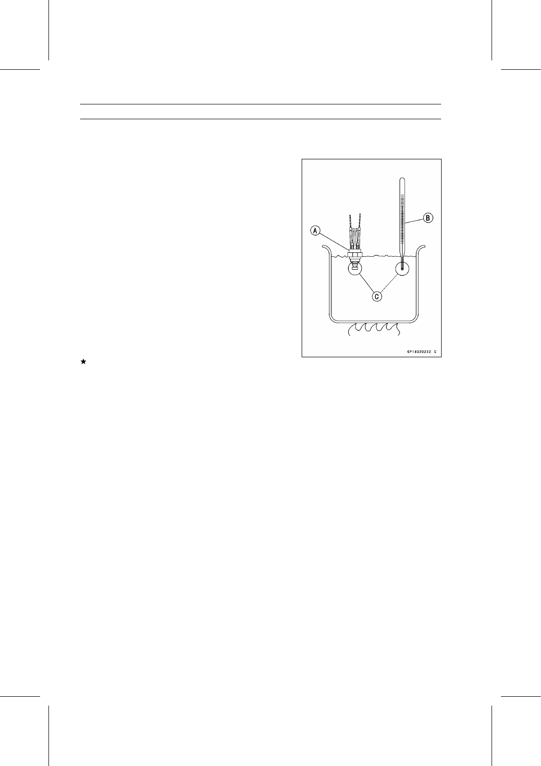
Radiator Fan Switch Inspection

Remove the radiator fan switch (see Radiator Fan Switch
Removal in the Cooling System chapter).

Suspend the fan switch [A] in a container of coolant so that
the temperature sensing projection and threaded portion
are submerged.

Suspend an accurate thermometer [B] in the coolant, so
that the sensitive portions [C] are located in almost the
same depth.

NOTE

The switch and thermometer must not touch the con-
tainer sides or bottom.

Place the container over a source of heat and gradu-
ally raise the temperature of the coolant while stirring the
coolant gently.

Using the hand tester, measure the internal resistance
of the switch across the terminals at the temperatures
shown in the table.

Special Tool - Hand Tester: 57001-1394

If the hand tester does not show the specified values, re-
place the switch.

Radiator Fan Switch Resistance

Rising Temperature:

From OFF to ON at 86

∼ 90°C (187 ∼ 194°F)

Falling Temperature:

From ON to OFF at 81

∼ 85°C (178 ∼ 185°F)

ON: Less than 0.5 Ω
OFF: More than 1 MΩ

ELECTRICAL SYSTEM 17-63

Switches and Sensors

Coolant Temperature Switch Inspection

Remove the coolant temperature switch (see Coolant
Temperature Switch Removal in the Cooling System
chapter).

Suspend the switch [A] in a container of coolant so that
the temperature sensing projection and threaded portion
are submerged.

Suspend an accurate thermometer [B] in the coolant, so
that the sensitive portions [C] are located in almost in the
same depth.

NOTE

The switch and thermometer must not touch the con-
tainer sides or bottom.

Place the container over a source of heat and gradu-
ally raise the temperature of the coolant while stirring the
coolant gently.

Using the hand tester, measure the internal resistance
of the switch across the connector and the body at the
temperatures shown in the table.

Special Tool - Hand Tester: 57001-1394

If the hand tester does not show the specified values, re-
place the switch.

Coolant Temperature Switch Resistance

Rising Temperature:

From OFF to ON at 112

∼ 118°C (234 ∼ 244°F)

Falling Temperature:

From ON to OFF within 10°C (50°F)
of “ON” temperature

ON: Less than 0.5 Ω
OFF: More than 1 MΩ

17-64 ELECTRICAL SYSTEM

Switches and Sensors

Switch Inspection

Using a hand tester, check to see that only the con-
nections shown in the table have continuity (about zero
ohms).

Special Tool - Hand Tester: 57001-1394

For the main switch, light switch, brake light switch, park-
ing brake light switch, and neutral switch, refer to the ta-
bles in the Wiring Diagram.
If the switch has an open or short, repair it or replace it
with a new one.

Horn Switch Connections

Oil Pressure Switch Connections*

*: Engine lubrication system is in good condition.

Reverse Light Switch Connections (EUR Model)

Speed Sensor Removal

NOTICE

Never drop the speed sensor, especially on a hard
surface. Such a shock to the sensor can damage it.

Drain the transmission oil (see Transmission Oil Change
in the Periodic Maintenance chapter).

Disconnect the speed sensor lead connector [A].

Remove:

Bolt [B]
Speed Sensor [C]

ELECTRICAL SYSTEM 17-65

Switches and Sensors

Speed Sensor Installation

Replace the O-ring [A] with a new one.

Apply transmission oil to the O-ring.

Tighten

Torque - Speed Senor Bolt: 8.8 N·m (0.90 kgf·m, 78 in·lb)

Speed Sensor Inspection

Remove the speed sensor (see Speed Sensor Removal).

Connect the speed sensor connector [A] with the battery
[B], 10 kΩ resistor [C] and hand tester [D] as shown in the
figure.

Set the tester to the DC 25 V range.

Special Tool - Hand Tester: 57001-1394

Trace [A] each side of the speed sensor surface with the
screwdriver.

Then the tester indicator should flick [B].
If the tester indicator does not flick, replace the speed
sensor.


Content   ..  127  128  129  130   ..