Kawasaki Diesel MULE 4010 TRANS 4x4 (KAF950G9). Manual - part 128
 

  Index      Engines     Kawasaki Diesel MULE 4010 TRANS 4x4 (KAF950G9) - service manual


Search            


Content   ..  126  127  128  129   ..


Kawasaki Diesel MULE 4010 TRANS 4x4 (KAF950G9). Manual - part 128


17-58 ELECTRICAL SYSTEM

Lighting System

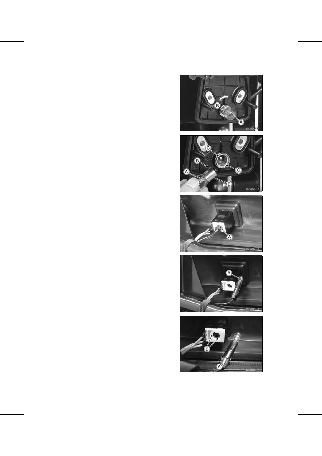
Push and turn the bulb [A] counterclockwise [B] and re-
move it.

NOTICE

Do not use bulbs rated for greater wattage than the
specified value.

Insert the new bulb [A] by aligning its upper and lower pins
[B] with the upper and lower grooves [C] in the socket, and
turn the bulb clockwise.

Turn the bulb about 15°.

Install the tail/brake light lens.

Be careful not to overtighten the lens mounting screws.

Light Switch Bulb Replacement

Remove the front cargo compartment (see Front Cargo
Compartment Removal in the Frame chapter).

Turn the socket [A] counterclockwise, and pull it with the
bulb.

Pull the bulb [A] out of the socket.

NOTICE

Do not turn the bulb. Pull the bulb out to prevent
damage to the bulb.
Do not use bulb rated for greater wattage than the
specified value.

Insert the new bulb in the socket.

Align the projections [A] of the socket with the recesses
[B] in the switch body, and turn the socket clockwise.

ELECTRICAL SYSTEM 17-59

Lighting System

Indicator Light Bulb Replacement

Oil Pressure Warning Indicator Light [A]
Coolant Temperature Warning Indicator Light [B]
Parking Brake Indicator Light [C]
Glow Plug Light [D]

Remove:

Light Assembly [A]
Lens [B]

Roll the rubber [A] up and pull the bulb [B] out of the
socket.

NOTICE

Do not turn the bulb. Pull the bulb out to prevent
damage to the bulb.
Do not use bulb rated for greater wattage than the
specified value.

Install:

New Bulb
Lens [A]
Light Assembly [B]

Speedometer Illumination Bulb Replacement

Remove the front cargo compartment (see Front Cargo
Compartment Removal in the Frame chapter).

Pull the socket [A] with the bulb from the speedometer.

17-60 ELECTRICAL SYSTEM

Lighting System

Pull the bulb [A] out of the socket [B].

NOTICE

Do not turn the bulb. Pull the bulb out to prevent
damage to the bulb.
Do not use bulb rated for greater wattage than the
specified value.

Insert the new bulb in the socket [A].

Install the socket into the speedometer [B].

Headlight Removal

Remove:

Front Cover (see Front Cover Removal in the Frame
chapter)
Bolts [A] (KAF950F9

∼ FB)

Screws [A] (KAF950FC

∼)

Screws [B]

Headlight Installation

Check that the clip-nuts [A] are in place as shown in the
figure.

For the KAF950F9

∼ FB, tighten the bolts and screws.

For the KAF950FC, tighten the screws.

Install the front cover (see Front Cover Installation in the
Frame chapter).

Reverse Light Switch Installation (EUR Model)

Put the transmission shift lever in the REVERSE position.

Install the reverse light switch bracket [A] on the reverse
shift lever so that the switch rod [B] contacts the boss [C]
and the clearance is 1

∼ 2 mm (0.04 ∼ 0.08 in.) [E].

Tighten the shift shaft lever clamp bolt [D] securely.

ELECTRICAL SYSTEM 17-61

Lighting System

Lighting System Circuit

1. Speedometer Illumination
2. Oil Pressure Warning Indicator Light
3. Coolant Temperature Warning Indicator

Light

4. Parking Brake Indicator Light
5. Light Switch Indicator Light
6. Light Switch
7. Main Switch
8. Headlights
9. Brake Light Switch

10. Coolant Temperature Switch

11. Parking Brake Light Switch

12. Oil Pressure Switch
13. EPS Fuse 7.5 A
14. EPS Warning Indicator Light (LED)
15. EPS ECU
16. Reverse Light Switch (EUR Model)
17. Reverse Light (EUR Model)
18. Tail/Brake Lights
19. Battery
20. Main Fuse 30 A
21. Fuse Box 2


Content   ..  126  127  128  129   ..