Kawasaki Diesel MULE 4010 TRANS 4x4 (KAF950G9). Manual - part 126
 

  Index      Engines     Kawasaki Diesel MULE 4010 TRANS 4x4 (KAF950G9) - service manual


Search            


Content   ..  124  125  126  127   ..


Kawasaki Diesel MULE 4010 TRANS 4x4 (KAF950G9). Manual - part 126


17-50 ELECTRICAL SYSTEM

Fuel Cut Solenoid

Fuel Cut Solenoid

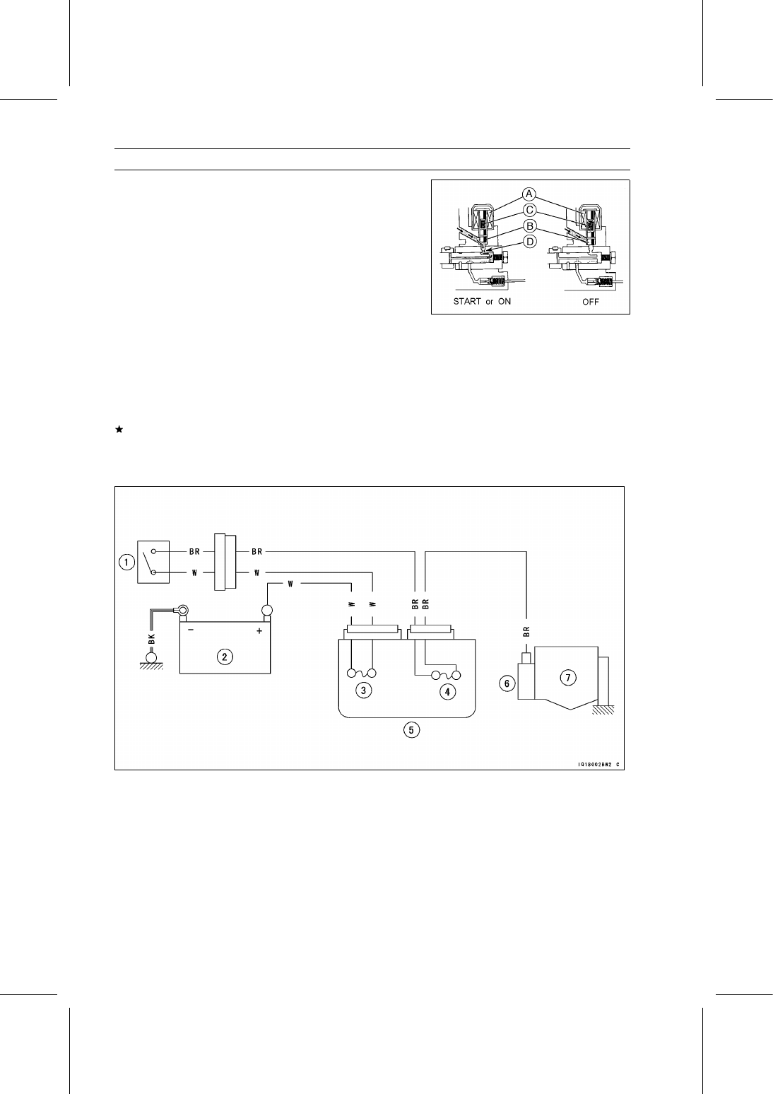
The fuel cut solenoid [A] is in the fuel injection pump.
When the main switch is turned to the “START” position,

the fuel solenoid is energized and the solenoid valve [B]
lifts against the spring [C] and opens the fill port [D] to the
pressure chamber.

When the switch is returned to the “ON” position, after the

engine has started, the current flows through a resistor to
the solenoid, reducing the current slightly but maintaining
enough energy to hold the valve open.

Turning the main switch to the “OFF” position shuts off the

current to the solenoid. With no current to hold the valve,
the spring forces the valve to close the fill port, thus shutting
off the fuel supply and the engine.

Fuel Cut Solenoid Inspection

When the main switch is turned ON, check that the fuel
cut solenoid makes a clicking sound (operating sound).
If the fuel injection pump does not click, replace it, or con-
sult a reliable fuel injection pump repair shop (ex. Denso
Service Station).

Fuel Cut Solenoid Circuit

1. Main Switch
2. Battery
3. Main Fuse 30 A
4. Preheating Timer Fuse 5 A
5. Fuse Box 2
6. Fuel Cut Solenoid
7. Fuel Injection Pump

ELECTRICAL SYSTEM 17-51

Radiator Fan

Radiator Fan Circuit Inspection

Remove the front cargo compartment (see Front Cargo
Compartment Removal in the Frame chapter).

Disconnect the leads from the radiator fan switch.

Using an auxiliary lead [A], connect the radiator fan switch
leads.
If the radiator fan rotates, inspect the radiator fan switch.
If the radiator fan does not rotate, inspect the following.

Wiring and Connectors
Radiator Fan Breaker (see Radiator Fan Breaker In-
spection)
Radiator Fan Motor (see Radiator Fan Motor Inspection)
Radiator Fan Relay (see Radiator Fan Relay Inspection)

Radiator Fan Motor Inspection

Disconnect the fan motor lead connector [A] from the har-
ness.

Using two auxiliary leads, supply battery power to the fan
motor.
If the fan does not rotate at this time, the fan motor is
defective and must be replaced.

Radiator Fan Motor Leads

Red

: Battery (+)

Black

: Battery (–)

Radiator Fan Breaker Inspection

Tilt up the front seat.

Remove:

Battery Cables (see Battery Removal)
Radiator Fan Breaker [A]

Inspect the breaker for operation.

Connect:

12 V Battery [A]
0.3 Ω Resistance [B]
Radiator Fan Breaker [C]
Switch [D]

If the circuit in the breaker will not open within 60 seconds,
replace the breaker.

17-52 ELECTRICAL SYSTEM

Radiator Fan

Radiator Fan Relay Inspection

Remove:

Front Seat Lower Cover Left (see Starter Relay Inspec-
tion)
Radiator Fan Relay Lead Connector [A]
Radiator Fan Relay [B]

Connect the hand tester [A] and 12 V battery [B] to the
radiator fan relay [C] as shown in the figure.

Special Tool - Hand Tester: 57001-1394

If the relay does not work as specified, the relay is defec-
tive. Replace the relay.

Testing Relay

Hand Tester Range: × 1 Ω
Criteria:

When battery is connected → 0 Ω
When battery is disconnected → ∞ Ω

Relay Coil Terminals [1] and [2]
Relay Switch Terminals [3] and [4]

ELECTRICAL SYSTEM 17-53

Radiator Fan

Radiator Fan Circuit

1. Radiator Fan Relay
2. Radiator Fan Switch
3. Radiator Fan
4. Battery
5. Radiator Fan Breaker


Content   ..  124  125  126  127   ..