Kawasaki Diesel MULE 4010 TRANS 4x4 (KAF950G9). Manual - part 124
 

  Index      Engines     Kawasaki Diesel MULE 4010 TRANS 4x4 (KAF950G9) - service manual


Search            


Content   ..  122  123  124  125   ..


Kawasaki Diesel MULE 4010 TRANS 4x4 (KAF950G9). Manual - part 124


17-42 ELECTRICAL SYSTEM

Electric Starter System

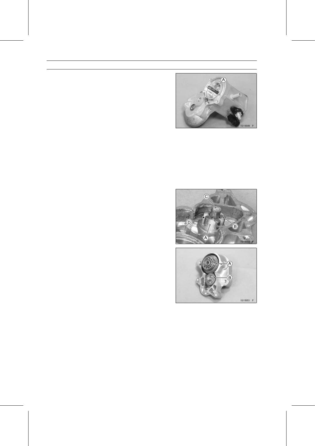
Remove the return spring [A].

Starter Motor Assembly

Apply grease to the following parts.

Retainer and Rollers
Starter Clutch
Steel Ball
Return Spring
Armature Bearing

Grease - Denso No. 50 Grease or Equivalent (Esso Beacon

325)

Install the retainer [A] and rollers [B] on the drive end
cover shaft [C].

Face the opening side [D] of the retainer to the magnetic
switch assy.

Install:

Starter Clutch [A]
Idle Gear [B]

Install:

Steel Ball
Return Spring
Drive End Cover and Screws

ELECTRICAL SYSTEM 17-43

Electric Starter System

Install the positive brushes [A] on the brush plate [B] with
needle nose pliers.

Pull the springs [C] and brushes, and hold the brushes
with the springs.

Install the armature.

Install:

End Cover [A]
End Cover Screws [B] and O-rings

Tighten:

Torque - Starter Motor End Cover Screws: 1.5 N·m (0.15

kgf·m, 13 in·lb)

Install the yoke [A] on the magnetic switch [B].

Tighten:

Torque - Starter Motor Through Bolts: 9.3 N·m (0.95 kgf·m,

82 in·lb)

Install the field coil cable and tighten the nut securely.

Carbon Brush Inspection

Measure the carbon brush length [A].
If the brush length is less than the service limit, replace
the brush assembly.

Carbon Brush Length

Standard:

15.5 mm (0.61 in.)

Service Limit:

11.0 mm (0.43 in.)

Yoke Inspection

Measure the resistance between the carbon brush and
the wire terminal [A].

Special Tool - Hand Tester: 57001-1394

If there is not close to 0 Ω, the field coils have an open.
Replace the yoke.

Measure the resistance between the carbon brush and
the yoke body [B].
If there is any reading, the yoke has a short. Replace the
yoke.

17-44 ELECTRICAL SYSTEM

Electric Starter System

Brush Plate Inspection

Measure the resistance between the carbon brush and
the brush plate [A].

Special Tool - Hand Tester: 57001-1394

If there is not close to 0 Ω, the brush plate has an open.
Replace the brush plate.

Measure the resistance between the brush plate and the
(+) brush holder [B].
If there is any reading, the brush plate has a short. Re-
place the brush plate.

Commutator Cleaning/Inspection

Smooth the commutator surface [A] if necessary with fine
emery cloth [B], and clean out the grooves.

Measure the diameter [A] of the commutator [B].
Replace the starter motor with a new one if the commu-
tator diameter is less than the service limit.

Commutator Diameter

Standard:

30 mm (1.18 in.)

Service Limit:

29 mm (1.14 in.)

Armature Inspection

Using the × 1 Ω range of the hand tester, measure the
resistance between any two commutator segments [A].

Special Tool - Hand Tester: 57001-1394

If there is a high resistance or no reading (∞) between
any two segments, a winding is open. Replace the starter
motor.

Using the highest range of the hand tester, measure the
resistance between the segments and the shaft [B].
If there is any reading at all, the armature has a short.
Replace the starter motor.

NOTE

Even if the foregoing checks show the armature to be
good, it may be defective in some manner not readily
detectable with the hand tester. If all other starter motor
and starter motor circuit components check good, but
the starter motor still does not turn over or only turns
over weakly, replace the starter motor with a new one.

ELECTRICAL SYSTEM 17-45

Electric Starter System

Pinion Gear Inspection

Turn the pinion gear by hand. It should turn clockwise
freely [A], but should not turn freely counterclockwise [B].
If the pinion gear does not operate as it should or if there
is any worn or damaged part, replace it.

Starter Switch Inspection

Connect a 12 V battery to the starter switch [A] as shown
in the figure.

Connect the battery negative (–) cable [B] first and then
the positive lead to the terminal in the connector [C].
If the switch does not work as specified, the switch is de-
fective. Replace the starter switch.

Testing Switch

Criteria: When battery is connected →

Pinion gear must move outward quickly.

When battery is disconnected →

Pinion gear must return quickly.

Starter Circuit Relay Inspection

Remove:

Mounting Rivets [A]
Screws [B]
Front Seat Lower Cover Left [C]

Remove:

Starter Circuit Relay Connector [A]
Starter Circuit Relay [B]


Content   ..  122  123  124  125   ..