Kawasaki Diesel MULE 4010 TRANS 4x4 (KAF950G9). Manual - part 123
 

  Index      Engines     Kawasaki Diesel MULE 4010 TRANS 4x4 (KAF950G9) - service manual


Search            


Content   ..  121  122  123  124   ..


Kawasaki Diesel MULE 4010 TRANS 4x4 (KAF950G9). Manual - part 123


17-38 ELECTRICAL SYSTEM

Alternator

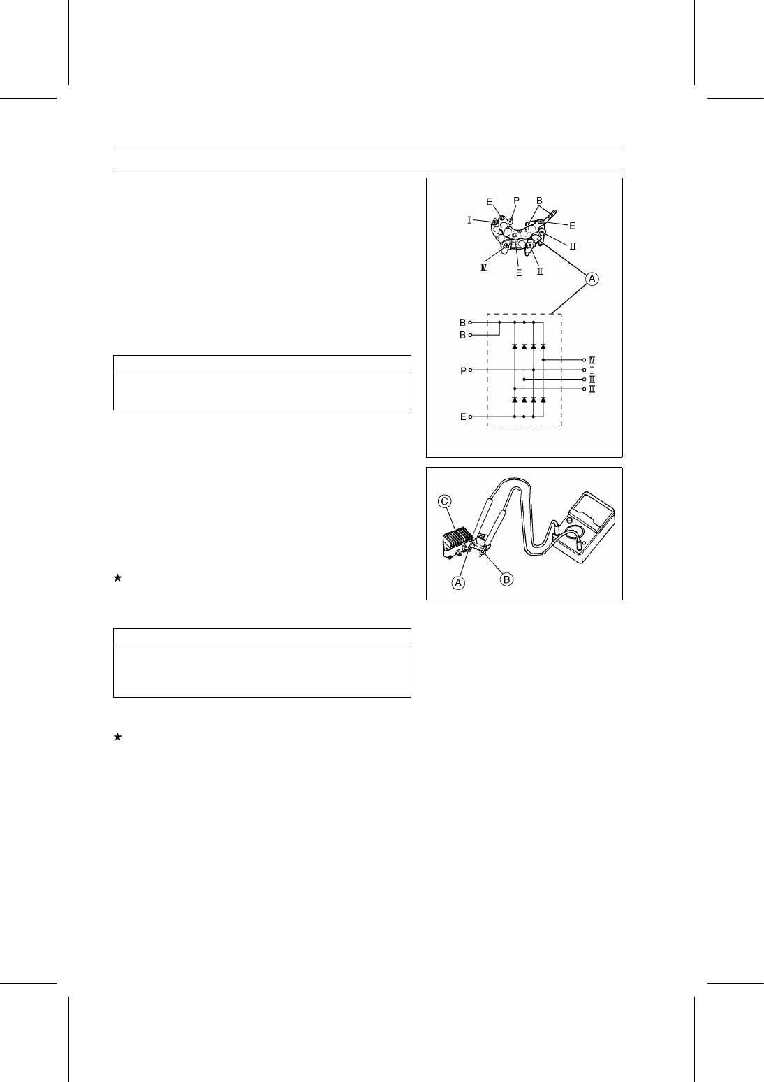
Rectifier Inspection

Set the hand tester to the 1 kΩ range.

Zero the hand tester, and connect it to each terminal to
check the resistance in both directions.

The resistance should be low in one direction and more
than ten times as much in the other direction. If the rec-
tifier [A] shows low or high in both directions, the rectifier
is defective and the rectifier must be replaced.

NOTE

The actual meter reading varies with the meter used
and the individual rectifier, but, generally speaking, the
lower reading should be from zero to one half the scale.

NOTICE

If a megger or a meter with a large-capacity battery
is used, the rectifier will be damaged.

Regulator Inspection

Set the hand tester to the 1 kΩ range.

Special Tool - Hand Tester: 57001-1394

Check the resistance between F [A] and B [B] terminals
in both directions.

The resistance should be low in one direction and more
than ten times as much in the other direction.
If the reading shows low or high in both directions, the
regulator [C] is defective and must be replaced.

Alternator Ball Bearing Inspection

NOTICE

Do not disassemble the alternator for bearing in-
spection since disassembling the alternator dam-
ages the bearings.

Turn the alternator rotor shaft back and forth while check-
ing for play, roughness or binding of bearings.
If bearing play, roughness, or binding is found, disassem-
ble the alternator and replace the bearings.

ELECTRICAL SYSTEM 17-39

Alternator

Alternator Circuit

1. Main Switch
2. Battery
3. Fusible Link 50 A
4. Load
5. Alternator
6. Stator Coil
7. Rotor
8. Rectifier
9. Regulator

10. Main Fuse 30 A

11. Fuse Box 2

17-40 ELECTRICAL SYSTEM

Electric Starter System

Starter Motor Removal

Tilt up the cargo bed.

Remove:

Starter Motor Lead Connector [A]
Starter Motor Cable [B]
Starter Motor Mounting Bolts [C]
Starter Motor [D]

Starter Motor Installation

Clean the mating surface [A] of the starter motor and the
end plate where the starter motor is grounded.

Apply liquid gasket [A] to the mating surface as shown in
the figure.

Sealant - Three Bond: 1207F

Install the starter motor and tighten the mounting bolts.

Torque - Starter Motor Mounting Bolts: 39 N·m (4.0 kgf·m,

29 ft·lb)

Starter Motor Disassembly

Remove:

Field Coil Cable Nut [A]
Field Coil Cable [B]

Remove:

Starter Motor Through Bolts [A]
Yoke [B]

ELECTRICAL SYSTEM 17-41

Electric Starter System

Remove:

End Cover Screws [A] and O-rings
End Cover [B]

Remove:

Armature [A]
Positive Brushes [B]
Brush Plate [C]

Remove:

Drive End Cover Screws [A]
Drive End Cover [B]

Remove:

Starter Clutch [A]
Idle Gear [B]
Steel Ball [C]

Remove:

Retainer [A]
Rollers [B]


Content   ..  121  122  123  124   ..