Kawasaki Diesel MULE 4010 TRANS 4x4 (KAF950G9). Manual - part 121
 

  Index      Engines     Kawasaki Diesel MULE 4010 TRANS 4x4 (KAF950G9) - service manual


Search            


Content   ..  119  120  121  122   ..


Kawasaki Diesel MULE 4010 TRANS 4x4 (KAF950G9). Manual - part 121


17-30 ELECTRICAL SYSTEM

Battery

Ordinary Charging

DANGER

Batteries produce an explosive gas mixture of hy-
drogen and oxygen that can cause serious injury
and burns if ignited. Keep the battery away from
sparks and open flames during charging. When
using a battery charger, connect the battery to the
charger before turning on the charger. This proce-
dure prevents sparks at the battery terminals which
could ignite any battery gases.

NOTICE

Always remove the battery from the vehicle for
charging. If the battery is charged while still in-
stalled, battery electrolyte may spill and corrode
the frame or other parts of the vehicle.
Charging the battery at a rate higher than specified
may ruin the battery. Charging at a high rate causes
excess heat which can warp the plates and cause
internal shorting.
Higher-than-normal charging rates also cause the
plates to shed active material. Deposits will accu-
mulate, and can cause internal shorting.
If the temperature of the electrolyte rises above
45°C (113°F) during charging, reduce the charging
rate to lower the temperature, and increase charg-
ing time proportionately.

Remove the battery (see Battery Removal).

NOTE

Never attempt to charge a frozen battery.

Allow it to warm up to room temperature before charg-
ing.

Never leave a battery on a trickle charger longer than
48 hours. Serious damage to the battery will occur.

(Conventional Type Battery)

Charge the battery with a current of 1 to 1.5 amps until the
specific gravity rises to 1.250 and temperature reaches
15.5°C (60°F).

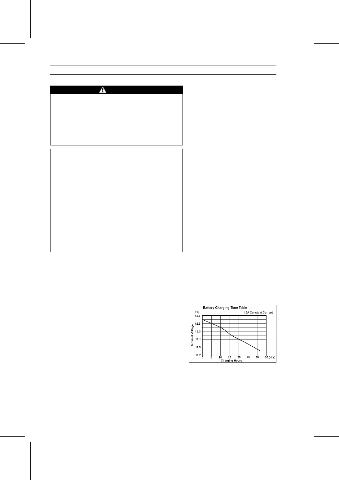
Refer to the Battery Charging Time Table for the charging.

ELECTRICAL SYSTEM 17-31

Battery

Check the electrolyte level after charging.
If the electrolyte level is low add water only after initial
activation.

WARNING

Electrolyte contains sulfuric acid which is harmful
to skin, eyes, and clothing.
Wear eye protection and rubber gloves.
If spillage occurs on body or clothing, rinse at once
with water for at least 15 minutes.

Turn the charger off or plug it, then disconnect it from the
battery.
If the battery condition indicates that it is not fully charged,
additional charging time is necessary.

(Sealed Type Battery)

Charge the battery according to the battery terminal volt-
age.

WARNING

This battery is sealed battery type. Never remove
seal sheet or cap [A] even at charging. Never add
water. Charge with current and time as stated be-
low.

Refer to the Battery Charging Time Table for the charging.

Battery Charging Time Table

at 27°C (80°F)

Charging Time to Full Charge

Battery

Voltage

State of

Charge

2 A

6 A

10 A

12.6 V

100%

Full Charge

12.4 V

75%

405 min.

135 min.

81 min.

12.2 V

50%

810 min.

270 min.

162 min.

12.0 V

25%

1 215 min.

405 min.

243 min.

11.8 V

0%

1 620 min.

540 min.

324 min.

Determine battery condition after charging.

Determine the condition of the battery 30 minutes after
completion of the charge by measuring the terminal volt-
age according to the table below.

Criteria

Judgement

12.6 V or higher

Good

12.0

∼ 12.6 V or lower

Charge insufficient → Recharge

12.0 V or lower

Unserviceable → Replace

Battery Testing Chart (Conventional Type Battery)

Once battery is in an adequate state of charge the fol-

lowing load test procedure will be valid. The load test is
undertaken to determine if the battery has adequate elec-
trical performance or if it has to be replaced.

Important: This procedure is valid only it the battery is at

or above the state of check specified in STEP 2.

17-32 ELECTRICAL SYSTEM

Battery

Battery Testing Chart

ELECTRICAL SYSTEM 17-33

Alternator

Alternator Removal

Remove:

Fan Belt Cover (see Cooling Fan Belt Inspection in the
Periodic Maintenance chapter)
Alternator Terminal Locknut [A]
Alternator Lead Connector [B]

Remove:

Alternator Adjusting Bracket Bolt [A]
Alternator Mounting Bolt [B]
Alternator [C]

Alternator Installation

Clean the alternator legs and alternator bracket where the
alternator is grounded.

Adjust the fan belt deflection (see Cooling Fan Belt In-
spection in the Periodic Maintenance chapter).

Tighten:

Torque - Alternator Adjusting Bracket Bolts: 20 N·m (2.0

kgf·m, 15 ft·lb)

Alternator Mounting Bolt: 39 N·m (4.0 kgf·m, 29

ft·lb)

Alternator Disassembly

Remove:

Terminal Nut [A]
Insulator [B]
End Cover Bolts [C]
End Cover [D]

Remove:

Brush Holder [A]
Regulator [B]
Rectifier Screws [C]


Content   ..  119  120  121  122   ..