Kawasaki Diesel MULE 4010 TRANS 4x4 (KAF950G9). Manual - part 122
 

  Index      Engines     Kawasaki Diesel MULE 4010 TRANS 4x4 (KAF950G9) - service manual


Search            


Content   ..  120  121  122  123   ..


Kawasaki Diesel MULE 4010 TRANS 4x4 (KAF950G9). Manual - part 122


17-34 ELECTRICAL SYSTEM

Alternator

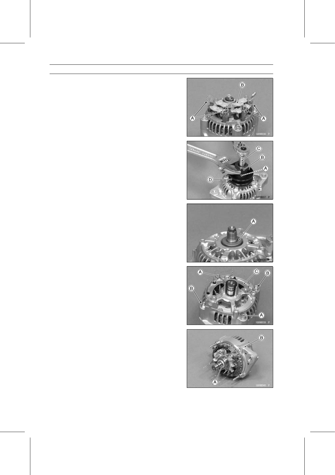
Straighten the stator coil wires [A].

Remove the rectifier [B].

Use the following, loosen the pulley locknut [A].

Socket Wrench [B] (Special Tool: 57001-1236)
Deep Socket Wrench [C]

Special Tool - Socket Wrench, Hex 22: 57001-1236

Remove:

Pulley Locknut
Pulley [D]

Remove the collar [A].

Remove:

Housing Cover Mounting Bolts [A] and Nuts [B]
Housing Cover [C]

Remove:

Rotor [A]
Alternator Housing [B]

ELECTRICAL SYSTEM 17-35

Alternator

Remove:

Bearing Holder [A]
Ball Bearing [B]

To remove the ball bearing [A], use a suitable puller.

Alternator Assembly

Press the bearing and bearing holder onto the rotor shaft.

Straighten the stator coil wires.

Install:

Housing Cover [A]
Housing Cover Mounting Bolts [B] and Nuts [C]

Install the rectifier [A].

Bend the stator coil wire ends [B] around the screw holes.

Tighten the rectifier screws.

Install:

Regulator
Brush Holder
End Cover
Insulator
Terminal Nut

17-36 ELECTRICAL SYSTEM

Alternator

Install:

Collar
Pulley [A]

Use the following, tighten the locknut.

Socket Wrench [B] (Special Tool: 57001-1236)
Deep Socket Wrench [C]

Special Tool - Socket Wrench, Hex 22: 57001-1236

Torque - Alternator Pulley Locknut: 11 N·m (1.1 kgf·m, 97

in·lb)

Alternator Operational Inspection

Check the battery condition.

Conventional Type Battery (see Charging Condition
Inspection (Conventional Type Battery) in the Periodic
Maintenance chapter)
Sealed Type Battery (see Charging Condition Inspection
(Sealed Type Battery))

NOTE

Always check the battery condition before condemning
the alternator. The battery must be fully charged in or-
der to conduct accurate alternator inspection.

Check the wiring (see Wiring Inspection).

Warm up the engine to bring the components up to their
normal operating temperatures.

Stop the engine.

Remove the 30 A main fuse (see Fuse Removal).

Connect the hand tester [A] (range DC 25 V) and ammeter
[B] (range DC 40 A, after the engine start) as shown in the
figure.

Battery [C]
50 A Fuse [D]
Alternator [E]
Load [F]

Measure the alternator output voltage and amperage at 2
000 rpm with the light switch turned OFF.

Alternator Output Voltage

Standard:

13.3

∼ 14.8 V at 25°C (77°F)

Alternator Output Amperage (no load)

Standard:

10 A or less

Stop the engine.

Install the 30 A main fuse (see Fuse Installation).

Measure the alternator output voltage and amperage at 2
000 rpm with the light switch turned ON.

Alternator Output Voltage

Standard:

13.3

∼ 14.8 V at 25°C (77°F)

Alternator Output Amperage (load)

Standard:

20 A or more

If the readings are not within the specified range, check
the alternator.

ELECTRICAL SYSTEM 17-37

Alternator

Stator Coil Inspection

Connect the hand tester (× 1 Ω range) between the coil
wires and read the tester.

Special Tool - Hand Tester: 57001-1394

If the tester does not read as specified, replace the alter-
nator frame.

Stator Coil Resistance: 0.2 Ω or less

Using the highest hand tester range, measure the resis-
tance between the stator coil core and each of the coil
windings.
If there is any reading at all, the stator coil winding has a
short and the alternator housing must be replaced.

Rotor Coil Inspection

Connect the hand tester (× 1 Ω range) between the slip
rings [A] and read the tester.

Special Tool - Hand Tester: 57001-1394

If the tester does not read as specified, replace the rotor
[B].

Rotor Coil Resistance: 2.8

∼ 3.0 Ω

Using the highest tester range, measure the resistance
between the rotor shaft and each of the slip rings.
If there is any reading at all, the rotor coil has a short and
must be replaced.

Slip Ring Cleaning

Visually inspect the slip ring for dirt or pitting.
If necessary, smooth the slip ring with No. 300

∼ No. 500

emery cloth.

Slip Ring Diameter

Measure the diameter of the slip rings.
If the measurement is less than the service limit, replace
the rotor [A].

Slip Ring Diameter

Standard:

14.4 mm (0.57 in.)

Service Limit:

14.0 mm (0.55 in.)

Carbon Brush Length

Measure the length [A] that both carbon brushes that stick
out of the holder.
If either one is worn down to less than the service limit,
replace it.

Carbon Brush Length (Projected Portion)

Standard:

10.5 mm (0.41 in.)

Service Limit:

8.4 mm (0.33 in.)


Content   ..  120  121  122  123   ..